EP0337909A1 - Mower with direct drive - Google Patents
Mower with direct drive Download PDFInfo
- Publication number
- EP0337909A1 EP0337909A1 EP89440022A EP89440022A EP0337909A1 EP 0337909 A1 EP0337909 A1 EP 0337909A1 EP 89440022 A EP89440022 A EP 89440022A EP 89440022 A EP89440022 A EP 89440022A EP 0337909 A1 EP0337909 A1 EP 0337909A1
- Authority
- EP
- European Patent Office
- Prior art keywords
- extends
- mower according
- rotor
- mowing
- mower
- Prior art date
- Legal status (The legal status is an assumption and is not a legal conclusion. Google has not performed a legal analysis and makes no representation as to the accuracy of the status listed.)
- Granted
Links
Images


Classifications
-
- A—HUMAN NECESSITIES
- A01—AGRICULTURE; FORESTRY; ANIMAL HUSBANDRY; HUNTING; TRAPPING; FISHING
- A01D—HARVESTING; MOWING
- A01D34/00—Mowers; Mowing apparatus of harvesters
- A01D34/01—Mowers; Mowing apparatus of harvesters characterised by features relating to the type of cutting apparatus
- A01D34/412—Mowers; Mowing apparatus of harvesters characterised by features relating to the type of cutting apparatus having rotating cutters
- A01D34/63—Mowers; Mowing apparatus of harvesters characterised by features relating to the type of cutting apparatus having rotating cutters having cutters rotating about a vertical axis
- A01D34/64—Mowers; Mowing apparatus of harvesters characterised by features relating to the type of cutting apparatus having rotating cutters having cutters rotating about a vertical axis mounted on a vehicle, e.g. a tractor, or drawn by an animal or a vehicle
- A01D34/66—Mowers; Mowing apparatus of harvesters characterised by features relating to the type of cutting apparatus having rotating cutters having cutters rotating about a vertical axis mounted on a vehicle, e.g. a tractor, or drawn by an animal or a vehicle with two or more cutters
- A01D34/661—Mounting means
Definitions
- the present invention relates to a mower comprising a chassis making it possible to couple said mower to a towing vehicle and a mowing group connected to said chassis by an articulation of an axis directed substantially in the direction of advance, said mowing group being provided with at least one cutting member and at least one rotor arranged near the end of said mowing group where the latter is connected to said chassis, said rotor extending in part at least above part of said or said cutting members and rotating about an axis directed upwards, said mower also comprising drive members of said cutting member (s) and of the rotor comprising in particular a drive shaft in at least one part penetrating into said rotor and rotating substantially around the axis of rotation of the rotor, and a pair of bevel gearwheels arranged at the top of the drive shaft, said mower also comprising an operating member allowing by pivot ement around the axis joint directed substantially in the direction of advance to bring the mowing group in a transport position in which the mowing group is directed upwards.
- a mower In FR-A-2 255 839, such a mower is described, the mowing group of which comprises a cutter bar provided with six discs rotating around axes directed upwards. Discs extending at each end of the cutter bar are surmounted by a rotor.
- This known mower also includes a chassis for coupling it to a tractor vehicle.
- the mowing group is linked to this chassis by means of an axis articulation directed substantially in the direction of advance.
- the chassis is provided with a yoke to which is hingedly linked a support member forming part of the mowing group.
- This support member comprises a foot extending substantially horizontally at the rear end of which is fixed a leg extending substantially vertically.
- the foot is fixed by its front end to the cutter bar and the leg is linked at its upper end to the chassis by the articulation of an axis directed substantially in the direction of advance.
- This support member extends in top view entirely behind the first disc.
- the discs and rotors of this known mower are rotated by a drive shaft passing through the rotor surmounting the first disc.
- This drive shaft has two parts linked together by an elastic coupling. At its lower part, the drive shaft is linked in rotation on the one hand to the first disc and to the rotor surmounting it, and on the other hand to a cylindrical toothed wheel housed in a housing of the cutter bar.
- This cylindrical toothed wheel transmits the movement to a cascade of other cylindrical toothed wheels also housed in the housing of the cutter bar and ensuring driving the other discs and the other rotor in rotation.
- the drive shaft is itself driven in rotation by a shaft whose axis of rotation coincides with the axis of the articulation connecting the mowing group to the chassis and by a couple of conical gear wheels extending at the top of the drive shaft and the binder in rotation to said shaft.
- This shaft is in turn driven in rotation by the PTO of the towing vehicle by means of a cardan shaft and pulley-belt device.
- This known mower also comprises a hydraulic cylinder fixed between the chassis and the mowing group in order to bring the mowing group by pivoting around the articulation in a transport position in which the mowing group extends upwards. .
- This known mower has the particularity of having a mowing group whose overall width at ground level is equal to the cutting width. This is advantageous in several respects. In fact, during the first pass, the mowing group does not fold the product to be harvested without cutting it. Furthermore, during subsequent passages, there is no need to release strips of soil wider than those necessary for the wheels of the towing vehicle extending opposite the cutter bar. As there is no part of the mowing unit which exceeds the cutting width at ground level, the risk of jamming due to clinging of cut product to such a part is eliminated.
- this known mower In transport, this known mower however has the drawback of greatly exceeding the overall width of the towing vehicle. This is due in particular to the fact that the axis of the articulation connecting the mowing group to the chassis extends above the rotor surmounting the first disc, that is to say at a relatively large height relative to the ground . Thus, when the mowing group is pivoted in its transport position in which it extends substantially vertically, the mowing group extends laterally beyond the articulation by a distance equal to the value of said height. This therefore substantially increases the overall width of the tractor-mower assembly and can cause problems when passing through narrow paths or through certain farm entrance gates. This also poses problems of visibility during maneuvers.
- the mower chassis and the coupling device of the towing vehicle are substantially stressed.
- the wheels of the towing vehicle extending on the side opposite to that on which the mowing group extends are substantially unloaded, which can cause stability problems for low-powered towing vehicles.
- the object of the present invention is to solve this problem.
- the mower according to the present The invention is characterized by the fact that the axis of the articulation connecting the mowing group to the chassis extends lower than the center of the pair of bevel gear wheels arranged at the top of the drive shaft penetrating the rotor.
- the center of gravity of the mowing unit extends closer to the median axis of the towing vehicle, which places less stress on the frame of the mower and the coupling device of the towing vehicle and relieves the vehicle wheels less tractor extending on the opposite side to that on which the mowing unit extends.
- the axis of the articulation connecting the mowing group to the chassis is additionally offset towards the towing vehicle. This also makes it possible to bring the mowing unit further towards the towing vehicle when it is pivoted into the transport position.
- the axis of the articulation connecting the mowing group to chassis extends substantially midway between the cutting member above which the rotor at least partially extends and the center of the pair of bevel gear wheels arranged at the top of the drive shaft penetrating said rotor .
- This characteristic is particularly advantageous when the axis of the articulation is additionally offset towards the towing vehicle. In this case, in fact, the joint can extend beyond the cutting width. However, with this characteristic, it is possible in particular to prevent the joint from coming into contact with the swath of cut product formed in the preceding passage, while retaining a reasonable overall width for the tractor vehicle - mower assembly.
- this support member comprises a bearing defining the articulation, a leg extending from this bearing downwards and linked to its foot to a lower carrying member of the mowing group, and an arm s' extending from the bearing upwards and linked at its upper part to a gearbox in which extends the pair of bevel gearwheels arranged at the top of the drive shaft.
- At least the foot of the leg of the support member extends substantially inside the cutting width.
- the drive members additionally comprise a shaft guided in rotation in the bearing of the support member and rotating around the axis of the joint, another pair of bevel gears linked in rotation to said shaft, and an intermediate shaft linked in rotation to this other pair of bevel gears and to the couple of bevel gears arranged at the top of the drive shaft.
- this intermediate shaft extends inside the arm of the support member.
- the mowing unit comprises a cutter bar provided with said cutter or at least part of said cutters, said cutter bar being carried by the support structure composed at least by the support member and the lower carrying member of the mowing group.
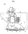
- the mower (1) according to the invention, as shown in Figure 1, comprises a mowing group (2) and a frame (3).
- the mowing unit (2) is linked to the chassis (3) by an articulation (4) with an axis (5) directed in the direction of advance (6) defined in FIGS. 2 and 3.
- the mower (1) is coupled to the coupling device of a towing vehicle (7) so that the mowing group (2) extends, mower (1) seen in the direction of advance ( 6), laterally next to the track of the towing vehicle (7) and transversely to the direction of advance (6).
- the chassis (3) is provided with a coupling device (8) intended to be coupled to the coupling device of the towing vehicle (7).
- the chassis (3) also comprises a support arm (9) linked at one of its ends to the coupling device (8) by means of an articulation (10) with an axis directed in the direction of advance (6).
- the support arm (9) extends transversely to the direction of advance (6) and is connected at its other end to the mowing group (2) by means of the articulation (4).
- the support arm (9) is provided at this other end with a yoke (11).
- this movement limitation member (12) notably limits the pivoting of the support arm (9) down around the articulation (10).
- this movement limitation member (12) is produced in the form of a tie rod provided with an oblong hole.
- the chassis (3) also supports part of the transmission members (13) transmitting the movement from the power take-off (not shown) of the towing vehicle (7) to the drive members (which will be described later) of the mowing unit ( 2).
- these transmission members (13) consist of a universal joint transmission shaft (not shown) which is linked in rotation to a first pulley (14) fixed to the support arm (9) and having an axis of rotation directed in the direction of advance (6), a second pulley (15) whose axis of rotation coincides with the axis (5) of the joint (4), and an endless transmission member ( 16) winding on both pulleys (14, 15).
- the mowing unit (2) comprises a cutter bar (17) provided with cutting members (18, 19, 20).
- the cutting members (18, 19, 20) consist of discs provided at their periphery with cutting tools and rotating around axes directed upwards.
- the mowing group (2) also comprises a supporting structure (21) which supports the cutter bar (17).
- This support structure (21) consists of a support member (22), a lower support member (23), an upper support member (24) and a connecting member (25).
- the lower support member (23) and the upper support member (24) are linked to each other on the one hand via the support member (22) extending at the end of the mowing group ( 2) close to the towing vehicle (7), and secondly by means of the connecting member (25) arranged at the other end of the mowing group (2).
- the support member (22) extends between the two wings (111, 112) (FIG. 2) of the yoke (11) of the support arm (9) and forms with this yoke (11) the articulation (4 ) connecting the mowing unit (2) to the end of the support arm (9) remote from the coupling device (8).
- this articulation (4) is offset towards the towing vehicle (7) and extends next to the cutting member (18) closest to the support member (22) and the rotor (26).
- the axis (5) of the joint (4) extends, mower (1) seen in the direction of advance (6), substantially at the level of the external part of the rear wheel of the towing vehicle (7) extending opposite the mowing group (2).
- the support member (22) additionally contains part of the drive members intended in particular for driving the cutting members (18, 19, 20). These drive members will be described later in more detail. In FIG. 1, it can simply be seen that a portion of these extend through the cutting member (18) extending closest to the towing vehicle (7). It is partly for this purpose that this cutting member (18) is surmounted by a rotor (26) which also rotates around an axis directed upwards. In the example shown, the rotor (26) rotates at the same speed and around the same axis as the cutting member (18) which it surmounts.
- the mower (1) of the present invention is thus what is called a direct drive mower.
- the cutting width of the mowing group (2) is substantially equal to the overall width of said mowing group (2) measured at ground level.
- the connecting member (25) for its part, also fulfills in the example shown a function of separation between the product cut by the cutting member (20) which extends closest to it and the product still standing. .
- an operating member (27) and a load shedding member (28) of the mowing group (2) are arranged between the coupling device (8) and the mowing group (2).
- the operating member (27) is a hydraulic cylinder and the load shedding member (28), a tension spring.
- the operating member (27) and the load-shedding member (28) are linked to the coupling device (8) by means of the same axis (29) as that which links the movement limitation member (12) to said coupling device (8).
- This movement limitation member (12) is also linked to the support arm (9) by an axis (30).
- the operating member (27) is linked to the mowing group (2) by means of a lever (31) which is linked to the mowing group (2) by an axis (32) and to the operating member (27) by an axis (33).
- the load-shedding member (28) is linked to the mowing group (2) by an axis (34).
- the axes (29, 30, 32, 33 and 34) are directed in the direction of advance (6).
- the mowing unit (2) comprises a protection device (35) (shown in phantom) which surrounds the cutting members (18, 19, 20).
- the chassis (3) is provided with a protective cover (36) (also shown in dashed lines) which partially surrounds the pulleys (14, 15) and the endless transmission member (16).
- the support member (22) forms with the yoke (11) of the support arm (9) the joint (4).
- the support member (22) comprises two cylindrical surfaces (37) capable of rotating in the wings (111, 112) of the yoke (11). These cylindrical bearing surfaces (37) are produced in the form of flanges which are mounted on a housing (38) which also includes the support member (22).
- the support member (22) finally further comprises a leg (39) which extends from the housing (38) downwards towards the lower support member (23).
- This leg (39) comprises a foot (40) by means of which the support member (22) is linked to the lower support member (23).
- the housing (38) extends substantially symmetrically with respect to the longitudinal plane (41) (FIG.
- the leg (39) extends from the housing (38) backwards and downwards.
- the housing (38) extends in plan view for the most part outside the cutting zone (42) of the cutting members (18, 19, 20) while the foot (40) of the leg (39) extends inside this cutting zone (42).
- the leg (39) also extends in part from the housing (38) towards the middle part of the mowing unit (2).
- the foot (40) extends behind the cutting member (18) situated next to the support member (22) and that a large part of the leg ( 39) extends above said cutting member (18) and next to the rotor (26) surmounting this cutting member (18).
- the support member (22) also includes an arm (43) which extends from the housing (38) upwards and towards the middle part of the mowing group (2). This arm (43) has a bore (44) into which the axis (32) is introduced by means of which the lever (31) is linked to the mowing group (2).
- this axis (32) also serves to link the upper support member (24) to the support member (22).
- This upper support member (24) consists of a tube extending substantially in the longitudinal plane (41) of the mowing unit (2) and over a large part of its length parallel to the cutter bar (17) and to a certain distance above it. At its end close to the support member (22) on the other hand, it extends substantially parallel to the arm (43).
- the upper support member (24) comprises two wings (45) forming a yoke inside which the arm (43) extends and which is linked to this arm (43) by means of the axis (32).
- the upper support member (24) is also provided with a connection plate (46) by means of which it is screwed to the housing (38) of the support member (22).
- the carrier organ upper (24) is thus detachably connected to the support member (22).
- connection plate (46) is asymmetrical and has a stop (47) extending in the pivoting region of the lever (31).
- the lever (31) In the working position, the lever (31) is moved away from the stop (47), which allows the mowing group (2) to adapt to the ground surface by pivoting by a certain amount around the joint. (4).
- the operating member (27) When the operating member (27) is actuated to pivot the mowing group (2) upwards in order to bring it into a transport position (FIG. 5), the pivoting of the mowing group (2) will not start until the lever (31) has come into contact with the stop (47).
- the support member (22) is linked via the foot (40) of the leg (39) to the lower support member (23).
- the foot (40) of the leg (39) of the support member (22) comprises a flange (48) by means of which the support member (22) is screwed to a carrier plate. (49) of the lower support member (23).
- This carrier plate (49) is fixed to a stiffener (50) which extends behind the cutter bar (17) which comprises a casing (51) above which the cutters (18, 19, 20 extend) ).
- the stiffener (50) consists of a tube extending parallel to said casing (51).
- the lower support member (23) and the upper support member (24) are so linked removable from the connecting member (25).
- the support structure (21) thus formed carries the cutter bar (17), the housing (51) of which is screwed to the lower support member (23) which extends below the cutting plane of the cutting members ( 18, 19, 20).
- These drive members comprise a shaft (52) guided in rotation in the cylindrical surfaces (37) of the housing (38) of the support member (22).
- the axis of rotation of this shaft (52) is thus coincident with the axis (5) of the joint (4).
- the guiding in rotation of this shaft (52) in the bearing (53) formed by the cylindrical bearings (37) and the housing (38) is within the reach of those skilled in the art.
- the pulley (15) is linked in rotation to the rear end of the shaft (52) which exits for this purpose from the bearing (53).
- the shaft (52) is linked in rotation to a bevel gear (54) which meshes with a bevel gear (55).
- the latter bevel gear (55) is linked in rotation to one end of an intermediate shaft (56) which is guided in rotation in the arm (43) by means of bearings (57).
- the intermediate shaft (56) enters a gearbox (58) extending above the cutting member (18) and the rotor (26).
- this gearbox (58) and the arm (43) are formed in one piece.
- the arm (43) has a flange (59) which allows the screwing of the gearbox assembly (58) - arm (43) on the housing (38). So that the bevel gear (55) which is guided in rotation in the arm (43), is correctly positioned with respect to the bevel gear (54) guided in rotation in the housing (38), a centering ring (60 ) centers the arm (43) relative to the housing (38).
- the intermediate shaft (56) is linked in rotation to a bevel gear (61) which meshes with a bevel gear (62).
- This last bevel gear (62) is linked in rotation to a drive shaft (63) whose axis of rotation (64) coincides with the axis of rotation of the cutting member (18) and the rotor (26) surmounting this cutting member (18).
- the drive shaft (63) is composed of three parts: an upper part (65), an intermediate part (66) and a lower part (67). These three parts (65, 66, 67) of the drive shaft (63) are linked together by two elastic couplings (68, 69).
- the upper part (65) of the drive shaft (63), at the upper end of which the conical toothed wheel (62) is linked in rotation, is guided in rotation in the gearbox (58) by means two bearings 70.
- the upper part (65) of the drive shaft (63) is linked in rotation to a drive flange (71) which is itself fixed to the elastic coupling (68) .
- the intermediate part (66) of the drive shaft (63) is linked in rotation at its upper end to a first driver (72) and at its lower end to a second driver (73).
- the first driver (72) is attached to the coupling (68), while the second driver (73) is attached to the coupling (69).
- the lower part (67) of the drive shaft (63) is guided in rotation in a bearing (74) by means of bearings (75), said bearing (74) being fixed to the upper part of the casing ( 51).
- the lower part (67) of the drive shaft (63) is linked in rotation to a hub (76) integral with the cutting member (18) and a part of the rotor (26) .
- This hub (76) is also fixed to the elastic coupling (69).
- the lower part (67) of the drive shaft (63) is linked in rotation to additional drive members known to those skilled in the art and extending inside the casing (51), such as cylindrical gears, for example meshing with one another, for the purpose of driving the other cutting members (19, 20).
- the rotor (26) consists of two half-rotors (77, 78).
- the upper half-rotor (77) is fixed to the flange (71), while the lower half-rotor (78) is fixed to the cutting member (18).
- the lower half-rotor (78) is provided with a cylindrical wall (79) which extends somewhat inside the lower part of the upper half-rotor (77) and which has a diameter outside slightly smaller than the inside diameter of the lower part of the upper half-rotor (77).
- the lower half-rotor (78) is also provided with an annular part (80) which is connected to the lower part of the cylindrical wall (79) and which has an outside diameter greater than the outside diameter of the rest of the lower half-rotor (78) and the upper half-rotor (77).
- the upper half-rotor (77) also has at its upper part an annular wall (81) having an outside diameter substantially equal to the outside diameter of the annular wall (80).
- the axis (5) of the articulation (4) extends at a distance (84) from the axis of rotation (64) of the cutting member (18) in the direction of the towing vehicle (7) and at a distance (85) lower than the center (83) of the pair of bevel gear wheels (61, 62) arranged in the gearbox (58).
- the axis (5) extends substantially midway between the cutting member (18) and the center (83) of the pair of bevel gearwheels (61, 62), and approximately at same level as the annular wall (81) of the rotor (26).
- the mower (1) which has just been described operates as follows:
- Its coupling device (8) is coupled to the coupling device of the towing vehicle (7) and the cardan drive shaft (not shown) which is rotatably connected at one of its ends to the pulley (14 ), is coupled to the PTO (not shown) of the towing vehicle (7).
- the towing vehicle (7) moves the mower (1) in the feed direction (6) and its power take-off rotates the cutting members (18, 19, 20) and the rotor (26) surmounting the cutting member (18), via the transmission members (13) and the various drive members which have been described.
- the cutting members (18, 19, 20) cut the product to be harvested which is located in the cutting zone (42).
- the drive shaft (63) largely extends inside the rotor (26), any risk of catching cut product on the drive shaft (63) is eliminated.
- the support arm (9) can pivot by a certain amount with respect to the coupling device (8) and since the mowing unit (2) can pivot by a certain value with respect to the support arm ( 9), said mowing group (2) can adapt well to the configuration of the ground to be mowed.
- the load-shedding member (28) reduces the force with which the mowing unit (2) rests on the ground, both at the cutting member (18) and at the cutting member. (20). This in fact results from the fact that the attachment point - that is to say the axis (34) - of the load shedding member (28) is located on the mowing group (2) so as to create a return torque directed anti-clockwise when looking at the mower (1) from the rear in the forward direction (6).
- the coupling device of the towing vehicle (7) is first actuated, which has the effect of lifting the mower (1) as soon as the travel limitation member (12) stops the pivoting of the support arm (9) down around the axis (10).
- the actuating member (27) is then actuated, which causes the mowing group (2) to pivot upwards around the articulation (4).
- the transport position is reached when the mowing unit (2) substantially occupies a vertical position.
- the mowing group (2) does not extends only a relatively moderate distance (87) beyond the rear wheel of the towing vehicle (7) situated on the same side as the mowing unit (2), even though the mower (1) is a mower direct drive. This has many advantages as described above.
Abstract
Description
La présente invention concerne une faucheuse comportant un châssis permettant d'atteler ladite faucheuse à un véhicule tracteur et un groupe de fauche lié audit châssis par une articulation d'axe dirigé sensiblement suivant la direction d'avance, ledit groupe de fauche étant muni d'au moins un organe de coupe et d'au moins un rotor agencé près de l'extrémité dudit groupe de fauche où celui-ci est lié audit châssis, ledit rotor s'étendant en partie au moins au-dessus d'une partie dudit ou desdits organes de coupe et tournant autour d'un axe dirigé vers le haut, ladite faucheuse comportant également des organes d'entraînement du ou desdits organes de coupe et du rotor comprenant notamment un arbre d'entraînement en au moins une partie pénétrant dans ledit rotor et tournant sensiblement autour de l'axe de rotation du rotor, et un couple de roues dentées coniques agencé au sommet de l'arbre d'entraînement, ladite faucheuse comportant par ailleurs un organe de manoeuvre permettant par pivotement autour de l'articulation d'axe dirigé sensiblement dans la direction d'avance d'amener le groupe de fauche dans une position de transport dans laquelle le groupe de fauche est dirigé vers le haut.The present invention relates to a mower comprising a chassis making it possible to couple said mower to a towing vehicle and a mowing group connected to said chassis by an articulation of an axis directed substantially in the direction of advance, said mowing group being provided with at least one cutting member and at least one rotor arranged near the end of said mowing group where the latter is connected to said chassis, said rotor extending in part at least above part of said or said cutting members and rotating about an axis directed upwards, said mower also comprising drive members of said cutting member (s) and of the rotor comprising in particular a drive shaft in at least one part penetrating into said rotor and rotating substantially around the axis of rotation of the rotor, and a pair of bevel gearwheels arranged at the top of the drive shaft, said mower also comprising an operating member allowing by pivot ement around the axis joint directed substantially in the direction of advance to bring the mowing group in a transport position in which the mowing group is directed upwards.
Dans la FR-A-2 255 839 est décrite une telle faucheuse dont le groupe de fauche comporte une barre de coupe munie de six disques tournant autour d'axes dirigés vers le haut. Les disques s'étendant à chaque extrémité de la barre de coupe sont surmontés par un rotor. Cette faucheuse connue comporte par ailleurs un châssis permettant de l'atteler à un véhicule tracteur. Le groupe de fauche est lié à ce châssis au moyen d'une articulation d'axe dirigé sensiblement suivant la direction d'avance. A cet effet, le châssis est muni d'une chape à laquelle est lié de manière articulée un organe-support faisant partie du groupe de fauche. Cet organe-support comporte un pied s'étendant sensiblement horizontalement à l'extrémité arrière duquel est fixée une jambe s'étendant sensiblement verticalement. Le pied est fixé par son extrémité avant à la barre de coupe et la jambe est liée à son extrémité supérieure au châssis par l'articulation d'axe dirigé sensiblement suivant la direction d'avance. Cet organe-support s'étend en vue de dessus entièrement derrière le premier disque. Les disques et les rotors de cette faucheuse connue sont entraînés en rotation par un arbre d'entraînement traversant le rotor surmontant le premier disque. Cet arbre d'entraînement comporte deux parties liées entre elles par un accouplement élastique. A sa partie inférieure, l'arbre d'entraînement est lié en rotation d'une part au premier disque et au rotor surmontant celui-ci, et d'autre part à une roue dentée cylindrique logée dans un carter de la barre de coupe. Cette roue dentée cylindrique transmet le mouvement à une cascade d'autres roues dentées cylindriques également logées dans le carter de la barre de coupe et assurant l'entraînement en rotation des autres disques et de l'autre rotor. L'arbre d'entraînement est lui-même entraîné en rotation par un arbre dont l'axe de rotation est confondu avec l'axe de l'articulation liant le groupe de fauche au châssis et par un couple de roues dentées coniques s'étendant au sommet de l'arbre d'entraînement et le liant en rotation audit arbre. Cet arbre est quant à lui entraîné en rotation par la prise de force du véhicule tracteur par l'intermédiaire d'un dispositif à arbre à cardans et à poulies-courroies. Cette faucheuse connue comporte aussi un vérin hydraulique fixé entre le châssis et le groupe de fauche en vue d'amener le groupe de fauche par pivotement autour de l'articulation dans une position de transport dans laquelle le groupe de fauche s'étend vers le haut.In FR-A-2 255 839, such a mower is described, the mowing group of which comprises a cutter bar provided with six discs rotating around axes directed upwards. Discs extending at each end of the cutter bar are surmounted by a rotor. This known mower also includes a chassis for coupling it to a tractor vehicle. The mowing group is linked to this chassis by means of an axis articulation directed substantially in the direction of advance. For this purpose, the chassis is provided with a yoke to which is hingedly linked a support member forming part of the mowing group. This support member comprises a foot extending substantially horizontally at the rear end of which is fixed a leg extending substantially vertically. The foot is fixed by its front end to the cutter bar and the leg is linked at its upper end to the chassis by the articulation of an axis directed substantially in the direction of advance. This support member extends in top view entirely behind the first disc. The discs and rotors of this known mower are rotated by a drive shaft passing through the rotor surmounting the first disc. This drive shaft has two parts linked together by an elastic coupling. At its lower part, the drive shaft is linked in rotation on the one hand to the first disc and to the rotor surmounting it, and on the other hand to a cylindrical toothed wheel housed in a housing of the cutter bar. This cylindrical toothed wheel transmits the movement to a cascade of other cylindrical toothed wheels also housed in the housing of the cutter bar and ensuring driving the other discs and the other rotor in rotation. The drive shaft is itself driven in rotation by a shaft whose axis of rotation coincides with the axis of the articulation connecting the mowing group to the chassis and by a couple of conical gear wheels extending at the top of the drive shaft and the binder in rotation to said shaft. This shaft is in turn driven in rotation by the PTO of the towing vehicle by means of a cardan shaft and pulley-belt device. This known mower also comprises a hydraulic cylinder fixed between the chassis and the mowing group in order to bring the mowing group by pivoting around the articulation in a transport position in which the mowing group extends upwards. .
Cette faucheuse connue présente la particularité d'avoir un groupe de fauche dont la largeur hors-tout au niveau du sol est égale à la largeur de coupe. Ceci est avantageux à plusieurs égards. En effet, lors du premier passage le groupe de fauche ne plie pas de produit à récolter sans le couper. Par ailleurs, lors des passages ultérieurs il n'y a pas lieu de dégager de bandes de sol plus larges que celles nécessaires aux roues du véhicule tracteur s'étendant en regard de la barre de coupe. Comme il n'y a pas de partie du groupe de fauche qui dépasse au niveau du sol la largeur de coupe, on élimine les risques de bourrage dus à des accrochages de produit coupé à une telle partie.This known mower has the particularity of having a mowing group whose overall width at ground level is equal to the cutting width. This is advantageous in several respects. In fact, during the first pass, the mowing group does not fold the product to be harvested without cutting it. Furthermore, during subsequent passages, there is no need to release strips of soil wider than those necessary for the wheels of the towing vehicle extending opposite the cutter bar. As there is no part of the mowing unit which exceeds the cutting width at ground level, the risk of jamming due to clinging of cut product to such a part is eliminated.
Au transport, cette faucheuse connue présente cependant l'inconvénient de dépasser largement la largeur hors-tout du véhicule tracteur. Ceci est dû notamment au fait que l'axe de l'articulation liant le groupe de fauche au châssis s'étend au-dessus du rotor surmontant le premier disque, c'est-à-dire à une hauteur relativement importante par rapport au sol. Ainsi, lorsque le groupe de fauche est pivoté dans sa position de transport dans laquelle il s'étend sensiblement verticalement, le groupe de fauche s'étend latéralement au-delà de l'articulation d'une distance égale à la valeur de ladite hauteur. Ceci augmente donc substantiellement la largeur hors-tout de l'ensemble véhicule tracteur - faucheuse et peut poser des problèmes pour passer dans des chemins étroits ou par certains portails d'entrée de fermes. Ceci pose aussi des problèmes de visibilité lors de manoeuvres. Comme le centre de gravité du groupe de fauche est relativement déporté latéralement, le châssis de la faucheuse et le dispositif d'attelage du véhicule tracteur sont substantiellement sollicités. En sus, les roues du véhicule tracteur s'étendant du côté opposé à celui où s'étend le groupe de fauche, sont substantiellement déchargées, ce qui peut poser des problèmes de stabilité pour des véhicules tracteurs de faible puissance. Le but de la présente invention est de solutionner ce problème.In transport, this known mower however has the drawback of greatly exceeding the overall width of the towing vehicle. This is due in particular to the fact that the axis of the articulation connecting the mowing group to the chassis extends above the rotor surmounting the first disc, that is to say at a relatively large height relative to the ground . Thus, when the mowing group is pivoted in its transport position in which it extends substantially vertically, the mowing group extends laterally beyond the articulation by a distance equal to the value of said height. This therefore substantially increases the overall width of the tractor-mower assembly and can cause problems when passing through narrow paths or through certain farm entrance gates. This also poses problems of visibility during maneuvers. As the center of gravity of the mower unit is relatively laterally offset, the mower chassis and the coupling device of the towing vehicle are substantially stressed. In addition, the wheels of the towing vehicle extending on the side opposite to that on which the mowing group extends, are substantially unloaded, which can cause stability problems for low-powered towing vehicles. The object of the present invention is to solve this problem.
A cet effet, la faucheuse selon la présente invention est caractérisée par le fait que l'axe de l'articulation liant le groupe de fauche au châssis s'étend plus bas que le centre du couple de roues dentées coniques agencé au sommet de l'arbre d'entraînement pénétrant dans le rotor.To this end, the mower according to the present The invention is characterized by the fact that the axis of the articulation connecting the mowing group to the chassis extends lower than the center of the pair of bevel gear wheels arranged at the top of the drive shaft penetrating the rotor.
Avec cet agencement, la hauteur à laquelle s'étend l'axe de l'articulation liant le groupe de fauche au châssis, est plus faible. En conséquence, lorsque le groupe de fauche est pivoté dans sa position de transport, celui-ci s'étend latéralement au-delà de l'axe de l'articulation d'une distance plus faible, tandis que sa partie qui s'étendait au travail plus haut que l'axe de l'articulation, est passée de l'autre côté dudit axe vers le véhicule tracteur. De ce fait, la largeur hors-tout de l'ensemble véhicule tracteur - faucheuse est plus réduit. Par ailleurs, le centre de gravité du groupe de fauche s'étend plus près de l'axe médian du véhicule tracteur, ce qui sollicite moins le châssis de la faucheuse et le dispositif d'attelage du véhicule tracteur et déleste moins les roues du véhicule tracteur s'étendant du côté opposé à celui où s'étend le groupe de fauche.With this arrangement, the height at which the axis of the articulation connecting the mowing group to the chassis extends, is lower. Consequently, when the mower unit is pivoted in its transport position, this latter extends laterally beyond the axis of the articulation by a smaller distance, while its part which extended to the work higher than the axis of the joint, is passed on the other side of said axis towards the towing vehicle. As a result, the overall width of the tractor-mower assembly is reduced. In addition, the center of gravity of the mowing unit extends closer to the median axis of the towing vehicle, which places less stress on the frame of the mower and the coupling device of the towing vehicle and relieves the vehicle wheels less tractor extending on the opposite side to that on which the mowing unit extends.
Préférentiellement, l'axe de l'articulation liant le groupe de fauche au châssis est en sus déporté vers le véhicule tracteur. Ceci permet encore de ramener d'avantage le groupe de fauche vers le véhicule tracteur lors de son pivotement dans la position de transport.Preferably, the axis of the articulation connecting the mowing group to the chassis is additionally offset towards the towing vehicle. This also makes it possible to bring the mowing unit further towards the towing vehicle when it is pivoted into the transport position.
Avantageusement, il est prévu dans l'invention que l'axe de l'articulation liant le groupe de fauche au châssis s'étend sensiblement à mi-distance entre l'organe de coupe au-dessus duquel s'étend au moins partiellement le rotor et le centre du couple de roues dentées coniques agencé au sommet de l'arbre d'entraînement pénétrant dans ledit rotor. Cette caractéristique est particulièrement intéressante lorsque l'axe de l'articulation est en sus déporté vers le véhicule tracteur. Dans ce cas en effet, l'articulation peut s'étendre au-delà de la largeur de coupe. Or, avec cette caractéristique, on peut notamment éviter que l'articulation ne vienne en contact avec l'andain de produit coupé formé au passage précédent, tout en conservant une largeur hors-tout raisonnable à l'ensemble véhicule tracteur - faucheuse.Advantageously, it is provided in the invention that the axis of the articulation connecting the mowing group to chassis extends substantially midway between the cutting member above which the rotor at least partially extends and the center of the pair of bevel gear wheels arranged at the top of the drive shaft penetrating said rotor . This characteristic is particularly advantageous when the axis of the articulation is additionally offset towards the towing vehicle. In this case, in fact, the joint can extend beyond the cutting width. However, with this characteristic, it is possible in particular to prevent the joint from coming into contact with the swath of cut product formed in the preceding passage, while retaining a reasonable overall width for the tractor vehicle - mower assembly.
La réalisation de l'axe d'articulation est particulièrement aisée lorsqu'à l'extrémité du groupe de fauche où celui-ci est lié au châssis, ledit groupe de fauche est muni d'un organe-support par l'intermédiaire duquel le groupe de fauche est lié au châssis. Dans l'invention, cet organe-support comporte un palier définissant l'articulation, une jambe s'étendant à partir de ce palier vers le bas et liée à son pied à un organe porteur inférieur du groupe de fauche, et un bras s'étendant à partir du palier vers le haut et lié à sa partie supérieure à un carter de renvoi dans lequel s'étend le couple de roues dentées coniques agencé au sommet de l'arbre d'entraînement.The realization of the articulation axis is particularly easy when at the end of the mowing group where the latter is linked to the chassis, said mowing group is provided with a support member by means of which the group mower is linked to the chassis. In the invention, this support member comprises a bearing defining the articulation, a leg extending from this bearing downwards and linked to its foot to a lower carrying member of the mowing group, and an arm s' extending from the bearing upwards and linked at its upper part to a gearbox in which extends the pair of bevel gearwheels arranged at the top of the drive shaft.
Avantageusement, au moins le pied de la jambe de l'organe-support s'étend sensiblement à l'intérieur de la largeur de coupe.Advantageously, at least the foot of the leg of the support member extends substantially inside the cutting width.
Selon une caractéristique supplémentaire, il est également prévu dans l'invention que les organes d'entraînement comportent en sus un arbre guidé en rotation dans le palier de l'organe-support et tournant autour de l'axe de l'articulation, un autre couple de roues dentées coniques lié en rotation audit arbre, et un arbre intermédiaire lié en rotation à cet autre couple de roues dentées coniques et au couple de roues dentées coniques agencé au sommet de l'arbre d'entraînement.According to an additional characteristic, it is also provided in the invention that the drive members additionally comprise a shaft guided in rotation in the bearing of the support member and rotating around the axis of the joint, another pair of bevel gears linked in rotation to said shaft, and an intermediate shaft linked in rotation to this other pair of bevel gears and to the couple of bevel gears arranged at the top of the drive shaft.
Avantageusement, cet arbre intermédiaire s'étend à l'intérieur du bras de l'organe-support.Advantageously, this intermediate shaft extends inside the arm of the support member.
Selon une autre caractéristique, il est également prévu dans l'invention que le groupe de fauche comporte une barre de coupe munie dudit organe de coupe ou d'une partie au moins desdits organes de coupe, ladite barre de coupe étant portée par la structure porteuse composée au moins par l'organe-support et l'organe porteur inférieur du groupe de fauche.According to another characteristic, it is also provided in the invention that the mowing unit comprises a cutter bar provided with said cutter or at least part of said cutters, said cutter bar being carried by the support structure composed at least by the support member and the lower carrying member of the mowing group.
D'autres caractéristiques de l'invention sont contenues dans les autres sous-revendications et ressortent clairement de la description ci-dessous d'un exemple préféré (mais non-limitatif) de réalisation de l'invention faite en référence au dessin annexé sur lequel :
- - la figure 1 représente, en position de travail, une faucheuse selon l'invention vue de l'arrière dans le sens d'avance et attelée à un véhicule- tracteur,
- - la figure 2 représente à une échelle agrandie une vue de dessus de la liaison du groupe de fauche au châssis,
- - la figure 3 représente à une échelle agrandie une vue latérale du groupe de fauche seul,
- - la figure 4 réprésente à une échelle agrandie une vue en coupe suivant le plan IV-IV défini sur la figure 2, et
- - la figure 5 représente la faucheuse pivotée en position de transport.
- - Figure 1 shows, in the working position, a mower according to the invention seen from the rear in the direction of advance and coupled to a vehicle- tractor,
- FIG. 2 represents on an enlarged scale a top view of the connection of the mowing unit to the chassis,
- FIG. 3 represents on a larger scale a side view of the mowing group alone,
- FIG. 4 represents on an enlarged scale a sectional view along the plane IV-IV defined in FIG. 2, and
- - Figure 5 shows the mower pivoted in the transport position.
La faucheuse (1) selon l'invention, telle qu'elle est représentée sur la figure 1, comporte un groupe de fauche (2) et un châssis (3). Le groupe de fauche (2) est lié au châssis (3) par une articulation (4) d'axe (5) dirigé suivant la direction d'avance (6) définie sur les figures 2 et 3.The mower (1) according to the invention, as shown in Figure 1, comprises a mowing group (2) and a frame (3). The mowing unit (2) is linked to the chassis (3) by an articulation (4) with an axis (5) directed in the direction of advance (6) defined in FIGS. 2 and 3.
Au travail, la faucheuse (1) est attelée au dispositif d'attelage d'un véhicule tracteur (7) de telle sorte que le groupe de fauche (2) s'étende, faucheuse (1) vue dans la direction d'avance (6), latéralement à côté de la voie du véhicule tracteur (7) et transversalement à la direction d'avance (6). A cet effet, le châssis (3) est muni d'un dispositif d'attelage (8) destiné à être accouplé au dispositif d'attelage du véhicule tracteur (7). Le châssis (3) comporte par ailleurs un bras-support (9) lié à l'une de ses extrémités au dispositif d'attelage (8) au moyen d'une articulation (10) d'axe dirigé suivant la direction d'avance (6). Le bras-support (9) s'étend transversalement à la direction d'avance (6) et est lié à son autre extrémité au groupe de fauche (2) au moyen de l'articulation (4). A cet effet, le bras-support (9) est muni à cette autre extrémité d'une chape (11).At work, the mower (1) is coupled to the coupling device of a towing vehicle (7) so that the mowing group (2) extends, mower (1) seen in the direction of advance ( 6), laterally next to the track of the towing vehicle (7) and transversely to the direction of advance (6). To this end, the chassis (3) is provided with a coupling device (8) intended to be coupled to the coupling device of the towing vehicle (7). The chassis (3) also comprises a support arm (9) linked at one of its ends to the coupling device (8) by means of an articulation (10) with an axis directed in the direction of advance (6). The support arm (9) extends transversely to the direction of advance (6) and is connected at its other end to the mowing group (2) by means of the articulation (4). To this end, the support arm (9) is provided at this other end with a yoke (11).
Entre le dispositif d'attelage (8) et le bras-support (9) s'étend également un organe de limitation de débattement (12) limitant le débattement possible du bras- support (9) par rapport au dispositif d'attelage (8). Cet organe de limitation de débattement (12) limite notamment le pivotement du bras-support (9) vers le bas autour de l'articulation (10). Dans l'exemple représenté, cet organe de limitation de débattement (12) est réalisé sous forme de tirant muni d'un trou oblong.Between the coupling device (8) and the support arm (9) also extends a movement limiting member (12) limiting the possible movement of the support arm (9) relative to the coupling device (8 ). This movement limitation member (12) notably limits the pivoting of the support arm (9) down around the articulation (10). In the example shown, this movement limitation member (12) is produced in the form of a tie rod provided with an oblong hole.
Le châssis (3) supporte également une partie des organes de transmission (13) transmettant le mouvement depuis la prise de force (non représentée) du véhicule tracteur (7) aux organes d'entraînement (qui seront décrits ultérieurement) du groupe de fauche (2). Dans l'exemple représenté, ces organes de transmission (13) sont constitués par un arbre de transmission à cardans (non représenté) qui est lié en rotation à une première poulie (14) fixée au bras-support (9) et ayant un axe de rotation dirigé suivant la direction d'avance (6), une seconde poulie (15) dont l'axe de rotation est confondu avec l'axe (5) de l'articulation (4), et un organe de transmission sans fin (16) s'enroulant sur les deux poulies (14, 15).The chassis (3) also supports part of the transmission members (13) transmitting the movement from the power take-off (not shown) of the towing vehicle (7) to the drive members (which will be described later) of the mowing unit ( 2). In the example shown, these transmission members (13) consist of a universal joint transmission shaft (not shown) which is linked in rotation to a first pulley (14) fixed to the support arm (9) and having an axis of rotation directed in the direction of advance (6), a second pulley (15) whose axis of rotation coincides with the axis (5) of the joint (4), and an endless transmission member ( 16) winding on both pulleys (14, 15).
Le groupe de fauche (2) comporte une barre de coupe (17) munie d'organes de coupe (18, 19, 20). Dans l'exemple représenté, les organes de coupe (18, 19, 20) sont constitués par des disques munis à leur périphérie d'outils de coupe et tournant autour d'axes dirigés vers le haut. Le groupe de fauche (2) comporte par ailleurs une structure porteuse (21) qui supporte la barre de coupe (17). Cette structure porteuse (21) se compose d'un organe-support (22), d'un organe porteur inférieur (23), d'un organe porteur supérieur (24) et d'un organe de liaison (25). L'organe porteur inférieur (23) et l'organe porteur supérieur (24) sont liés entre eux d'une part par l'intermédiaire de l'organe-support (22) s'étendant à l'extrémité du groupe de fauche (2) proche du véhicule tracteur (7), et d'autre part par l'intermédiaire de l'organe de liaison (25) aménagé à l'autre extrémité du groupe de fauche (2). L'organe-support (22) s'étend entre les deux ailes (111, 112) (figure 2) de la chape (11) du bras-support (9) et forme avec cette chape (11) l'articulation (4) liant le groupe de fauche (2) à l'extrémité du bras-support (9) éloignée du dispositif d'attelage (8).The mowing unit (2) comprises a cutter bar (17) provided with cutting members (18, 19, 20). In the example shown, the cutting members (18, 19, 20) consist of discs provided at their periphery with cutting tools and rotating around axes directed upwards. The mowing group (2) also comprises a supporting structure (21) which supports the cutter bar (17). This support structure (21) consists of a support member (22), a lower support member (23), an upper support member (24) and a connecting member (25). The lower support member (23) and the upper support member (24) are linked to each other on the one hand via the support member (22) extending at the end of the mowing group ( 2) close to the towing vehicle (7), and secondly by means of the connecting member (25) arranged at the other end of the mowing group (2). The support member (22) extends between the two wings (111, 112) (FIG. 2) of the yoke (11) of the support arm (9) and forms with this yoke (11) the articulation (4 ) connecting the mowing unit (2) to the end of the support arm (9) remote from the coupling device (8).
Comme visible sur la figure 1, cette articulation (4) est déportée vers le véhicule tracteur (7) et s'étend à côté de l'organe de coupe (18) le plus près de l'organe-support (22) et du rotor (26). On voit en sus sur la figure 1, que l'axe (5) de l'articulation (4) s'étend, faucheuse (1) vue dans la direction d'avance (6), sensiblement au niveau de la partie extérieure de la roue arrière du véhicule-tracteur (7) s'étendant en regard du groupe de fauche (2).As visible in FIG. 1, this articulation (4) is offset towards the towing vehicle (7) and extends next to the cutting member (18) closest to the support member (22) and the rotor (26). We see in addition in Figure 1, that the axis (5) of the joint (4) extends, mower (1) seen in the direction of advance (6), substantially at the level of the external part of the rear wheel of the towing vehicle (7) extending opposite the mowing group (2).
L'organe-support (22) contient en sus une partie des organes d'entraînement destinés notamment à l'entraînement des organes de coupe (18, 19, 20). Ces organes d'entraînement seront décrits ultérieurement plus en détail. Sur la figure l, on voit simplement qu'une partie de ceux-ci s'étendent à travers l'organe de coupe (18) s'étendant le plus près du véhicule tracteur (7). C'est en partie à cet effet, que cet organe de coupe (18) est surmonté par un rotor (26) qui tourne également autour d'un axe dirigé vers le haut. Dans l'exemple représenté, le rotor (26) tourne à la même vitesse et autour du même axe que l'organe de coupe (18) qu'il surmonte.The support member (22) additionally contains part of the drive members intended in particular for driving the cutting members (18, 19, 20). These drive members will be described later in more detail. In FIG. 1, it can simply be seen that a portion of these extend through the cutting member (18) extending closest to the towing vehicle (7). It is partly for this purpose that this cutting member (18) is surmounted by a rotor (26) which also rotates around an axis directed upwards. In the example shown, the rotor (26) rotates at the same speed and around the same axis as the cutting member (18) which it surmounts.
La faucheuse (1) de la présente invention est ainsi ce que l'on appelle une faucheuse à entraînement direct. Dans une telle faucheuse, la largeur de coupe du groupe de fauche (2) est sensiblement égale à la largeur hors-tout dudit groupe de fauche (2) mesurée au niveau du sol.The mower (1) of the present invention is thus what is called a direct drive mower. In such a mower, the cutting width of the mowing group (2) is substantially equal to the overall width of said mowing group (2) measured at ground level.
L'organe de liaison (25) quant à lui remplit dans l'exemple représenté également une fonction de séparation entre le produit coupé par l'organe de coupe (20) qui s'étend le plus près de lui et le produit encore sur pied.The connecting member (25), for its part, also fulfills in the example shown a function of separation between the product cut by the cutting member (20) which extends closest to it and the product still standing. .
Entre le dispositif d'attelage (8) et le groupe de fauche (2) sont aménagés un organe de manoeuvre (27) et un organe de délestage (28) du groupe de fauche (2). Dans l'exemple représenté, l'organe de manoeuvre (27) est un vérin hydraulique et l'organe de délestage (28), un ressort de traction. Dans l'exemple représenté, on voit également que l'organe de manoeuvre (27) et l'organe de délestage (28) sont liés au dispositif d'attelage (8) à l'aide du même axe (29) que celui qui lie l'organe de limitation de débattement (12) audit dispositif d'attelage (8). Cet organe de limitation de débattement (12) est par ailleurs lié au bras-support (9) par un axe (30). L'organe de manoeuvre (27) quant à lui, est lié au groupe de fauche (2) par l'intermédiaire d'un levier (31) qui est lié au groupe de fauche (2) par un axe (32) et à l'organe de manoeuvre (27) par un axe (33). L'organe de délestage (28) enfin est lié au groupe de fauche (2) par un axe (34). Les axes (29, 30, 32, 33 et 34) sont dirigés suivant la direction d'avance (6).Between the coupling device (8) and the mowing group (2) are arranged an operating member (27) and a load shedding member (28) of the mowing group (2). In the example shown, the operating member (27) is a hydraulic cylinder and the load shedding member (28), a tension spring. In the example shown, it can also be seen that the operating member (27) and the load-shedding member (28) are linked to the coupling device (8) by means of the same axis (29) as that which links the movement limitation member (12) to said coupling device (8). This movement limitation member (12) is also linked to the support arm (9) by an axis (30). The operating member (27) is linked to the mowing group (2) by means of a lever (31) which is linked to the mowing group (2) by an axis (32) and to the operating member (27) by an axis (33). Finally, the load-shedding member (28) is linked to the mowing group (2) by an axis (34). The axes (29, 30, 32, 33 and 34) are directed in the direction of advance (6).
Sur la figure 1, on voit enfin encore que le groupe de fauche (2) comporte un dispositif de protection (35) (représenté en traits mixtes) qui entoure les organes de coupe (18, 19, 20). Le châssis (3) quant à lui est muni d'un capot de protection (36) (également représenté en traits mixtes) qui entoure partiellement les poulies (14, 15) et l'organe de transmission sans fin (16).In FIG. 1, it can also be seen finally that the mowing unit (2) comprises a protection device (35) (shown in phantom) which surrounds the cutting members (18, 19, 20). The chassis (3) is provided with a protective cover (36) (also shown in dashed lines) which partially surrounds the pulleys (14, 15) and the endless transmission member (16).
Sur les figures 2 à 4, on a représenté plus en détail, la liaison du groupe de fauche (2) au châssis (3) ainsi que la manière selon laquelle sont entraînés les organes de coupe (18, 19, 20) de la barre de coupe (17) du groupe de fauche (2).In Figures 2 to 4, there is shown in more detail, the connection of the mowing group (2) to the frame (3) as well as the manner in which the cutting members (18, 19, 20) of the cutter bar (17) of the mowing unit (2) are driven.
Comme dit plus haut, l'organe-support (22) forme avec la chape (11) du bras-support (9) l'articulation (4). A cet effet, l'organe-support (22) comporte deux portées cylindriques (37) susceptibles de tourner dans les ailes (111, 112) de la chape (11). Ces portées cylindriques (37) sont réalisées sous forme de flasques qui sont montés sur un boîtier (38) que comporte également l'organe-support (22). L'organe-support (22) comporte enfin encore une jambe (39) qui s'étend à partir du boîtier (38) vers le bas en direction de l'organe porteur inférieur (23). Cette jambe (39) comporte un pied (40) par l'intermédiaire duquel l'organe-support (22) est lié à l'organe porteur inférieur (23). Sur les figures 2 et 3, on voit que le boîtier (38) s'étend sensiblement symétriquement par rapport au plan longitudinal (41) (figure 2) du groupe de fauche (2) tandis que le pied (40) de la jambe (39) s'étend derrière ce plan (41). De ce fait, la jambe (39) s'étend à partir du boîtier (38) vers l'arrière et vers le bas. Sur les figures 2 et 4, on voit en sus que le boîtier (38) s'étend en vue de dessus pour l'essentiel en-dehors de la zone de coupe (42) des organes de coupe (18, 19, 20) alors que le pied (40) de la jambe (39) s'étend à l'intérieur de cette zone de coupe (42). Pour ce faire, la jambe (39) s'étend également en partie à partir du boîtier (38) vers la partie médiane du groupe de fauche (2). Dans l'exemple représenté, on voit en sus que le pied (40) s'étend derrière l'organe de coupe (18) situé à côté de l'organe-support (22) et qu'une grande partie de la jambe (39) s'étend au-dessus dudit organe de coupe (18) et à côté du rotor (26) surmontant cet organe de coupe (18). L'organe-support (22) comporte aussi un bras (43) qui s'étend à partir du boîtier (38) vers le haut et vers la partie médiane du groupe de fauche (2). Ce bras (43) comporte un alésage (44) dans lequel est introduit l'axe (32) par l'intermédiaire duquel est lié le levier (31) au groupe de fauche (2).As said above, the support member (22) forms with the yoke (11) of the support arm (9) the joint (4). To this end, the support member (22) comprises two cylindrical surfaces (37) capable of rotating in the wings (111, 112) of the yoke (11). These cylindrical bearing surfaces (37) are produced in the form of flanges which are mounted on a housing (38) which also includes the support member (22). The support member (22) finally further comprises a leg (39) which extends from the housing (38) downwards towards the lower support member (23). This leg (39) comprises a foot (40) by means of which the support member (22) is linked to the lower support member (23). In FIGS. 2 and 3, it can be seen that the housing (38) extends substantially symmetrically with respect to the longitudinal plane (41) (FIG. 2) of the mowing group (2) while the foot (40) of the leg ( 39) extends behind this plane (41). Therefore, the leg (39) extends from the housing (38) backwards and downwards. In FIGS. 2 and 4, it can be seen in addition that the housing (38) extends in plan view for the most part outside the cutting zone (42) of the cutting members (18, 19, 20) while the foot (40) of the leg (39) extends inside this cutting zone (42). To do this, the leg (39) also extends in part from the housing (38) towards the middle part of the mowing unit (2). In the example shown, it can also be seen that the foot (40) extends behind the cutting member (18) situated next to the support member (22) and that a large part of the leg ( 39) extends above said cutting member (18) and next to the rotor (26) surmounting this cutting member (18). The support member (22) also includes an arm (43) which extends from the housing (38) upwards and towards the middle part of the mowing group (2). This arm (43) has a bore (44) into which the axis (32) is introduced by means of which the lever (31) is linked to the mowing group (2).
Mais cet axe (32) sert également à lier l'organe-porteur supérieur (24) à l'organe-support (22). Cet organe porteur supérieur (24) est constitué par un tube s'étendant sensiblement dans le plan longitudinal (41) du groupe de fauche (2) et sur une grande partie de sa longueur parallèlement à la barre de coupe (17) et à une certaine distance au-dessus de celle-ci. A son extrémité proche de l'organe-support (22) par contre, il s'étend sensiblement parallèlement au bras (43). A cette extrémité, l'organe porteur supérieur (24) comporte deux ailes (45) formant une chape à l'intérieur de laquelle s'étend le bras (43) et qui est liée à ce bras (43) au moyen de l'axe (32). A cette extrémité, l'organe porteur supérieur (24) est également muni d'une plaque de liaison (46) par l'intermédiaire de laquelle il est vissé au boîtier (38) de l'organe-support (22). L'organe porteur supérieur (24) est ainsi lié de manière démontable à l'organe-support (22).But this axis (32) also serves to link the upper support member (24) to the support member (22). This upper support member (24) consists of a tube extending substantially in the longitudinal plane (41) of the mowing unit (2) and over a large part of its length parallel to the cutter bar (17) and to a certain distance above it. At its end close to the support member (22) on the other hand, it extends substantially parallel to the arm (43). At this end, the upper support member (24) comprises two wings (45) forming a yoke inside which the arm (43) extends and which is linked to this arm (43) by means of the axis (32). At this end, the upper support member (24) is also provided with a connection plate (46) by means of which it is screwed to the housing (38) of the support member (22). The carrier organ upper (24) is thus detachably connected to the support member (22).
Sur les figures 2 et 3, on voit que la plaque de liaison (46) est dissymétrique et comporte une butée (47) s'étendant dans la zone de pivotement du levier (31). En position de travail, le levier (31) est éloigné de la butée (47), ce qui permet au groupe de fauche (2) de s'adapter à la surface du sol en pivotant d'une certaine valeur autour de l'articulation (4). Lorsqu'on actionne l'organe de manoeuvre (27) pour faire pivoter le groupe de fauche (2) vers le haut en vue de l'amener dans une position de transport (figure 5), le pivotement du groupe de fauche (2) ne débutera que lorsque le levier (31) sera arrivé en contact avec la butée (47).In FIGS. 2 and 3, it can be seen that the connection plate (46) is asymmetrical and has a stop (47) extending in the pivoting region of the lever (31). In the working position, the lever (31) is moved away from the stop (47), which allows the mowing group (2) to adapt to the ground surface by pivoting by a certain amount around the joint. (4). When the operating member (27) is actuated to pivot the mowing group (2) upwards in order to bring it into a transport position (FIG. 5), the pivoting of the mowing group (2) will not start until the lever (31) has come into contact with the stop (47).
Comme dit plus haut, l'organe-support (22) est lié par l'intermédiaire du pied (40) de la jambe (39) à l'organe porteur inférieur (23). A cet effet, le pied (40) de la jambe (39) de l'organe-support (22) comprend une bride (48) par l'intermédiaire de laquelle l'organe-support (22) est vissé à une plaque porteuse (49) de l'organe porteur inférieur (23). Cette plaque porteuse (49) est fixée à un raidisseur (50) qui s'étend derrière la barre de coupe (17) laquelle comporte un carter (51) au-dessus duquel s'étendent les organes de coupe (18, 19, 20). Le raidisseur (50) est constitué par un tube s'étendant parallèlement audit carter (51). A leur autre extrémité, l'organe porteur inférieur (23) et l'organe porteur supérieur (24) sont liés de manière amovible à l'organe de liaison (25). La structure porteuse (21) ainsi formée, porte la barre de coupe (17) dont le carter (51) est vissé à l'organe porteur inférieur (23) qui s'étend en-dessous du plan de coupe des organes de coupe (18, 19, 20).As said above, the support member (22) is linked via the foot (40) of the leg (39) to the lower support member (23). To this end, the foot (40) of the leg (39) of the support member (22) comprises a flange (48) by means of which the support member (22) is screwed to a carrier plate. (49) of the lower support member (23). This carrier plate (49) is fixed to a stiffener (50) which extends behind the cutter bar (17) which comprises a casing (51) above which the cutters (18, 19, 20 extend) ). The stiffener (50) consists of a tube extending parallel to said casing (51). At their other end, the lower support member (23) and the upper support member (24) are so linked removable from the connecting member (25). The support structure (21) thus formed carries the cutter bar (17), the housing (51) of which is screwed to the lower support member (23) which extends below the cutting plane of the cutting members ( 18, 19, 20).
Sur les figures 2 à 4 apparaissent les organes d'entraînement des organes de coupe (18, 19, 20) et du rotor (26) qui reçoivent le mouvement des organes de transmission (13).In Figures 2 to 4 appear the drive members of the cutting members (18, 19, 20) and the rotor (26) which receive the movement of the transmission members (13).
Ces organes d'entraînement comportent un arbre (52) guidé en rotation dans les portées cylindriques (37) du boîtier (38) de l'organe-support (22). L'axe de rotation de cet arbre (52) est ainsi confondu avec l'axe (5) de l'articulation (4). Le guidage en rotation de cet arbre (52) dans le palier (53) formé par les portées cylindriques (37) et le boîtier (38), est à la portée de l'homme de l'art. La poulie (15) est liée en rotation à l'extrémité arrière de l'arbre (52) qui sort à cet effet du palier (53).These drive members comprise a shaft (52) guided in rotation in the cylindrical surfaces (37) of the housing (38) of the support member (22). The axis of rotation of this shaft (52) is thus coincident with the axis (5) of the joint (4). The guiding in rotation of this shaft (52) in the bearing (53) formed by the cylindrical bearings (37) and the housing (38) is within the reach of those skilled in the art. The pulley (15) is linked in rotation to the rear end of the shaft (52) which exits for this purpose from the bearing (53).
A l'intérieur du palier (53), l'arbre (52) est lié en rotation à une roue dentée conique (54) qui engrène avec une roue dentée conique (55). Cette dernière roue dentée conique (55) est liée en rotation à une extrémité d'un arbre intermédiaire (56) qui est guidé en rotation dans le bras (43) au moyen de roulements (57). A son autre extrémité, l'arbre intermédiaire (56), pénètre dans un carter de renvoi (58) s'étendant au-dessus de l'organe de coupe (18) et du rotor (26).Inside the bearing (53), the shaft (52) is linked in rotation to a bevel gear (54) which meshes with a bevel gear (55). The latter bevel gear (55) is linked in rotation to one end of an intermediate shaft (56) which is guided in rotation in the arm (43) by means of bearings (57). At its other end, the intermediate shaft (56) enters a gearbox (58) extending above the cutting member (18) and the rotor (26).
Dans l'exemple représenté, ce carter de renvoi (58) et le bras (43) sont formés par une seule pièce. A son extrémité en regard du boîtier (38), le bras (43) comporte une bride (59) qui permet le vissage de l'ensemble carter de renvoi (58) - bras (43) sur le boîtier (38). Afin que la roue dentée conique (55) qui est guidée en rotation dans le bras (43), soit correctement positionnée par rapport à la roue dentée conique (54) guidée en rotation dans le boîtier (38), une bague de centrage (60) centre le bras (43) par rapport au boîtier (38).In the example shown, this gearbox (58) and the arm (43) are formed in one piece. At its end opposite the housing (38), the arm (43) has a flange (59) which allows the screwing of the gearbox assembly (58) - arm (43) on the housing (38). So that the bevel gear (55) which is guided in rotation in the arm (43), is correctly positioned with respect to the bevel gear (54) guided in rotation in the housing (38), a centering ring (60 ) centers the arm (43) relative to the housing (38).
A l'intérieur du carter de renvoi (58), l'arbre intermédiaire (56) est lié en rotation à une roue dentée conique (61) qui engrène avec une roue dentée conique (62). Cette dernière roue dentée conique (62) est liée en rotation à un arbre d'entraînement (63) dont l'axe de rotation (64) est confondu avec l'axe de rotation de l'organe de coupe (18) et du rotor (26) surmontant cet organe de coupe (18). L'arbre d'entraînement (63) est dans l'exemple représenté, composé par trois parties : une partie supérieure (65), une partie intermédiaire (66) et une partie inférieure (67). Ces trois parties (65, 66, 67) de l'arbre d'entraînement (63) sont liées entre elles par deux accouplements élastiques (68, 69). La partie supérieure (65) de l'arbre d'entraînement (63), à l'extrémité supérieure de laquelle est liée en rotation la roue dentée conique (62), est guidée en rotation dans le carter de renvoi (58) au moyen de deux roulements 70. A son extrémité inférieure, la partie supérieure (65) de l'arbre d'entraînement (63) est liée en rotation à un flasque d'entraînement (71) qui est lui-même fixé à l'accouplement élastique (68). La partie intermédiaire (66) de l'arbre d'entraînement (63) quant à elle, est liée en rotation à son extrémité supérieure à un premier entraîneur (72) et à son extrémité inférieure à un second entraîneur (73). Le premier entraîneur (72) est fixé à l'accouplement (68), tandis que le second entraîneur (73) est fixé à l'accouplement (69). La partie inférieure (67) de l'arbre d'entraînement (63) est guidée en rotation dans un palier (74) à l'aide de roulements (75), ledit palier (74) étant fixé à la partie supérieure du carter (51).Inside the gearbox (58), the intermediate shaft (56) is linked in rotation to a bevel gear (61) which meshes with a bevel gear (62). This last bevel gear (62) is linked in rotation to a drive shaft (63) whose axis of rotation (64) coincides with the axis of rotation of the cutting member (18) and the rotor (26) surmounting this cutting member (18). In the example shown, the drive shaft (63) is composed of three parts: an upper part (65), an intermediate part (66) and a lower part (67). These three parts (65, 66, 67) of the drive shaft (63) are linked together by two elastic couplings (68, 69). The upper part (65) of the drive shaft (63), at the upper end of which the conical toothed wheel (62) is linked in rotation, is guided in rotation in the gearbox (58) by means two
A son extrémité supérieure, la partie inférieure (67) de l'arbre d'entraînement (63) est liée en rotation un moyeu (76) solidaire de l'organe de coupe (18) et d'une partie du rotor (26). Ce moyeu (76) est par ailleurs fixé à l'accouplement élastique (69). A son extrémité inférieure, la partie inférieure (67) de l'arbre d'entraînement (63) est liée en rotation à des organes d'entraînement supplémentaires connus de l'homme de l'art et s'étendant à l'intérieur du carter (51), tels que des roues dentées cylindriques par exemple engrenant les unes avec les autres, en vue de l'entraînement des autres organes de coupe (19, 20).At its upper end, the lower part (67) of the drive shaft (63) is linked in rotation to a hub (76) integral with the cutting member (18) and a part of the rotor (26) . This hub (76) is also fixed to the elastic coupling (69). At its lower end, the lower part (67) of the drive shaft (63) is linked in rotation to additional drive members known to those skilled in the art and extending inside the casing (51), such as cylindrical gears, for example meshing with one another, for the purpose of driving the other cutting members (19, 20).
Sur la figure 4, on voit que le rotor (26) se compose de deux demi-rotors (77, 78). Le demi-rotor supérieur (77) est fixé au flasque (71), tandis que le demi-rotor inférieur (78) est fixé à l'organe de coupe (18). A sa partie supérieure, le demi-rotor inférieur (78) est muni d'une paroi cylindrique (79) qui s'étend quelque peu à l'intérieur de la partie inférieure du demi-rotor supérieur (77) et qui a un diamètre extérieur légèrement inférieur au diamètre intérieur de la partie inférieure du demi-rotor supérieur (77). A sa partie supérieure le demi-rotor inférieur (78) est également muni d'une partie annulaire (80) qui est raccordée à la partie inférieure de la paroi cylindrique (79) et qui a un diamètre extérieur plus grand que le diamètre extérieur du reste du demi-rotor inférieur (78) et du demi-rotor supérieur (77). Le demi-rotor supérieur (77) comporte également à sa partie supérieure une paroi annulaire (81) ayant un diamètre extérieur sensiblement égal au diamètre extérieur de la paroi annulaire (80).In Figure 4, we see that the rotor (26) consists of two half-rotors (77, 78). The upper half-rotor (77) is fixed to the flange (71), while the lower half-rotor (78) is fixed to the cutting member (18). At its upper part, the lower half-rotor (78) is provided with a cylindrical wall (79) which extends somewhat inside the lower part of the upper half-rotor (77) and which has a diameter outside slightly smaller than the inside diameter of the lower part of the upper half-rotor (77). At its upper part the lower half-rotor (78) is also provided with an annular part (80) which is connected to the lower part of the cylindrical wall (79) and which has an outside diameter greater than the outside diameter of the rest of the lower half-rotor (78) and the upper half-rotor (77). The upper half-rotor (77) also has at its upper part an annular wall (81) having an outside diameter substantially equal to the outside diameter of the annular wall (80).
Comme dit plus haut, l'organe de coupe (18), le rotor (26) qui le surmonte et l'arbre d'entraînement (63) qui s'étend en partie à l'intérieur du rotor (26), tournent autour de l'axe (64) dirigé vers le haut. L'arbre intermédiaire (56) et les roues dentées coniques (55, 61) quant à eux tournent autour de l'axe longitudinal (82) du bras (43). Ces deux axes (64 et 82) se coupent au point (83) qui est le centre du couple de roues dentées coniques (61, 62) s'étendant dans le carter de renvoi (58).As said above, the cutting member (18), the rotor (26) which surmounts it and the drive shaft (63) which partly extends inside the rotor (26), rotate around of the axis (64) directed upwards. The intermediate shaft (56) and the conical toothed wheels (55, 61) in turn rotate around the longitudinal axis (82) of the arm (43). These two axes (64 and 82) intersect at the point (83) which is the center of the pair of bevel gear wheels (61, 62) extending in the gearbox (58).
Sur la figure 4, on voit aussi que l'axe (5) de l'articulation (4) s'étend à une distance (84) de l'axe de rotation (64) de l'organe de coupe (18) en direction du véhicule tracteur (7) et à une distance (85) plus bas que le centre (83) du couple de roues dentées coniques (61, 62) aménagées dans le carter de renvoi (58). En sus, on voit que l'axe (5) s'étend sensiblement à mi-distance entre l'organe de coupe (18) et le centre (83) du couple de roues dentées coniques (61, 62), et approximativement au même niveau que la paroi annulaire (81) du rotor (26).In FIG. 4, it can also be seen that the axis (5) of the articulation (4) extends at a distance (84) from the axis of rotation (64) of the cutting member (18) in the direction of the towing vehicle (7) and at a distance (85) lower than the center (83) of the pair of bevel gear wheels (61, 62) arranged in the gearbox (58). In addition, we see that the axis (5) extends substantially midway between the cutting member (18) and the center (83) of the pair of bevel gearwheels (61, 62), and approximately at same level as the annular wall (81) of the rotor (26).
La faucheuse (1) qui vient d'être décrite fonctionne de la manière suivante :The mower (1) which has just been described operates as follows:
Son dispositif d'attelage (8) est accouplé au dispositif d'attelage du véhicule tracteur (7) et l'arbre de transmission à cardans (non représenté) qui est lié en rotation à l'une de ses extrémités à la poulie (14), est accouplé à la prise de force (non représentée) du véhicule tracteur (7).Its coupling device (8) is coupled to the coupling device of the towing vehicle (7) and the cardan drive shaft (not shown) which is rotatably connected at one of its ends to the pulley (14 ), is coupled to the PTO (not shown) of the towing vehicle (7).
Au travail, le véhicule tracteur (7) déplace la faucheuse (1) dans le sens d'avance (6) et sa prise de force entraîne en rotation les organes de coupe (18, 19, 20) et le rotor (26) surmontant l'organe de coupe (18), par l'intermédiaire des organes de transmission (13) et des divers organes d'entraînement qui ont été décrits. En tournant, les organes de coupe (18, 19, 20) coupent le produit à récolter qui se trouve dans la zone de coupe (42). Comme l'arbre d'entraînement (63) s'étend en grande partie à l'intérieur du rotor (26), tout risque d'accrochage de produit coupé à l'arbre d'entraînement (63) est éliminé.At work, the towing vehicle (7) moves the mower (1) in the feed direction (6) and its power take-off rotates the cutting members (18, 19, 20) and the rotor (26) surmounting the cutting member (18), via the transmission members (13) and the various drive members which have been described. By turning, the cutting members (18, 19, 20) cut the product to be harvested which is located in the cutting zone (42). As the drive shaft (63) largely extends inside the rotor (26), any risk of catching cut product on the drive shaft (63) is eliminated.
En sus, comme le pied (40) ainsi qu'une grande partie de la jambe (39) de l'organe support (22) s'étendent à l'intérieur de la zone de coupe (42), tout risque d'accrochage de produit coupé à l'organe support (22) est également éliminé, ceci d'autant plus que le rotor (26) déplace le produit coupé par l'organe de coupe (18) en direction de la partie médiane du groupe de fauche (2). Du côté de l'organe de coupe extérieur (20), l'organe de liaison (25), grâce à son arête frontale (86) inclinée vers l'arrière et vers le bas, sépare bien le produit coupé par l'organe de coupe (20) du produit encore sur pied.In addition, as the foot (40) as well as a large part of the leg (39) of the support member (22) extend inside the cutting zone (42), any risk of snagging of product cut to the support member (22) is also eliminated, all the more so since the rotor (26) moves the product cut by the cutting member (18) in the direction of the middle part of the mowing group ( 2). On the side of the external cutting member (20), the connecting member (25), thanks to its front edge (86) inclined backwards and downwards, separates well the product cut by the cutting member. section (20) of the product still standing.
Etant donné que le bras-support (9) peut pivoter d'une certaine valeur par rapport au dispositif d'attelage (8) et que le groupe de fauche (2) peut pivoter d'une certaine valeur par rapport au bras-support (9), ledit groupe de fauche (2) peut bien s'adapter à la configuration du terrain à faucher. L'organe de délestage (28) quant à lui, réduit la force avec laquelle le groupe de fauche (2) repose sur le sol et ceci aussi bien au niveau de l'organe de coupe (18) que de l'organe de coupe (20). Ceci résulte en effet du fait que le point d'accrochage - c'est-à-dire l'axe (34) - de l'organe de délestage (28) est situé sur le groupe de fauche (2) de telle sorte à créer un couple de rappel dirigé dans le sens contraire des aiguilles d'une montre lorsqu'on regarde la faucheuse (1) de l'arrière dans le sens d'avance (6).Since the support arm (9) can pivot by a certain amount with respect to the coupling device (8) and since the mowing unit (2) can pivot by a certain value with respect to the support arm ( 9), said mowing group (2) can adapt well to the configuration of the ground to be mowed. The load-shedding member (28), on the other hand, reduces the force with which the mowing unit (2) rests on the ground, both at the cutting member (18) and at the cutting member. (20). This in fact results from the fact that the attachment point - that is to say the axis (34) - of the load shedding member (28) is located on the mowing group (2) so as to create a return torque directed anti-clockwise when looking at the mower (1) from the rear in the forward direction (6).
Au transport (voir figure 5), on actionne tout d'abord le dispositif d'attelage du véhicule tracteur (7), ce qui a pour effet de lever la faucheuse (1) dès l'instant où l'organe de limitation de débattement (12) stoppe le pivotement du bras-support (9) vers le bas autour de l'axe (10). On actionne ensuite l'organe de manoeuvre (27), ce qui provoque le pivotement du groupe de fauche (2) vers le haut autour de l'articulation (4). La position de transport est atteinte lorsque le groupe de fauche (2) occupe sensiblement une position verticale. Comme l'axe (5) de l'articulation (4) s'étend au travail à une distance (85) plus bas que le centre (83) du couple de roues dentées coniques (61, 62) et est déporté d'une distance (84) par rapport à l'axe de rotation (64) de l'organe de coupe (18) en direction du véhicule tracteur (7), on voit qu'en position de transport, le groupe de fauche (2) ne s'étend que d'une distance (87) relativement modérée au-delà de la roue arrière du véhicule tracteur (7) située du même côté que le groupe de fauche (2) et ceci bien que la faucheuse (1) soit une faucheuse à entraînement direct. Celà présente de nombreux avantages comme décrit ci-dessus.In transport (see FIG. 5), the coupling device of the towing vehicle (7) is first actuated, which has the effect of lifting the mower (1) as soon as the travel limitation member (12) stops the pivoting of the support arm (9) down around the axis (10). The actuating member (27) is then actuated, which causes the mowing group (2) to pivot upwards around the articulation (4). The transport position is reached when the mowing unit (2) substantially occupies a vertical position. As the axis (5) of the joint (4) extends at work at a distance (85) lower than the center (83) of the pair of bevel gearwheels (61, 62) and is offset by a distance (84) relative to the axis of rotation (64) of the cutting member (18) in the direction of the towing vehicle (7), it can be seen that in the transport position, the mowing group (2) does not extends only a relatively moderate distance (87) beyond the rear wheel of the towing vehicle (7) situated on the same side as the mowing unit (2), even though the mower (1) is a mower direct drive. This has many advantages as described above.
Diverses modifications peuvent être apportées à l'exemple de réalisation décrit sans qu'on ne sorte pour autant du cadre de la présente invention.Various modifications can be made to the embodiment described without departing from the scope of the present invention.
Claims (30)
Priority Applications (1)
| Application Number | Priority Date | Filing Date | Title |
|---|---|---|---|
| AT89440022T ATE69687T1 (en) | 1988-03-15 | 1989-03-14 | DIRECT DRIVE MOWER. |
Applications Claiming Priority (2)
| Application Number | Priority Date | Filing Date | Title |
|---|---|---|---|
| FR8803491A FR2628596B1 (en) | 1988-03-15 | 1988-03-15 | DIRECT DRIVE MOWER |
| FR8803491 | 1988-03-15 |
Publications (2)
| Publication Number | Publication Date |
|---|---|
| EP0337909A1 true EP0337909A1 (en) | 1989-10-18 |
| EP0337909B1 EP0337909B1 (en) | 1991-11-27 |
Family
ID=9364371
Family Applications (1)
| Application Number | Title | Priority Date | Filing Date |
|---|---|---|---|
| EP89440022A Expired - Lifetime EP0337909B1 (en) | 1988-03-15 | 1989-03-14 | Mower with direct drive |
Country Status (8)
| Country | Link |
|---|---|
| US (1) | US4896493A (en) |
| EP (1) | EP0337909B1 (en) |
| JP (1) | JP2847114B2 (en) |
| AT (1) | ATE69687T1 (en) |
| DE (1) | DE68900467D1 (en) |
| DK (1) | DK168262B1 (en) |
| ES (1) | ES2028467T3 (en) |
| FR (1) | FR2628596B1 (en) |
Cited By (5)
| Publication number | Priority date | Publication date | Assignee | Title |
|---|---|---|---|---|
| EP0511922A1 (en) * | 1991-04-30 | 1992-11-04 | Kuhn S.A. | Mowing machine with pivoting hitch structure |
| EP0517633A1 (en) * | 1991-06-05 | 1992-12-09 | Kuhn S.A. | Improved mower |
| EP0552120A1 (en) * | 1992-01-17 | 1993-07-21 | Kuhn S.A. | Mower with dynamic lightening device |
| EP0734645A2 (en) * | 1995-03-01 | 1996-10-02 | Jf-Fabriken - J. Freudendahl A/S | Lift-suspended agricultural implement |
| EP1205100A1 (en) * | 2000-11-07 | 2002-05-15 | Ziegler GmbH | Mowing machine attachable to a tractor |
Families Citing this family (19)
| Publication number | Priority date | Publication date | Assignee | Title |
|---|---|---|---|---|
| US5287682A (en) * | 1991-09-13 | 1994-02-22 | Rautenbach George F | Mower |
| FR2687039B1 (en) * | 1992-02-12 | 1994-04-29 | Kuhn Sa | MOWER WITH IMPROVED LOCKING DEVICE. |
| FR2724689B1 (en) * | 1994-09-16 | 1997-01-24 | Kuhn Sa | LOCKING MECHANISM FOR MAINLY EQUIPPING AN AGRICULTURAL MACHINE |
| FR2736505B1 (en) * | 1995-07-13 | 1997-09-26 | Kuhn Sa | MOWER WITH AN IMPROVED RAKING DEVICE |
| DE19534695C2 (en) * | 1995-09-19 | 1998-12-24 | Hans Grenzebach | Rear mower that can be attached to a tractor |
| FR2743978B1 (en) * | 1996-01-31 | 1998-04-17 | Kuhn Sa | MOWER WITH IMPROVED REMOVAL MEMBER |
| FR2748187B1 (en) * | 1996-05-02 | 1998-07-31 | Kuhn Sa | CUTTING MACHINE COMPRISING SIMPLIFIED MEANS FOR REMOVING IT AND ATTACHING IT TO A MOTOR VEHICLE |
| FR2767633B1 (en) * | 1997-09-02 | 1999-10-08 | Kuhn Sa | IMPROVED CONDITIONING DEVICE, CONDITIONING MACHINE AND MOWER CONDITIONER COMPRISING SUCH A DEVICE |
| US6179030B1 (en) | 1998-07-28 | 2001-01-30 | Automated Systems Technology, L.L.C. | Apparatus and method for configuring, locating, and applying information to a label, and printing and applying labels to articles |
| FR2774853B1 (en) | 1999-02-15 | 2001-02-16 | Kuhn Sa | CUTTING MEMBER FOR A CUTTING MACHINE, PARTICULARLY A MOWER |
| FR2794934B1 (en) | 1999-06-17 | 2001-08-10 | Kuhn Sa | AGRICULTURAL MACHINE OF THE MOWER OR MOWER CONDITIONER TYPE COMPRISING A SHOCK ABSORBER |
| FR2802766B1 (en) | 1999-12-23 | 2002-09-27 | Kuhn Sa | CUTTING ELEMENT OF A ROTATING PLANT CUTTING MACHINE AND ROTATING PLANT CUTTING MACHINE COMPRISING SUCH A CUTTING ELEMENT |
| JP2002051608A (en) * | 2000-08-09 | 2002-02-19 | Kioritz Corp | Travelable working machine and working unit |
| FR2881021B1 (en) * | 2005-01-26 | 2007-02-23 | Kuhn Sa Sa | MOWER WITH PERFECTIONAL FOLDING AND FILLING DEVICE |
| US7047714B1 (en) * | 2005-02-02 | 2006-05-23 | Deere & Company | Tongue swing cylinder arrangement for rotary side-pull mower-conditioner |
| US7318311B2 (en) * | 2005-08-22 | 2008-01-15 | Wright Manufacturing, Inc. | Lawn mower with deck lift system and/or pump lock-out system |
| US20140102737A1 (en) * | 2012-10-17 | 2014-04-17 | Christopher B. Isbill | Brush cutter and wing plow mount therefore |
| JP6847750B2 (en) * | 2017-04-24 | 2021-03-24 | 株式会社クボタ | Pasture management system |
| CN113219967A (en) * | 2021-04-15 | 2021-08-06 | 上海岚豹智能科技有限公司 | Method and equipment for mobile robot to pass through narrow road |
Citations (6)
| Publication number | Priority date | Publication date | Assignee | Title |
|---|---|---|---|---|
| US3115738A (en) * | 1961-03-28 | 1963-12-31 | John F Engler | Mowing device |
| DE1900165A1 (en) * | 1968-01-04 | 1969-07-31 | Lely Nv C Van Der | Mower |
| FR2255839A1 (en) * | 1973-12-28 | 1975-07-25 | Multinorm Bv | |
| EP0070585A2 (en) * | 1981-07-17 | 1983-01-26 | Multinorm B.V. | Mower |
| EP0165039A2 (en) * | 1984-06-11 | 1985-12-18 | Allied Products Corporation | Rotary mower having ground supported frames |
| EP0184155A1 (en) * | 1984-12-05 | 1986-06-11 | Alois Pöttinger Maschinenfabrik GmbH | Rotary mower |
Family Cites Families (8)
| Publication number | Priority date | Publication date | Assignee | Title |
|---|---|---|---|---|
| US2494662A (en) * | 1946-02-04 | 1950-01-17 | Lind Henning | Power lawn mower |
| DE1757459C3 (en) * | 1968-05-10 | 1982-03-04 | Maschinenfabrik Fahr Ag Gottmadingen, 7702 Gottmadingen | Mower working to the side behind the tractor |
| US3907039A (en) * | 1973-10-05 | 1975-09-23 | Charles G Remley | Turf edging apparatus for tractors and the like |
| NL7513926A (en) * | 1975-11-28 | 1977-06-01 | Multinorm Bv | MOWING DEVICE. |
| JPS622996U (en) * | 1985-06-24 | 1987-01-09 | ||
| NL8601110A (en) * | 1986-04-29 | 1987-11-16 | Multinorm Bv | CUTTING DEVICE WITH IMPROVED BLADE ATTACHMENT. |
| JPH0455443Y2 (en) * | 1986-12-16 | 1992-12-25 | ||
| JPH0419249Y2 (en) * | 1987-06-20 | 1992-04-30 |
-
1988
- 1988-03-15 FR FR8803491A patent/FR2628596B1/en not_active Expired - Fee Related
-
1989
- 1989-03-14 EP EP89440022A patent/EP0337909B1/en not_active Expired - Lifetime
- 1989-03-14 AT AT89440022T patent/ATE69687T1/en not_active IP Right Cessation
- 1989-03-14 DE DE8989440022T patent/DE68900467D1/en not_active Expired - Fee Related
- 1989-03-14 ES ES198989440022T patent/ES2028467T3/en not_active Expired - Lifetime
- 1989-03-15 US US07/323,831 patent/US4896493A/en not_active Expired - Lifetime
- 1989-03-15 DK DK125589A patent/DK168262B1/en not_active IP Right Cessation
- 1989-03-15 JP JP1063398A patent/JP2847114B2/en not_active Expired - Fee Related
Patent Citations (6)
| Publication number | Priority date | Publication date | Assignee | Title |
|---|---|---|---|---|
| US3115738A (en) * | 1961-03-28 | 1963-12-31 | John F Engler | Mowing device |
| DE1900165A1 (en) * | 1968-01-04 | 1969-07-31 | Lely Nv C Van Der | Mower |
| FR2255839A1 (en) * | 1973-12-28 | 1975-07-25 | Multinorm Bv | |
| EP0070585A2 (en) * | 1981-07-17 | 1983-01-26 | Multinorm B.V. | Mower |
| EP0165039A2 (en) * | 1984-06-11 | 1985-12-18 | Allied Products Corporation | Rotary mower having ground supported frames |
| EP0184155A1 (en) * | 1984-12-05 | 1986-06-11 | Alois Pöttinger Maschinenfabrik GmbH | Rotary mower |
Cited By (11)
| Publication number | Priority date | Publication date | Assignee | Title |
|---|---|---|---|---|
| EP0511922A1 (en) * | 1991-04-30 | 1992-11-04 | Kuhn S.A. | Mowing machine with pivoting hitch structure |
| FR2675980A1 (en) * | 1991-04-30 | 1992-11-06 | Kuhn Sa | IMPROVED CUTTING MACHINE WITH PIVOTING HITCH STRUCTURE. |
| US5241809A (en) * | 1991-04-30 | 1993-09-07 | Kuhn S.A. | Cutting machine with a pivoting hitching structure |
| EP0517633A1 (en) * | 1991-06-05 | 1992-12-09 | Kuhn S.A. | Improved mower |
| FR2677216A1 (en) * | 1991-06-05 | 1992-12-11 | Kuhn Sa | IMPROVED MOWER. |
| EP0552120A1 (en) * | 1992-01-17 | 1993-07-21 | Kuhn S.A. | Mower with dynamic lightening device |
| FR2686216A1 (en) * | 1992-01-17 | 1993-07-23 | Kuhn Sa | DYNAMIC LOADING MOWER. |
| US5353579A (en) * | 1992-01-17 | 1994-10-11 | Kuhn, S.A. | Mower with dynamic load-lightening |
| EP0734645A2 (en) * | 1995-03-01 | 1996-10-02 | Jf-Fabriken - J. Freudendahl A/S | Lift-suspended agricultural implement |
| EP0734645A3 (en) * | 1995-03-01 | 1996-11-20 | Freudendahl J Fab As | Lift-suspended agricultural implement |
| EP1205100A1 (en) * | 2000-11-07 | 2002-05-15 | Ziegler GmbH | Mowing machine attachable to a tractor |
Also Published As
| Publication number | Publication date |
|---|---|
| DE68900467D1 (en) | 1992-01-09 |
| US4896493A (en) | 1990-01-30 |
| DK125589D0 (en) | 1989-03-15 |
| DK125589A (en) | 1989-09-16 |
| ES2028467T3 (en) | 1992-07-01 |
| DK168262B1 (en) | 1994-03-07 |
| FR2628596B1 (en) | 1991-09-06 |
| JP2847114B2 (en) | 1999-01-13 |
| ATE69687T1 (en) | 1991-12-15 |
| EP0337909B1 (en) | 1991-11-27 |
| FR2628596A1 (en) | 1989-09-22 |
| JPH01277419A (en) | 1989-11-07 |
Similar Documents
| Publication | Publication Date | Title |
|---|---|---|
| EP0337909B1 (en) | Mower with direct drive | |
| EP0356358B1 (en) | Mower with an improved frame | |
| EP0408088B1 (en) | Rotary mower | |
| EP0297012B1 (en) | Rotary mower | |
| EP0211785B1 (en) | Mower | |
| CA2030764C (en) | Harvester with transverse working elements | |
| EP0429381B1 (en) | Farm machine having a deformable suspension mechanism | |
| EP0245186B1 (en) | Mowing device | |
| CA2226656C (en) | Perfected agricultural mowing machine | |
| FR2608006A1 (en) | MOWER FIXED IN THE FRONT OF A VEHICLE | |
| FR2458981A1 (en) | BATI OF AGRICULTURAL MACHINE | |
| EP0184533A1 (en) | Mowing machine with an intermediate structure and means to prevent the accumulation of crop material | |
| EP0552120B1 (en) | Mower with dynamic lightening device | |
| CA1325109C (en) | Reaper with an improved bracing system for the cutter bar | |
| EP0345183B1 (en) | Hay-making machine with one raking wheel | |
| EP0461056B1 (en) | Agricultural machine comprising two elements connected by a protected joint | |
| EP0511922A1 (en) | Mowing machine with pivoting hitch structure | |
| FR2760934A1 (en) | Agricultural crop reaper | |
| EP0641157B1 (en) | Machine for the destruction of banana plantation debris | |
| EP0692185B1 (en) | Haymaking machine, especially a swather with controlled fork-carrying arms | |
| EP0680688B1 (en) | Haymaking machine, especially a forage windrower | |
| EP0517633B1 (en) | Improved mower | |
| EP0135459A1 (en) | Disc mower | |
| FR2472336A1 (en) | Four-wheeled motor driven grass cutter - has adjustable rotary cutter at front, engine and gear unit at rear and independent rotor and wheel drives | |
| EP0692184A1 (en) | Haymaking machine, especially a swather, with an improved control member for the fork-carrying arms |
Legal Events
| Date | Code | Title | Description |
|---|---|---|---|
| PUAI | Public reference made under article 153(3) epc to a published international application that has entered the european phase |
Free format text: ORIGINAL CODE: 0009012 |
|
| AK | Designated contracting states |
Kind code of ref document: A1 Designated state(s): AT CH DE ES FR GB IT LI NL |
|
| 17P | Request for examination filed |
Effective date: 19900227 |
|
| 17Q | First examination report despatched |
Effective date: 19910117 |
|
| GRAA | (expected) grant |
Free format text: ORIGINAL CODE: 0009210 |
|
| AK | Designated contracting states |
Kind code of ref document: B1 Designated state(s): AT CH DE ES FR GB IT LI NL |
|
| REF | Corresponds to: |
Ref document number: 69687 Country of ref document: AT Date of ref document: 19911215 Kind code of ref document: T |
|
| ITF | It: translation for a ep patent filed |
Owner name: BARZANO' E ZANARDO MILANO S.P.A. |
|
| REF | Corresponds to: |
Ref document number: 68900467 Country of ref document: DE Date of ref document: 19920109 |
|
| GBT | Gb: translation of ep patent filed (gb section 77(6)(a)/1977) | ||
| REG | Reference to a national code |
Ref country code: ES Ref legal event code: FG2A Ref document number: 2028467 Country of ref document: ES Kind code of ref document: T3 |
|
| PLBE | No opposition filed within time limit |
Free format text: ORIGINAL CODE: 0009261 |
|
| STAA | Information on the status of an ep patent application or granted ep patent |
Free format text: STATUS: NO OPPOSITION FILED WITHIN TIME LIMIT |
|
| 26N | No opposition filed | ||
| PGFP | Annual fee paid to national office [announced via postgrant information from national office to epo] |
Ref country code: CH Payment date: 19930525 Year of fee payment: 5 |
|
| PG25 | Lapsed in a contracting state [announced via postgrant information from national office to epo] |
Ref country code: LI Effective date: 19940331 Ref country code: CH Effective date: 19940331 |
|
| REG | Reference to a national code |
Ref country code: CH Ref legal event code: PL |
|
| REG | Reference to a national code |
Ref country code: GB Ref legal event code: IF02 |
|
| PGFP | Annual fee paid to national office [announced via postgrant information from national office to epo] |
Ref country code: IT Payment date: 20060331 Year of fee payment: 18 |
|
| PGFP | Annual fee paid to national office [announced via postgrant information from national office to epo] |
Ref country code: AT Payment date: 20070223 Year of fee payment: 19 |
|
| PGFP | Annual fee paid to national office [announced via postgrant information from national office to epo] |
Ref country code: GB Payment date: 20070226 Year of fee payment: 19 Ref country code: NL Payment date: 20070226 Year of fee payment: 19 |
|
| PGFP | Annual fee paid to national office [announced via postgrant information from national office to epo] |
Ref country code: DE Payment date: 20070307 Year of fee payment: 19 |
|
| PGFP | Annual fee paid to national office [announced via postgrant information from national office to epo] |
Ref country code: ES Payment date: 20070308 Year of fee payment: 19 |
|
| PGFP | Annual fee paid to national office [announced via postgrant information from national office to epo] |
Ref country code: FR Payment date: 20070227 Year of fee payment: 19 |
|
| GBPC | Gb: european patent ceased through non-payment of renewal fee |
Effective date: 20080314 |
|
| PG25 | Lapsed in a contracting state [announced via postgrant information from national office to epo] |
Ref country code: NL Free format text: LAPSE BECAUSE OF NON-PAYMENT OF DUE FEES Effective date: 20081001 Ref country code: AT Free format text: LAPSE BECAUSE OF NON-PAYMENT OF DUE FEES Effective date: 20080314 |
|
| NLV4 | Nl: lapsed or anulled due to non-payment of the annual fee |
Effective date: 20081001 |
|
| REG | Reference to a national code |
Ref country code: FR Ref legal event code: ST Effective date: 20081125 |
|
| PG25 | Lapsed in a contracting state [announced via postgrant information from national office to epo] |
Ref country code: DE Free format text: LAPSE BECAUSE OF NON-PAYMENT OF DUE FEES Effective date: 20081001 |
|
| PG25 | Lapsed in a contracting state [announced via postgrant information from national office to epo] |
Ref country code: FR Free format text: LAPSE BECAUSE OF NON-PAYMENT OF DUE FEES Effective date: 20080331 |
|
| REG | Reference to a national code |
Ref country code: ES Ref legal event code: FD2A Effective date: 20080315 |
|
| PG25 | Lapsed in a contracting state [announced via postgrant information from national office to epo] |
Ref country code: GB Free format text: LAPSE BECAUSE OF NON-PAYMENT OF DUE FEES Effective date: 20080314 |
|
| PG25 | Lapsed in a contracting state [announced via postgrant information from national office to epo] |
Ref country code: ES Free format text: LAPSE BECAUSE OF NON-PAYMENT OF DUE FEES Effective date: 20080315 |
|
| PG25 | Lapsed in a contracting state [announced via postgrant information from national office to epo] |
Ref country code: IT Free format text: LAPSE BECAUSE OF NON-PAYMENT OF DUE FEES Effective date: 20070314 |