EP0178568A2 - Vorrichtung zur Probeentnahme - Google Patents
Vorrichtung zur Probeentnahme Download PDFInfo
- Publication number
- EP0178568A2 EP0178568A2 EP85112704A EP85112704A EP0178568A2 EP 0178568 A2 EP0178568 A2 EP 0178568A2 EP 85112704 A EP85112704 A EP 85112704A EP 85112704 A EP85112704 A EP 85112704A EP 0178568 A2 EP0178568 A2 EP 0178568A2
- Authority
- EP
- European Patent Office
- Prior art keywords
- housing
- bead
- plunger
- inlet means
- pipette section
- Prior art date
- Legal status (The legal status is an assumption and is not a legal conclusion. Google has not performed a legal analysis and makes no representation as to the accuracy of the status listed.)
- Withdrawn
Links
Images

Classifications
-
- G—PHYSICS
- G01—MEASURING; TESTING
- G01N—INVESTIGATING OR ANALYSING MATERIALS BY DETERMINING THEIR CHEMICAL OR PHYSICAL PROPERTIES
- G01N33/00—Investigating or analysing materials by specific methods not covered by groups G01N1/00 - G01N31/00
- G01N33/48—Biological material, e.g. blood, urine; Haemocytometers
-
- B—PERFORMING OPERATIONS; TRANSPORTING
- B01—PHYSICAL OR CHEMICAL PROCESSES OR APPARATUS IN GENERAL
- B01L—CHEMICAL OR PHYSICAL LABORATORY APPARATUS FOR GENERAL USE
- B01L3/00—Containers or dishes for laboratory use, e.g. laboratory glassware; Droppers
- B01L3/02—Burettes; Pipettes
- B01L3/021—Pipettes, i.e. with only one conduit for withdrawing and redistributing liquids
- B01L3/0217—Pipettes, i.e. with only one conduit for withdrawing and redistributing liquids of the plunger pump type
-
- A—HUMAN NECESSITIES
- A61—MEDICAL OR VETERINARY SCIENCE; HYGIENE
- A61B—DIAGNOSIS; SURGERY; IDENTIFICATION
- A61B5/00—Measuring for diagnostic purposes; Identification of persons
- A61B5/15—Devices for taking samples of blood
- A61B5/150007—Details
- A61B5/150015—Source of blood
- A61B5/150022—Source of blood for capillary blood or interstitial fluid
-
- A—HUMAN NECESSITIES
- A61—MEDICAL OR VETERINARY SCIENCE; HYGIENE
- A61B—DIAGNOSIS; SURGERY; IDENTIFICATION
- A61B5/00—Measuring for diagnostic purposes; Identification of persons
- A61B5/15—Devices for taking samples of blood
- A61B5/150007—Details
- A61B5/150206—Construction or design features not otherwise provided for; manufacturing or production; packages; sterilisation of piercing element, piercing device or sampling device
- A61B5/150236—Pistons, i.e. cylindrical bodies that sit inside the syringe barrel, typically with an air tight seal, and slide in the barrel to create a vacuum or to expel blood
-
- A—HUMAN NECESSITIES
- A61—MEDICAL OR VETERINARY SCIENCE; HYGIENE
- A61B—DIAGNOSIS; SURGERY; IDENTIFICATION
- A61B5/00—Measuring for diagnostic purposes; Identification of persons
- A61B5/15—Devices for taking samples of blood
- A61B5/150007—Details
- A61B5/150343—Collection vessels for collecting blood samples from the skin surface, e.g. test tubes, cuvettes
-
- A—HUMAN NECESSITIES
- A61—MEDICAL OR VETERINARY SCIENCE; HYGIENE
- A61B—DIAGNOSIS; SURGERY; IDENTIFICATION
- A61B5/00—Measuring for diagnostic purposes; Identification of persons
- A61B5/15—Devices for taking samples of blood
- A61B5/150007—Details
- A61B5/150755—Blood sample preparation for further analysis, e.g. by separating blood components or by mixing
-
- G—PHYSICS
- G01—MEASURING; TESTING
- G01N—INVESTIGATING OR ANALYSING MATERIALS BY DETERMINING THEIR CHEMICAL OR PHYSICAL PROPERTIES
- G01N33/00—Investigating or analysing materials by specific methods not covered by groups G01N1/00 - G01N31/00
- G01N33/48—Biological material, e.g. blood, urine; Haemocytometers
- G01N33/50—Chemical analysis of biological material, e.g. blood, urine; Testing involving biospecific ligand binding methods; Immunological testing
- G01N33/53—Immunoassay; Biospecific binding assay; Materials therefor
- G01N33/543—Immunoassay; Biospecific binding assay; Materials therefor with an insoluble carrier for immobilising immunochemicals
- G01N33/54366—Apparatus specially adapted for solid-phase testing
Definitions
- This invention relates generally to syringe-like devices, and more particularly to such a device which can advantageously be used in performing assays of biological and other fluids for analytes of interest which may be contained therein.
- assays are currently in general clinical use to determine the presence of various analytes, such as antigens or antibodies, in biological samples including human blood, plasma, spinal fluid, urine and the like.
- assays include, for example, enzyme assays and immunoassays, radioimmunoassays and fluorescence polarization immunoassays.
- hepatitis B surface antigen One of the most typical examples of such assays is the enzyme immunoassay conventionally used for determining human hepatitis B surface antigen.
- a serum sample is contacted with a surface, frequently a polystyrene bead coated with a protein or other receptor substance capable of binding or immobilizing the antigen; any antigen present in the sample becomes chemically bound or immobilized upon the coating of the bead. Then, the coated bead is washed to remove serum, leaving the antigen upon the bead surface.
- an enzyme labeled antibody to the antigen is contacted with the bead so that the enzyme labeled antibody becomes chemically bound to the antigen on the surface of the bead.
- the bead is washed and a final reagent is introduced -- one whicn is capable of developing color, or another detectable response, in the presence of the enzyme which is hence indicative of the presence of the antigen.
- a reagent which is a chromogen development of color can be read by a spectrophotometer, and the absorbance reading thus obtained becomes a measure of the antigen present in the serum sample.
- an object of the present invention to provide a single device, suitable for carrying out a complete assay procedure.
- the present invention provides a device which can be advantageously used either manually or in an automated fashion to carry out assay procedures, and particularly imiauhoassays, wherein great accuracy in the introduction and reaction of various reagents is necessary.
- the device of the invention includes a body with a housing having inlet means at one end and a plunger opening at the other end.
- the inlet means includes a bottom portion which substantially closes the housing and which has a substantially hemispherical surface defining the end wall or bottom of the housing. Tne hemispherical surface includes an opening extending therethrough to permit the passage of fluid into the housing.
- a suostantially spherical bead which is adapted to be coated with a substance, such as a receptor protein, capable of binding or immobilizing antigen or antibody.
- the spherical bead is dimensioned to substantially correspond to the hemispherical surface, such that, when the bead is seated in substantial contact with the hemispherical surface, there is substantially zero volume between the bead and the hemispherical surface.
- the device of the invention also includes plunger means positioned within the housing and extending outwardly through the plunger opening for access, when the device is in use, to the operator for manual manipulation, or to associated mechanical means capable of automatically manipulating the device.
- the plunger includes a head portion which is in wiping engagement with the walls of the housing to ensure a fluid-tight seal therebetween. When the plunger is displaced further into the housing, the head portion comes into pressing contact with the bead, and in turn the bead comes into substantial contact with the aforesaid hemispherical surface.
- the head; portion is shaped to either fit snuggly around, substantially conforming to the shape of the bead, or to be deformed about the bead when in substantial contact therewith to provide substantially a zero volume in the housing when the plunger is fully depressed.
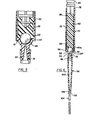
- Figs. 1 through 5 show a device embodying the concepts of the invention, including a housing 10 having generally cylindrical, longitudinally extending side walls 12, and inlet means 14 at one end of the housing and a plunger opening 16 at the other end of the housing.
- the inlet means 14 includes a nipple portion 18 integral with the side walls 12 with an opening 20 therethrough, through which a fluid may pass into the housing 10 when the device is in operation.
- Defining the bottom or end wall of the housing 10 is a wall portion 22 having a substantially hemispherical surface 24.
- a substantially spherical bead 26 Positioned within the housing 10 is a substantially spherical bead 26 which is dimensioned essentially to correspond to the shape of the surface 24, so that when the bead 26 is seated in substantial contact with the surface 24, there is substantially zero volume existing between the bead 26 and the surface 24.
- a plunger which includes a head portion 30 formed of a resilient elastomeric material, for example a rubber such as isoprene.
- the head portion 30 includes a plurality of ribs 32 which are in a wiper engagement with the interior surface of the walls 12 of the housing to ensure a fluid-tight seal therebetween.
- the plunger 28 also includes an elongated shaft 34 having an actuator handle or knob 36 on the end thereof which can be gripped, either manually or in an automated fashion, to actuate the plunger 28 and move it longitudinally within the housing 10.
- the elongated shaft 34 of the plunger 28 is of a different material than the head portion 30, being composed, for example, of a relatively inert polymeric material such as polypropylene or polyethylene.
- the plunger 28 also includes a mounting element 38 including a central shaft 40 and a mounting head 42.
- the mounting head 42 includes a pair of flanges 44 and 46 disposed to each other at right angles thereby to secure the deformable head portion 30 to the elongated shaft 34 of the plunger 28.
- the device in the embodiment of the invention shown in Figs. 1-5, includes a pipette section 48 in the form of an alongated tuoe having a tapered central base 50 adapted to frictionally and releasably engage the nipple portion 18 of the inlet means 14.
- the pipette section 48 includes a gripping flange 52 having a serrated edge on at least a portion of its periphery to permit the pipette section 48 to be gripped and twisted to release its frictional engagement with the nipple portion 18.
- the pipette section 48 also includes an inlet tube 54 which is frictionally engaged by a generally tapered opening 56 at the downstream end 58 of the pipette section 48.
- the inlet tube 54 thus permits, when the device shown is in use, a liquid sample (not shown) to be drawn into the device without contamination of the remainder of the device.
- the housing 10 also has a serrated edge 61 on at least a portion of its periphery, opposite the serrated edge of the gripping flange 52, for facilitating ease of release of the frictional engagement of the pipette section 48 with the nipple portion 18.
- the bead 26 positioned within the housing can be, for example, coated with a coating of a receptor for a particular antigen suspected of being in a sample being assayed.
- a receptor for a particular antigen suspected of being in a sample being assayed Such antigen receptors are themselves well known to those skilled in the art, and form no part of the present invention, as are well-known methodologies for coating sucn receptors onto such a bead.
- the plunger 28 is depressed fully into the housing 10 (Fig. 5). Because the head portion 30 of the plunger is deforma 5 le, the portion 30 deforms around and assumes substantially the same contour as the bead 26. It is important to this embodiment of the present invention that the head portion 30 so deform because it is important to the success of the assay that the volume in the housing 10 adjacent the bead 26 be essentially zero when the plunder 28 is fully depressed; this situation can only occur, in this embodiment, if the head portion 30 is capable of such deformation.
- the inlet tube 54 is positioned in a serum sample (not shown) containing the antigen being assayed, and the plunger 28 is withdrawn from the housing, by means of the actuating knob 36, to draw into the pipette section 48 through inlet tube 54 a measured amount of the serum sample.
- a serum sample not shown
- the plunger 28 is withdrawn from the housing, by means of the actuating knob 36, to draw into the pipette section 48 through inlet tube 54 a measured amount of the serum sample.
- the inlet tube 54 can be removed, and indeed the bottom portion of the pipette section 48 can be sealed, if desired. It is important, however, that the sample in the pipette section 48 be retained therein and not contact the bead 26 until the desired time, because the reactions which take place between antigen in the sample and the coating on the bead 26 are time-dependent chemical reactions.
- the sealed pipette section 48 is opened, if necessary, and then the plunger 28 is partially withdrawn from the housing 10 by means of the knob 36, thereby to draw the sample from the pipette section 48 into tne housing 10 for contact with the bead 26. Such contact usually occurs under controlled temperature (incubation) and for a measured period of time. The pipette section 48 can then be removed and discarded, if desired.
- the plunger actuator knob 36 is depressed to fully depress the plunger 28 and to expel from the housing 10 the serum sample, leaving antigen from the sample chemically oound or immobilized on the coating on the bead 26.
- the substantially hemispherical surface 24 include a plurality of grooves therein 60 (Fig. 4) to provide passage means between the surface 24 and the bead 26 through which any liquid remaining can be drained and expelled from the housing 10.
- the bead 26 is washed by providing to the nipple portion 14 a source of wash water (not shown) which is drawn into the housing 10 through tne passage 20 to wash any remaining serum from the bead 26, again leaving the antigen bound or immobilized upon the coating on the bead 26.
- the passage 20 preferably has a conical or tapered configuration to create turbulence in the fluid being drawn through the housing 10 as the plunger 28 is withdrawn.
- the plunger 28 is withdrawn from a portion of the housing 10 to draw the wash water into the housing 12 to wash the bead 26, as described above.
- the wash water is expelled from the housing 10 by again fully depressing the plunger 28 to the full extent to again create essentially zero volume in the housing 10 as the head portion 30 of the plunger 28 is deformed about the bead 26.
- the plunger 28 is again actuated by means of actuating knob 36 to draw into the housing 10 a measured amount of an enzyme labeled antibody solution, which is contacted in the housing 10 with the bead 26 to chemically react with the antigen bound to the coating on the bead 26.
- the enzyme labeled antibody solution is allowed to contact for a measured time the surface coating on the bead 26, it is expelled by again fully depressing the plunger 28 to reduce the volume in the housing 10 to essentially zero, and the bead 26 is again washed in the same manner as described above.
- the last reagent a chromophore reagent
- a chromophore reagent is drawn into the housing 10, by again actuating the plunger 28 as aforedescrioed, for reaction to the presence of the antigen-enzyme labeled antibody coating on the bead 26.
- the chromophore develops color in response to the presence of the enzyme, as a measure of tne antigen concentration in the serum.
- the color thus developed in the solution contained in the housing 10 can be measured by means well known to tnose skilled in the art, such as spectrophotometrically, to ascertain the concentration of antigen present in the original sample.
- This preferred device comprises a housing 70 having generally cylindrical, longitudinally-extending side walls 72, and inlet means 74 at one end of the housing 70 and a plunger opening 76 at the other end.
- the inlet means 74 includes a nipple portion 78 integral with the side walls 72 with an opening 80 therethrough, through which a fluid may pass when the device is in operation.
- Defining tne bottom or end wall of the housing 70 is a wall portion 82 having a substantially hemispherical surface 84.
- a substantially spherical oead 86 wnich is dimensioned to correspond to the shape of the surface 84, so that when the bead 86 is seated in substantial contact with the surface 84, there is essentially zero volume existing between the bead 86 and the surface 84.
- a plunger which includes a head end 90 and an elongated shaft-92 having an actuator handle or knoo 94 on the end thereof which can be gripped, either manually or in an automated fashion, to actuate the plunger 88 and move it longitudinally within the housing 70.
- the head end 90 includes ribs 96 which are in wiper engagement with the interior surface of the walls 72 of the housing 70 to ensure a fluid-tight seal therebetween.
- tne plunger 88 is formed of a relatively inert polymeric material such as polypropylene, and is of one-piece construction, tne head end 90 having a hemispherically shaped surface 90a substantially corresponding to the shape of the bead 86.
- the steps of wnich assay can be substantially as previously described with respect to the device shown in Figs. 1-5, when the plunger 88 is fully depressed, essentially zero volume is achieved within the housing 70 because the hemispherical surface 90a substantially contacts the bead 86 and, substantially conforming to the shape thereof, provides essentially no space within the housing 70 in which fluid can remain.
- the device also includes a pipette section 98 in the form of an elongated tube having a tapered central bore 100 adapted to frictionally engage the nipple portion 78 of the inlet means 74.
- the pipette section 98 further includes a gripping flange 102 having a serrated edge on at least a portion of its periphery to permit the pipette section 98 to be gripped and twisted to release its frictional engagement with the nipple portion 78.
- the pipette section 98 also includes an inlet tube 104 which is frictionally engaged by a generally tapered opening 106 at tne downstream end 108 of the pipette section 98. ' As previously described with respect to the device of Figs. 1-5, the inlet tube 104 functions, in use, to permit liquid (not shown) to be drawn into the device.
- Fig. 6 operation of the preferred device of the invention shown in Fig. 6 to perform, for example, an immunoassay on a serum sample, is accomplished in substantially the same manner as previously described for use of the device shown and described with reference to Figs. 1-5.
- this preferred device differs from the device of Figs. 1-5 in having a one-piece plunger instruction, wherein the head end 90 of the plunger 88 is not made of an elastomeric material which is deformable around tne bead 86, but rather conforms to the shape thereof because of the shape of the surface 90a.
- the head end 90 of the plunger 88 is of the same material as the shaft 92 only is advantageously molded, during its fabrication, to be integral therewith. Accordingly; while an assay can be performed in this preferred device substantially as previously described, this preferred device possesses a simpler structure which, because of its internal configuration, in use enables the advantages aforementioned, while permitting the device to be advantageously assembled witn fewer components.
- devices of the invention may be employed in such assays as dual sequential enzyme assays for various analytes, in direct assays for various ions in fluids such as water, blood or urine, or for many other uses. All such uses are within the scope of application of the present invention, and it is to oe appreciated that tnis invention, especially in view of the aforedescribed advantages thereof can have a myriad of applications.
- the device of the present invention enables the entire series of chemical reactions and changes which are necessary in the performance of an assay to take place in a single reaction chamber, namely, for example, within the housing 10 of the device of the invention illustrated in Figs. 1-5, or within the housing 70 of the preferred device shown in Fig. 6.
- the device can be used either manually, e.g., by a laboratory technician, or can be employed in automated equipment capable of processing large quantities of such devices to perform assays in a continuous manner.
- Such automated equipment while not part of the present disclosure, can be of a type designed to effect programmed manipulation of the plunger of the device in response to a sequence of steps in an assay procedure which have been set by electronic control means associated therewith.
Applications Claiming Priority (2)
| Application Number | Priority Date | Filing Date | Title |
|---|---|---|---|
| US66310084A | 1984-10-19 | 1984-10-19 | |
| US663100 | 1984-10-19 |
Publications (2)
| Publication Number | Publication Date |
|---|---|
| EP0178568A2 true EP0178568A2 (de) | 1986-04-23 |
| EP0178568A3 EP0178568A3 (de) | 1987-07-01 |
Family
ID=24660473
Family Applications (1)
| Application Number | Title | Priority Date | Filing Date |
|---|---|---|---|
| EP85112704A Withdrawn EP0178568A3 (de) | 1984-10-19 | 1985-10-08 | Vorrichtung zur Probeentnahme |
Country Status (3)
| Country | Link |
|---|---|
| EP (1) | EP0178568A3 (de) |
| JP (1) | JPS6199866A (de) |
| KR (1) | KR860003511A (de) |
Cited By (2)
| Publication number | Priority date | Publication date | Assignee | Title |
|---|---|---|---|---|
| WO1988003778A1 (fr) * | 1986-11-27 | 1988-06-02 | Jacques Chaoulli | Appareil pour prelevement et injection de liquides |
| EP0575917A2 (de) * | 1992-06-22 | 1993-12-29 | PVB MEDIZINTECHNIK GmbH | Blutentnahme-Vorrichtung |
Citations (4)
| Publication number | Priority date | Publication date | Assignee | Title |
|---|---|---|---|---|
| FR1242553A (fr) * | 1958-12-04 | 1960-09-30 | Seringue à usage médical | |
| US3734358A (en) * | 1971-07-27 | 1973-05-22 | Gen Electric | Means for applying suction having automatic cutoff of displacement volume |
| WO1984002004A1 (en) * | 1982-11-15 | 1984-05-24 | Quidel | Integrated single tube plunger immunoassay system |
| EP0109970A1 (de) * | 1982-11-29 | 1984-06-13 | Frank W. Anastasio | Blutentnahme-Einheit |
-
1985
- 1985-10-08 EP EP85112704A patent/EP0178568A3/de not_active Withdrawn
- 1985-10-18 KR KR1019850007681A patent/KR860003511A/ko not_active Application Discontinuation
- 1985-10-18 JP JP60231437A patent/JPS6199866A/ja active Pending
Patent Citations (4)
| Publication number | Priority date | Publication date | Assignee | Title |
|---|---|---|---|---|
| FR1242553A (fr) * | 1958-12-04 | 1960-09-30 | Seringue à usage médical | |
| US3734358A (en) * | 1971-07-27 | 1973-05-22 | Gen Electric | Means for applying suction having automatic cutoff of displacement volume |
| WO1984002004A1 (en) * | 1982-11-15 | 1984-05-24 | Quidel | Integrated single tube plunger immunoassay system |
| EP0109970A1 (de) * | 1982-11-29 | 1984-06-13 | Frank W. Anastasio | Blutentnahme-Einheit |
Cited By (3)
| Publication number | Priority date | Publication date | Assignee | Title |
|---|---|---|---|---|
| WO1988003778A1 (fr) * | 1986-11-27 | 1988-06-02 | Jacques Chaoulli | Appareil pour prelevement et injection de liquides |
| EP0575917A2 (de) * | 1992-06-22 | 1993-12-29 | PVB MEDIZINTECHNIK GmbH | Blutentnahme-Vorrichtung |
| EP0575917A3 (en) * | 1992-06-22 | 1996-09-18 | Pvb Medizintechnik Gmbh | Blood sampling device |
Also Published As
| Publication number | Publication date |
|---|---|
| JPS6199866A (ja) | 1986-05-17 |
| EP0178568A3 (de) | 1987-07-01 |
| KR860003511A (ko) | 1986-05-26 |
Similar Documents
| Publication | Publication Date | Title |
|---|---|---|
| JP2731613B2 (ja) | 酵素免疫測定用カートリツジ、それを用いた測定方法及び測定装置 | |
| KR100562179B1 (ko) | 중공형 절두체를 사용하는 분석물 농도 측정방법 | |
| KR100562178B1 (ko) | 중공형 절두체 시약 테스트 디바이스 | |
| EP0204109B1 (de) | Unabhängiger Reagenspaketapparat für eine Probe | |
| US6120733A (en) | Self-contained assay device | |
| EP0206561B1 (de) | Diagnostischer Apparat | |
| EP0681699B1 (de) | Festphase-immunoassay mit trägern die der form der probenlöcher entsprechen | |
| CN108136397B (zh) | 确定血液样品中的分析物的量的方法以及医疗系统 | |
| US5316732A (en) | Extraction vial | |
| EP0281201A1 (de) | Integriertes Immunoassayelement | |
| EP0320240A1 (de) | Ein Gerät zu analytischen Bestimmungen | |
| KR101923278B1 (ko) | 모세관 구조물을 가진 채혈 장치 | |
| CA2724243A1 (en) | Device and method for separating and analyzing blood | |
| JPH07287019A (ja) | 反応連鎖の無汚染処理装置および方法 | |
| US5427739A (en) | Apparatus for performing immunoassays | |
| CA2022445C (en) | Snap cap | |
| RU2554665C2 (ru) | Картридж для реагентов, используемый в устройстве для выполнения клинико-химического или твердофазного иммуноферментного анализа, применение данного картриджа и указанное устройство | |
| JPS61265570A (ja) | 化学分析用器具 | |
| US20030007892A1 (en) | UA cup | |
| EP3231513A1 (de) | Messung eines analyten mit einer kartusche | |
| EP0178568A2 (de) | Vorrichtung zur Probeentnahme | |
| US20040184965A1 (en) | Testing cup | |
| US4073620A (en) | Binder-substrate analyzer | |
| JP2002090362A (ja) | 分析のための生物学的流体の保持容器 | |
| EP0327786A1 (de) | Verfahren und Gerät zur Durchführung chemischer und biochemischer Reaktionen in porösen Trägerphasen |
Legal Events
| Date | Code | Title | Description |
|---|---|---|---|
| PUAI | Public reference made under article 153(3) epc to a published international application that has entered the european phase |
Free format text: ORIGINAL CODE: 0009012 |
|
| AK | Designated contracting states |
Kind code of ref document: A2 Designated state(s): BE CH DE FR GB IT LI NL SE |
|
| PUAL | Search report despatched |
Free format text: ORIGINAL CODE: 0009013 |
|
| AK | Designated contracting states |
Kind code of ref document: A3 Designated state(s): BE CH DE FR GB IT LI NL SE |
|
| STAA | Information on the status of an ep patent application or granted ep patent |
Free format text: STATUS: THE APPLICATION IS DEEMED TO BE WITHDRAWN |
|
| 18D | Application deemed to be withdrawn |
Effective date: 19880105 |
|
| RIN1 | Information on inventor provided before grant (corrected) |
Inventor name: VCELKA, JOHN L. Inventor name: PARSONS, ROBERT G. Inventor name: VER LEE, DONALD J. Inventor name: HOUSEMAN, KENNETH R. |