EP0178437A1 - Circuit programmable réalisé en technique CMOS dynamique - Google Patents
Circuit programmable réalisé en technique CMOS dynamique Download PDFInfo
- Publication number
- EP0178437A1 EP0178437A1 EP85111040A EP85111040A EP0178437A1 EP 0178437 A1 EP0178437 A1 EP 0178437A1 EP 85111040 A EP85111040 A EP 85111040A EP 85111040 A EP85111040 A EP 85111040A EP 0178437 A1 EP0178437 A1 EP 0178437A1
- Authority
- EP
- European Patent Office
- Prior art keywords
- level
- clock
- clock signal
- tvz
- circuit
- Prior art date
- Legal status (The legal status is an assumption and is not a legal conclusion. Google has not performed a legal analysis and makes no representation as to the accuracy of the status listed.)
- Ceased
Links
Images

Classifications
-
- H—ELECTRICITY
- H03—ELECTRONIC CIRCUITRY
- H03K—PULSE TECHNIQUE
- H03K19/00—Logic circuits, i.e. having at least two inputs acting on one output; Inverting circuits
- H03K19/02—Logic circuits, i.e. having at least two inputs acting on one output; Inverting circuits using specified components
- H03K19/173—Logic circuits, i.e. having at least two inputs acting on one output; Inverting circuits using specified components using elementary logic circuits as components
- H03K19/177—Logic circuits, i.e. having at least two inputs acting on one output; Inverting circuits using specified components using elementary logic circuits as components arranged in matrix form
- H03K19/17704—Logic circuits, i.e. having at least two inputs acting on one output; Inverting circuits using specified components using elementary logic circuits as components arranged in matrix form the logic functions being realised by the interconnection of rows and columns
- H03K19/17708—Logic circuits, i.e. having at least two inputs acting on one output; Inverting circuits using specified components using elementary logic circuits as components arranged in matrix form the logic functions being realised by the interconnection of rows and columns using an AND matrix followed by an OR matrix, i.e. programmable logic arrays
- H03K19/17716—Logic circuits, i.e. having at least two inputs acting on one output; Inverting circuits using specified components using elementary logic circuits as components arranged in matrix form the logic functions being realised by the interconnection of rows and columns using an AND matrix followed by an OR matrix, i.e. programmable logic arrays with synchronous operation, i.e. using clock signals, e.g. of I/O or coupling register
- H03K19/1772—Logic circuits, i.e. having at least two inputs acting on one output; Inverting circuits using specified components using elementary logic circuits as components arranged in matrix form the logic functions being realised by the interconnection of rows and columns using an AND matrix followed by an OR matrix, i.e. programmable logic arrays with synchronous operation, i.e. using clock signals, e.g. of I/O or coupling register with synchronous operation of at least one of the logical matrixes
Definitions
- the invention relates to a programmable circuit in dynamic C-MOS technology with an AND level, which summarizes input signals to product terms, and with an OR level, which combines the product terms to sum terms, in which the AND level to generate a Product term signal or the OR level for generating a sum term signal each have a subcircuit with two lines, one of which is used for precharging, one via a clock transistor driven by a clock transistor with a first operating potential and the other via a second clock transistor complementarily designed by a clock signal with one can be connected to the second operating potential, and has link transistors arranged between the lines and driven by the input signals or product term signals.
- Programmable circuits abbreviated PLA
- PLA Programmable circuits
- Programmable circuits can be constructed as static circuits in C-MOS technology and then have series circuits of transistors because of the complementary structure. Therefore, they are not only area-intensive, but also slow.
- C-MOS-PLAs only dynamic circuit technology can be considered.
- the AND level and the OR level of the PLA the product or sum terms of the PLA are preloaded in one clock phase (precharge phase), in the other clock phase (processing phase) depending on the logical state of the However, the input signals fed to the AND level may be discharged. A premature, and therefore false
- the two levels of the PLA must be controlled with separate clock signals that are shifted in phase with respect to each other.
- the clock signal for the OR level may only switch from precharging to processing when all product terms of the AND level have been generated safely. However, this switching time depends on the circuit design, the size and the assignment of the PLA.
- the clock signals for the AND level and for the OR level of the PLA can be generated externally. Then, however, the circuit designer must ensure that the phase shift of the two clock signals is large enough to ensure reliable functioning in the case of individual PLAs.
- the object on which the invention is based is to generate the clock signals for the OR level on the PLA itself in such a way that the clock signal for the OR level only switches from the precharge phase to the processing phase when the AND level generates all product terms Has.
- a clock delay circuit is arranged in parallel with the subcircuits of the AND level to generate the clock signal for the subcircuits of the OR level, and is constructed in accordance with the subcircuits of the AND level is driven by the clock signal for the AND level and outputs at the output a clock signal for the OR level which is delayed in relation to the clock signal for the AND level such that all sub-circuits of the AND level are switched before switching from the precharge phase to the processing phase have generated their product term signals.
- the clock delay circuit consists of two lines, one of which can be connected to the second operating potential for precharging via a clock transistor driven by the clock signal for the AND level with the first operating potential and the other via a complementary clock transistor driven by the same clock signal, and from transistors arranged between the two lines, at least one of which is constantly controlled to discharge the precharged line for generating the clock signal for the OR level.
- the delay time for the clock signal for the OR level corresponds at least to that of the slowest product term if a transistor is arranged in the clock delay circuit between the lines for each input line pair of the AND level.
- a capacitor can additionally be arranged on the line in the delay circuit, which is discharged by the transistor.
- clock delay circuit For clock lines with a not insignificant signal delay (e.g. polysilicon), it is necessary to arrange the clock delay circuit on the side of the AND level which is furthest from the point at which the clock signal for the AND level is supplied. This ensures that the clock delay circuit is triggered last when the clock signal changes state for the AND level.
- a not insignificant signal delay e.g. polysilicon
- a clocked register should be arranged at the output of the OR level for receiving the sum term signals, then it is expedient to arrange a further clock delay circuit in parallel with the subcircuits of the OR level to generate the clock signal for this register is constructed according to the clock delay circuit in the AND level.
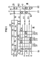
- a PLA in dynamic C-MOS technology consists of an AND level UD and an OR level 00.
- product term signals PT for example PT1 to PT3
- the OR level generates sum term signals ST, for example ST1 and ST2, from the product term signals PT1 to PT3.
- a subcircuit SE1 is provided to generate each product term signal PT.
- Each subcircuit SE1 consists of two lines L1 and L2, between which transistors TV1 are arranged.
- Line L1 is for precharging via a clock transistor TT1, in the exemplary embodiment a p-channel transistor, can be connected to a first operating potential P1.
- the line L2 can be connected to a second operating potential P2 via a clock transistor TT2, in the exemplary embodiment an n-channel transistor.
- a first clock signal TS1 for the AND level UD is supplied to the clock transistors TT1 and TT2.
- connection transistors TV1 are arranged at the crossing points between the lines for the input signals and the lines of the subcircuits SE1, as is e.g. is shown in Fig. 1.
- the lines L1 of the subcircuits SE1 are precharged with the aid of the clock signal TS1 for the AND level UD in that the clock transistor TT1 is controlled to be conductive and thus applies the operating potential P1 to the lines L1.
- the combination transistors TV1 can either discharge or not discharge the lines L1 of the subcircuits SE1 in accordance with the input signals E1 to E3 present.
- the clock transistor TT1 is blocked and the clock transistor TT2 is turned on.
- the product term signals PT1 to PT3 are thereby formed at the output of the AND level UD.
- a subcircuit SE2 is provided for generating a sum term signal ST. This consists of two lines L3 and L4, between which the link transistors TV2 are arranged in the desired manner. The control connections of this link trans toren TV2 are connected to the lines for the product term signals PT.
- One line L3 of subcircuit SE2 can be connected via a clock transistor TT1 to a first operating potential P1 for precharging, line L4 can be connected via a complementary clock transistor TT2 to an operating potential P2.
- the second clock signal TS2 for the OR level 00 is supplied to the control inputs of the clock transistors TT1 and TT2.
- the operating mode of the OR level OD is comparable to that of the AND level UD.
- the lines L3 of the subcircuits SE2 are precharged in that the clock transistor TT1 is turned on and the operating potential P1 is applied to the line L3.
- the circuit is then in the precharge phase.
- the clock signal TS2 switches, blocks the transistor TT1 and controls the transistor TT2 so that the combination transistors TV2 can discharge the lines L3 in accordance with the applied product term signals PT.
- the circuit is now in the processing phase.
- the clock delay circuit TVZ is provided. It is arranged in parallel with the subcircuits SE1 of the AND level UD and in such a way that it lies opposite the side of the AND level UD to which the clock signal TS1 is supplied.
- the clock delay Circuit TVZ is constructed in accordance with the subcircuits SE1 of the AND level UD.
- the line L5 can be connected to the operating potential P1 in accordance with the subcircuit SE1 via a clock transistor TT1.
- the line L6 can be connected to the second operating potential P2 via a clock transistor TT2 which is complementary to the clock transistor TT1.
- the clock transistors TT1 and TT2 are also driven by the clock signal TS1.
- the transistors TZO and TZ1 only one transistor, namely the transistor TZO, is continuously controlled, while the other transistors TZ1 are constantly blocked.
- the clock delay circuit TVZ is thus provided with the maximum possible capacitive load, which is only discharged via a single transistor, namely the transistor TZO.
- the clock delay circuit TVZ is in comparison to the AND level UD opposite the input for the clock signal TS1, it is ensured that the clock delay circuit is triggered after the sub-circuits SE1 when the clock signal changes state.
- the number of transistors TZO and TZ1 in the clock delay circuit TVZ is selected so that one transistor TZ is provided for each pair of input lines (input and inverted input).
- a capacitor C is connected to the line L5 in the clock delay circuit. The capacitor C causes an additional constant clock delay regardless of the size of the PLA.
- the clock signal emitted by the delay circuit TVZ must be inverted with the aid of an inverter element IG.
- a buffer circuit for the product term signals PT be arranged between the AND level UD and the OR level OD, e.g. two inverter elements IG, their effect on the product term signal can be compensated for by appropriate dimensioning of the capacitor C.
- the clock delay circuit TVZ is arranged on the same module as the rest of the PLA, the clock delay circuit TVZ is influenced by technology-related fluctuations in the circuit parameters in the same way as the OR level or the AND level. Such technology-related fluctuations are therefore taken into account when generating the clock signal TS2.
- the clock signal TS1 is fed to the AND level and the clock delay circuit TVZ.
- the transistors TT1 are controlled to be conductive and the lines L1 of the subcircuits SE1 and the line L5 of the clock delay circuit TVZ are connected to the operating potential P1. If the clock signal TS1 switches, then the processing phase AP follows. Now the clock transistors TT1 are blocked and the clock transistors TT2 are controlled to conduct and switch the second operating potential P2 to the lines L2 of the subcircuits SE1 and to the line L6 of the clock delay circuit TYZ.
- the discharge of line L5 can begin with this and corresponding to the combination transistors TV1 lines L1 of subcircuits SE2 are reloaded or not reloaded.
- the clock signal TS2 at the output of the clock delay circuit TVZ thus appears delayed compared to the clock signal TS1.
- the delay time t o between the clock signal TS2 and the clock signal TS1 can be set in such a way that the clock signal TS2 only passes from the precharge phase VP to the working phase AP when the Subcircuits SE1 of the AND level UD have generated their product term signals PT.
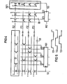
- FIG. 2 shows a slightly modified programmable circuit compared to FIG. 1.
- the difference is that p-channel transistors are now used as logic transistors TV2.
- the product term signals emitted by the AND level UD must be inverted, specifically by the inverter element IG and the signal emitted by the clock delay circuit TVZ must not be inverted. For this reason, two inverter elements are connected in series.
- the required delay time t o between the clock signal TS2 and the clock signal TS1 can again be achieved in a simple manner with the aid of the dimensioning of the capacitor C in the clock delay circuit.
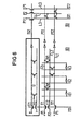
- Fig. 4 shows such a structure of a PLA.
- a clocked register RG1 is arranged at the input of the AND level UD, in which the input signals to be processed by the AND level UD are stored.
- the register RG1 is clocked by the first clocked TS1.
- a second register RG2 is arranged at the output of the OR level OD, in which the sum term signals ST are buffered. This is clocked by clock signals TS3.
- the storage may only take place when the outputs of the OR level ⁇ D are valid, that is, all the sum term signals ST have been generated. For this reason, the clock signal TS3 must occur with a time delay compared to the clock signal TS2 for the OR level OD.
- the clock signal TS3 is formed with the aid of a clock delay circuit TVZ1, which is constructed in accordance with the clock delay circuit TVZ.
- this is now arranged in parallel with the subcircuits SE2 of the OR level OD, as shown in FIG. 4. It is thus possible, as has been described for the clock delay circuit TVZ, to generate a time-delayed clock signal TS3 for the register RG2 from the clock signal TS2, as shown in FIG. 5.
- the lines L2 and L4 are combined by two adjacent subcircuits SEI and SE2, respectively, in order to save space. This doubles the capacitive load that has to be reloaded via the clock transistors TT2.
- These relationships can be simulated in the clock delay circuits TVZ and TVZ1 in that the transistors TT2 of the clock delay circuits TVZ and TVZ1 are made only half as far as the transistors TT2 of the AND level and the OR level.
Landscapes
- Physics & Mathematics (AREA)
- Mathematical Physics (AREA)
- Engineering & Computer Science (AREA)
- Computer Hardware Design (AREA)
- Computing Systems (AREA)
- General Engineering & Computer Science (AREA)
- Logic Circuits (AREA)
Applications Claiming Priority (2)
| Application Number | Priority Date | Filing Date | Title |
|---|---|---|---|
| DE3434398 | 1984-09-19 | ||
| DE3434398 | 1984-09-19 |
Publications (1)
| Publication Number | Publication Date |
|---|---|
| EP0178437A1 true EP0178437A1 (fr) | 1986-04-23 |
Family
ID=6245808
Family Applications (1)
| Application Number | Title | Priority Date | Filing Date |
|---|---|---|---|
| EP85111040A Ceased EP0178437A1 (fr) | 1984-09-19 | 1985-09-02 | Circuit programmable réalisé en technique CMOS dynamique |
Country Status (1)
| Country | Link |
|---|---|
| EP (1) | EP0178437A1 (fr) |
Cited By (7)
| Publication number | Priority date | Publication date | Assignee | Title |
|---|---|---|---|---|
| EP0251930A2 (fr) * | 1986-07-02 | 1988-01-07 | Digital Equipment Corporation | Circuit logique programmable auto-synchronisé avec circuit de précharge |
| EP0254474A1 (fr) * | 1986-07-23 | 1988-01-27 | AT&T Corp. | Réseau logique programmable CMOS |
| EP0256336A2 (fr) * | 1986-08-13 | 1988-02-24 | International Business Machines Corporation | Réseau logique programmable |
| EP0258653A2 (fr) * | 1986-08-04 | 1988-03-09 | CSELT Centro Studi e Laboratori Telecomunicazioni S.p.A. | Réseaux logiques programmables dynamiques de structure NOR-NOR réalisée en technologie C-MOS |
| EP0325180A2 (fr) * | 1988-01-19 | 1989-07-26 | National Semiconductor Corporation | Réseau logique programmable statique autopréchargé |
| EP0348539A1 (fr) * | 1988-06-28 | 1990-01-03 | Deutsche ITT Industries GmbH | Réseau logique programmable CMOS |
| EP0720297B1 (fr) * | 1994-12-29 | 2001-03-07 | STMicroelectronics Limited | Réseau logique programmable travaillant à partir d'une horloge monophase |
Citations (1)
| Publication number | Priority date | Publication date | Assignee | Title |
|---|---|---|---|---|
| US3974366A (en) * | 1974-09-30 | 1976-08-10 | Siemens Aktiengesellschaft | Integrated, programmable logic arrangement |
-
1985
- 1985-09-02 EP EP85111040A patent/EP0178437A1/fr not_active Ceased
Patent Citations (1)
| Publication number | Priority date | Publication date | Assignee | Title |
|---|---|---|---|---|
| US3974366A (en) * | 1974-09-30 | 1976-08-10 | Siemens Aktiengesellschaft | Integrated, programmable logic arrangement |
Non-Patent Citations (2)
| Title |
|---|
| IBM TECHNICAL DISCLOSURE BULLETIN, Band 24, Nr. 6, November 1981, Seite 3103, New York, US; D.A. KLUGA: "Clocked PLA with dummy circuit forming clock pulse for inter-array driver with worst-case delay" * |
| IEEE JOURNAL OF SOLID-STATE CIRCUITS, Band SC-16, Nr. 2, April 1981, Seiten 103-107, IEEE, New York, US; CHONG MING LIN: "A 4mum NMOS NAND structure PLA" * |
Cited By (12)
| Publication number | Priority date | Publication date | Assignee | Title |
|---|---|---|---|---|
| EP0251930A2 (fr) * | 1986-07-02 | 1988-01-07 | Digital Equipment Corporation | Circuit logique programmable auto-synchronisé avec circuit de précharge |
| EP0251930B1 (fr) * | 1986-07-02 | 1993-09-15 | Digital Equipment Corporation | Circuit logique programmable auto-synchronisé avec circuit de précharge |
| EP0254474A1 (fr) * | 1986-07-23 | 1988-01-27 | AT&T Corp. | Réseau logique programmable CMOS |
| EP0258653A2 (fr) * | 1986-08-04 | 1988-03-09 | CSELT Centro Studi e Laboratori Telecomunicazioni S.p.A. | Réseaux logiques programmables dynamiques de structure NOR-NOR réalisée en technologie C-MOS |
| EP0258653A3 (fr) * | 1986-08-04 | 1989-10-18 | CSELT Centro Studi e Laboratori Telecomunicazioni S.p.A. | Réseaux logiques programmables dynamiques de structure NOR-NOR réalisée en technologie C-MOS |
| EP0256336A2 (fr) * | 1986-08-13 | 1988-02-24 | International Business Machines Corporation | Réseau logique programmable |
| EP0256336A3 (en) * | 1986-08-13 | 1989-11-02 | International Business Machines Corporation | An programmable logic array |
| EP0325180A2 (fr) * | 1988-01-19 | 1989-07-26 | National Semiconductor Corporation | Réseau logique programmable statique autopréchargé |
| EP0325180A3 (fr) * | 1988-01-19 | 1990-03-28 | National Semiconductor Corporation | Réseau logique programmable statique autopréchargé |
| EP0348539A1 (fr) * | 1988-06-28 | 1990-01-03 | Deutsche ITT Industries GmbH | Réseau logique programmable CMOS |
| US4990801A (en) * | 1988-06-28 | 1991-02-05 | Deutsche Itt Industries Gmbh | Internal timing circuit for a CMOS programmable logic array |
| EP0720297B1 (fr) * | 1994-12-29 | 2001-03-07 | STMicroelectronics Limited | Réseau logique programmable travaillant à partir d'une horloge monophase |
Similar Documents
| Publication | Publication Date | Title |
|---|---|---|
| DE3634686C2 (fr) | ||
| DE3413139A1 (de) | Programmierte logikanordnung mit einer hilfshochzieheinrichtung zur erhoehung der vorlaufladegeschwindigkeit | |
| DE2621577A1 (de) | Schaltung zur bereitstellung der zur steuerung einer fluessigkristall-wiedergabeanordnung erforderlichen spannungen | |
| DE4207999A1 (de) | Adresseingabepuffereinrichtung | |
| DE4041426A1 (de) | Programmierbare logikvorrichtung | |
| DE2643020A1 (de) | Schmitt-trigger | |
| EP0633662A1 (fr) | Montage pour un oscillateur en anneau | |
| EP0639309B1 (fr) | Circuit logique asynchrone pour le fonctionnement diphase | |
| DE3903486C2 (fr) | ||
| EP0178437A1 (fr) | Circuit programmable réalisé en technique CMOS dynamique | |
| DE2625351C2 (de) | Festwertspeicher-Matrixschaltung | |
| EP0217122A1 (fr) | Circuit comportant une mémoire en forme de matrice pour ajuster de façon variable le retard des signaux digitaux | |
| EP0905895B1 (fr) | Circuit de mise en forme d'impulsions | |
| EP0252999A1 (fr) | Circuit CMOS à commande d'horloge comportant au moins un interrupteur CMOS | |
| CH657487A5 (de) | Funktionsgenerator zur erzeugung einer anzahl von sich wiederholenden digitalen wellenformen. | |
| EP0231434A1 (fr) | Composant fabriqué en technologie des circuits intégrés pour la production de ces derniers | |
| DE19800578A1 (de) | Von Schwellenspannungsänderung unabhängiger Pegelschieber | |
| DE3834760C2 (fr) | ||
| EP0025855B1 (fr) | Dispositif dans l'unité de commande d'une installation des traitement des informations pour la commande d'opérations forcées | |
| DE2618760C3 (de) | Halbleiter-Speichervorrichtung | |
| DE60037415T2 (de) | Schnittstellenverriegelung für Datenpegelübertragung | |
| EP0093899B1 (fr) | Circuit pour l'adaptation d'un dispositif d'essai à un objet à l'essai | |
| DE2052519C3 (de) | Logische Schaltung | |
| DE19743347A1 (de) | RS-Flip-Flop mit Enable-Eingängen | |
| EP0489228B1 (fr) | Système d'automatisation avec un appareil de programmation et un dispositif d'automatisation |
Legal Events
| Date | Code | Title | Description |
|---|---|---|---|
| PUAI | Public reference made under article 153(3) epc to a published international application that has entered the european phase |
Free format text: ORIGINAL CODE: 0009012 |
|
| 17P | Request for examination filed |
Effective date: 19850925 |
|
| AK | Designated contracting states |
Kind code of ref document: A1 Designated state(s): AT BE CH DE FR GB IT LI NL SE |
|
| 17Q | First examination report despatched |
Effective date: 19880801 |
|
| STAA | Information on the status of an ep patent application or granted ep patent |
Free format text: STATUS: THE APPLICATION HAS BEEN REFUSED |
|
| 18R | Application refused |
Effective date: 19890730 |
|
| RIN1 | Information on inventor provided before grant (corrected) |
Inventor name: LAWITZKY, GISBERT, DR. RER. NAT. Inventor name: KUSKE, EDITHA, DIPL.-INF. Inventor name: REICHMEYER, HANS, DIPL.-ING. Inventor name: DUZY, PETER, DIPL.-ING. |