EP0177483A2 - Form of execution for the construction of high buildings, in particular for skeleton construction - Google Patents
Form of execution for the construction of high buildings, in particular for skeleton construction Download PDFInfo
- Publication number
- EP0177483A2 EP0177483A2 EP85890236A EP85890236A EP0177483A2 EP 0177483 A2 EP0177483 A2 EP 0177483A2 EP 85890236 A EP85890236 A EP 85890236A EP 85890236 A EP85890236 A EP 85890236A EP 0177483 A2 EP0177483 A2 EP 0177483A2
- Authority
- EP
- European Patent Office
- Prior art keywords
- connecting element
- beams
- construction
- concrete
- construction according
- Prior art date
- Legal status (The legal status is an assumption and is not a legal conclusion. Google has not performed a legal analysis and makes no representation as to the accuracy of the status listed.)
- Withdrawn
Links
Images
Classifications
-
- E—FIXED CONSTRUCTIONS
- E04—BUILDING
- E04B—GENERAL BUILDING CONSTRUCTIONS; WALLS, e.g. PARTITIONS; ROOFS; FLOORS; CEILINGS; INSULATION OR OTHER PROTECTION OF BUILDINGS
- E04B1/00—Constructions in general; Structures which are not restricted either to walls, e.g. partitions, or floors or ceilings or roofs
- E04B1/18—Structures comprising elongated load-supporting parts, e.g. columns, girders, skeletons
- E04B1/20—Structures comprising elongated load-supporting parts, e.g. columns, girders, skeletons the supporting parts consisting of concrete, e.g. reinforced concrete, or other stonelike material
- E04B1/21—Connections specially adapted therefor
Definitions
- the invention relates to a construction for high-rise in particular skeleton structures by means of components consisting of prefabricated iron and / or reinforced concrete beams and prefabricated reinforced concrete columns, which are aligned in the finished state with the intermediate layer of the beams and firmly connected to each other, with each concrete column at least one end face has a recess, preferably lined with a socket, into which a connecting element can be inserted.
- Such a construction is e.g. known from AT-PS 230,592.
- specially designed bushings are poured into the recesses of the columns to align and connect ⁇ the components into a supporting skeleton and centering rods for the columns on the one hand and protrusions above and below which are used by the beams, after which the knot with concrete is shed. 1
- a disadvantage of the first-mentioned design is that the production complexity of the relatively complicated, bell-shaped socket is large and that the lugs protruding from the supports are exposed to the rough construction site operation, so that they can be damaged, in particular bent, as a result of which they no longer fit into the socket and have to be aligned.
- a disadvantage of the second design is that Beams go from pillar to pillar, although with today's manufacturing processes longer beams could be manufactured more cheaply.
- the invention has for its object to combine the advantages of both designs without ' taking over their disadvantages, and to create a construction with which high-rise buildings, in particular skeleton buildings, can be erected quickly and easily.
- the connecting element consists of two parts and is arranged entirely outside the space occupied by the carrier and that at least some of the carriers are in a row in a manner known per se over at least three , neighboring concrete columns are sufficient.
- the design according to the invention enables a considerable reduction in working hours at the construction site, because beams can now be used which extend over two or more column distances.
- the reduced working time at the construction site is particularly important in winter.
- At least one of the parts of the connecting element can be inserted into the recess of the concrete column and structurally combined with it. In this way, a further reduction in working hours at the construction site is achieved.
- each part of the connecting element can have a plate, from one side of which a rod protrudes with dimensions adapted to the recess of the concrete column, and from the opposite side of which protrude feet with an angular cross section, the light dimension between two adjacent feet of one part correspond to the outer dimensions of adjacent feet of the other part of the connecting element and at least the feet of the parts of the connecting element consist of weldable material.
- the rods can be arranged in the middle of the plate.
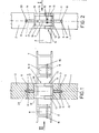
- FIG. 1 shows a section through a node formed by two columns and a support arranged one above the other
- FIG. 2 shows a view in the direction II according to FIG. 1.
- Fig. 1 shows two superimposed, prefabricated concrete columns 1, 2, of which the lower concrete column 1 on its upper end face and the upper concrete column 2 on its lower end face has an axial recess 3 or 4, which is cylindrical and preferably with a socket is lined.
- each concrete column 1, 2 is provided in the end region with a through opening 5 and 6, which runs transversely to the longitudinal axis, the purpose of which is explained later.
- the reference numeral 7 designates a lattice girder whose width is less than the column width (see FIG. 2) and which extends over at least three concrete columns 1, 2 standing side by side in a row. If the concrete columns 1, 2 are set up at equal intervals, the length of the support 7 is two or more times the simple column interval.
- ceiling beams 8 are inserted and firmly connected to the support 7, for example by means of cross holes 9 and rods 10 which are welded to the support 7. Ceiling panels (not shown) are later placed on the ceiling beams 8.
- a rod 11 In the recess 3 of the lower concrete column 1 there is a rod 11, the dimensions of which correspond to those of the recess 3 or possibly the socket.
- This rod 11 is firmly connected to a plate 12, the size of which preferably corresponds to the cross section of the concrete column 1 and in the corner regions of which one foot in the form of an angle profile 13 is attached upright.
- the rod 11, the plate 12 and the angle sections 13 are welded to steel components and.
- the plates 17 connected to the feet or angle profiles 18 of the upper part 15 can be smaller than the lower plate 12 and in any case carries on its upper side a rod 16 with the recess 4 of the upper concrete column 2 adapted dimensions.
- the width of the truss 7 is not only smaller than that of the concrete columns 1, 2, but also less than the smallest distance between the angle profiles 18 of the second, inserted part of the connecting element.
- the truss 7 can therefore pass through at the connection points of the concrete columns 1, 2.
- first several (at least three) lower, prefabricated concrete columns 1 are set up and in each of their front recesses 3 a lower part 14 of the connecting element with the rod 11 is inserted.
- Each rod 11 is provided with a bore 19 at a distance from the plate 12 corresponding to the distance of the through opening of the concrete column 1 from its end face; when inserting the rod 11 into the recess 3, this bore 19 is brought into alignment with the through opening 3, after which a wedge is introduced into the through opening 3 and the bore 19, with which the lower part 14 of the connecting element is fixed with respect to the concrete column 1.
- a truss girder 7 reaching over several concrete pillars 1 is placed on the concrete pillars 1, resting on the plates 12 of the lower parts 14 of the connecting elements and being arranged between their angle profiles 13.
- the upper parts 15 of the connecting elements are put on, overlapping the truss 7. Furthermore, the plates 17 of the upper parts 15 can rest on the truss' 7; since the knot is ultimately potted with concrete; however, this is not necessary.
- the two parts 14, 15 of the connecting elements in the illustrated embodiment by welding the angle profiles 13 and 18, are firmly connected to one another.
- the ceiling beams 8 are inserted into the trusses 7 and onto the above discussed way fixed.
- the upper concrete columns 2 with their recesses 4 are now placed on the rods 16 of the upper parts 15 of the connecting elements.
- the rods 16 of the upper parts 15 also have bores 20 aligned with the through openings 6 of the upper concrete columns 2, which are used for fixing by means of wedges - as described above. Finally, the remaining concreting work is carried out.
- the invention thus provides a construction with which a considerable reduction in working hours can be achieved at the construction site due to the beams extending over several columns, while at the same time an exact centering of the columns arranged one above the other is achieved.
- one or both parts of the connecting element can be anchored in the respective concrete column by pouring. However, because of the risk of damage to these parts mentioned at the outset, it is preferred to attach the parts to the concrete pillars only at the construction site and not during the prefabrication thereof, which is, however, quite possible.
Landscapes
- Engineering & Computer Science (AREA)
- Architecture (AREA)
- Physics & Mathematics (AREA)
- Electromagnetism (AREA)
- Civil Engineering (AREA)
- Structural Engineering (AREA)
- Joining Of Building Structures In Genera (AREA)
Abstract
Description
Die Erfindung betrifft eine Bauweise für Hoch- insbesondere Skelettbauten mittels Bauelementen, die aus vorgefertigten Eisen- und/oder Stahlbeton-Trägern sowie aus vorgefertigten bewehrten Betonsäulen bestehen, die im fertigen Zustand unter Zwischenlage der Träger ausgerichtet und fest miteinander verbunden sind, wobei jede Betonsäule an wenigstens einer Stirnfläche eine vorzugsweise mit einer Buchse ausgekleidete Ausnehmung aufweist, in die ein Verbindungselement einsetzbar ist.The invention relates to a construction for high-rise in particular skeleton structures by means of components consisting of prefabricated iron and / or reinforced concrete beams and prefabricated reinforced concrete columns, which are aligned in the finished state with the intermediate layer of the beams and firmly connected to each other, with each concrete column at least one end face has a recess, preferably lined with a socket, into which a connecting element can be inserted.
Eine derartige Bauweise ist z.B. aus der AT-PS 230.592 bekannt. Bei dieser Bauweise werden zum Ausrichten und Zusammenschließen `der Bauelemente zu einem tragenden Skelett in die Ausnehmungen der Säulen besonders ausgestaltete Buchsen eingegossen und in diese einerseits Zentrierstäbe für die Säulen und andererseits von den Trägern nach oben sowie unten vorstehende Ansätze eingesetzt, wonach der Knoten mit Beton vergossen wird. 1Such a construction is e.g. known from AT-PS 230,592. In this construction, specially designed bushings are poured into the recesses of the columns to align and connect `the components into a supporting skeleton and centering rods for the columns on the one hand and protrusions above and below which are used by the beams, after which the knot with concrete is shed. 1
Bekannt ist weiters,'als Träger Fachwerkträger vorzusehen und in die Fachwerksöffnungen Deckenbalken einzuschieben, auf welche Deckenplatten aufgelegt werden (z.B. AT-PS 235.531).It is also known to provide 'truss girders as a support and to insert ceiling beams into the truss openings on which ceiling tiles are placed (e.g. AT-PS 235.531).
Nachteilig bei der erstgenannten Bauweise ist, daß der Herstellungsaufwand der relativ kompliziert gestalteten, glockenförmigen Buchse groß ist und daß die von den Trägern abstehenden Ansätze dem rauhen Baustellenbetrieb ausgesetzt sind, sodaß sie beschädigt, insbesondere verbogen werden können, wodurch sie nicht mehr in die Buchse passen und ausgerichtet werden müssen.A disadvantage of the first-mentioned design is that the production complexity of the relatively complicated, bell-shaped socket is large and that the lugs protruding from the supports are exposed to the rough construction site operation, so that they can be damaged, in particular bent, as a result of which they no longer fit into the socket and have to be aligned.
Nachteilig bei der zweitgenannten Bauweise ist, daß die Träger von Säule zu Säule reichen, obwohl mit den heutigen Fertigungsverfahren längere Träger günstiger hergestellt werden könnten.A disadvantage of the second design is that Beams go from pillar to pillar, although with today's manufacturing processes longer beams could be manufactured more cheaply.
Der Erfindung liegt die Aufgabe zugrunde, die Vorteile beider Bauweisen zu vereinigen, ohne' deren Nachteile zu übernehmen, und eine Bauweise zu schaffen, mit der in rationeller Weise rasch und einfach Hochbauten, insbesondere Skelettbauten errichtet werden können.The invention has for its object to combine the advantages of both designs without ' taking over their disadvantages, and to create a construction with which high-rise buildings, in particular skeleton buildings, can be erected quickly and easily.
Diese Aufgabe wird mit einer Bauweise der eingangs genannten Art dadurch gelöst, daß erfindungsgemäß das Verbindungselement aus zwei Teilen besteht und zur Gänze außerhalb des vom Träger eingenommenen Raumes angeordnet ist und daß wenigstens einige der Träger in an sich bekannter Weise über zumindest drei in einer Reihe stehende, benachbarte Betonsäulen reichen.This object is achieved with a construction of the type mentioned above in that, according to the invention, the connecting element consists of two parts and is arranged entirely outside the space occupied by the carrier and that at least some of the carriers are in a row in a manner known per se over at least three , neighboring concrete columns are sufficient.
Die erfindungsgemäße Bauweise ermöglicht eine erhebliche Verkürzung der Arbeitszeit an der Baustelle, weil nunmehr Träger verwendet werden können, die über zwei oder mehr Säulenabstände reichen. Die verkürzte Arbeitszeit an der Baustelle ist besonders im Winter von Bedeutung.The design according to the invention enables a considerable reduction in working hours at the construction site, because beams can now be used which extend over two or more column distances. The reduced working time at the construction site is particularly important in winter.
In vorteilhafter Weiterbildung der Erfindung kann wenigstens einer der Teile des Verbindungselementes in die Ausnehmung der Betonsäule eingesetzt und mit dieser baulich vereinigt sein. Auf diese Weise wird eine weitere Arbeitszeitverkürzung an der Baustelle erzielt.In an advantageous development of the invention, at least one of the parts of the connecting element can be inserted into the recess of the concrete column and structurally combined with it. In this way, a further reduction in working hours at the construction site is achieved.
Ferner kann jeder Teil des Verbindungselementes eine Platte aufweisen, von deren einer Seite ein Stab mit der Ausnehmung der Betonsäule angepaßten Abmessungen absteht und von deren gegenüberliegender Seite Füße mit winkelförmigem Querschnitt vorragen, wobei das Lichtmaß zwischen zwei benachbarten Füßen des einen Teiles dem Außenmaß zugeordneter benachbarter Füße des anderen Teiles des Verbindungselementes entspricht und zumindest die Füße der Teile des Verbindungselementes aus schweißbarem Material bestehen. Dabei können die Stäbe in der Plattenmitte angeordnet sein.Furthermore, each part of the connecting element can have a plate, from one side of which a rod protrudes with dimensions adapted to the recess of the concrete column, and from the opposite side of which protrude feet with an angular cross section, the light dimension between two adjacent feet of one part correspond to the outer dimensions of adjacent feet of the other part of the connecting element and at least the feet of the parts of the connecting element consist of weldable material. The rods can be arranged in the middle of the plate.
Dies ermöglicht eine einfache Herstellung der Teile des Verbindungselementes sowie der Verbindung der Teile selbst bei genauer Zentrierung übereinander angeordneter Säulen und dazwischenliegender Träger.This enables simple production of the parts of the connecting element and the connection of the parts even with precise centering of columns arranged one above the other and supports located therebetween.
Die Erfindung wird im folgenden anhand eines bevorzugten Ausführungsbeispieles näher erläutert, das in den Zeichnungen schematisch dargestellt ist; es zeigen Fig. 1 einen Schnitt durch einen von zwei übereinander angeordneten Säulen und einem Träger gebildeten Knoten und Fig. 2 eine Ansicht in Richtung II gemäß Fig. 1.The invention is explained in more detail below with reference to a preferred exemplary embodiment which is shown schematically in the drawings; 1 shows a section through a node formed by two columns and a support arranged one above the other, and FIG. 2 shows a view in the direction II according to FIG. 1.
Fig. 1 zeigt zwei übereinander angeordnete, vorgefertigte Betonsäulen 1, 2, von denen die untere Betonsäule 1 an ihrer oberen Stirnfläche und die obere Betonsäule 2 an ihrer unteren Stirnfläche eine axiale Ausnehmung 3 bzw. 4 aufweist, die zylindrisch gestaltet und vorzugsweise mit einer Buchse ausgekleidet ist. Außerdem ist jede Betonsäule 1, 2 im Endbereich mit einer quer zur Längsachse verlaufenden Durchgangsöffnung 5 bzw. 6 versehen, deren Zweck später erläutert ist.Fig. 1 shows two superimposed,
Mit dem Bezugszeichen 7 ist ein Fachwerkträger bezeichnet, dessen Breite geringer als die Säulenbreite ist (s. Fig. 2) und der über wenigstens drei nebeneinander in einer Reihe stehende Betonsäulen 1, 2 reicht. Sind die Betonsäulen 1, 2 in gleichen Abständen aufgestellt, so beträgt die Länge des Trägers 7 das Zwei- oder Mehrfache des einfachen Säulenabstandes. In das Fachwerk des Trägers 7 sind Deckenbalken 8 eingeschoben und mit dem Träger 7 z.B. mittels Querlöcher 9 durchgesteckter und mit dem Träger 7 verschweißter Stäbe 10 fest verbunden. Auf die Deckenbalken 8 werden später (nicht gezeigte) Deckenplatten aufgelegt.The
In der Ausnehmung 3 der unteren Betonsäule 1 steckt ein Stab 11, dessen Abmessungen denjenigen der Ausnehmung 3 bzw. allfällig der Buchse entsprechen. Dieser Stab 11 ist mit einer Platte 12 fest verbunden, deren Größe vorzugsweise dem Querschnitt der Betonsäule 1 entspricht und in deren Eckbereichen je ein Fuß in Form eines Winkelprofiles 13 aufrecht befestigt ist. Insbesondere sind der Stab 11, die Platte 12 und die Winkelprofile 13 Stahlbauteile und.miteinander verschweißt. Diese Bauteile bilden den einen, unteren Teil 14 eines zweiteiligen Verbindungselementes, dessen zweiter, oberer Teil 15 gleich aufgebaut ist wie der untere Teil 14 mit der Ausnahme, daß das Außenmaß zweier Winkelprofile 18 dem Lichtmaß zwischen benachbarten Winkelprofilen 13 des unteren Teiles 14'entspricht bzw. um die doppelte Stegdicke dieser Winkelprofile 13 geringer ist, sodaß die beiden Teile 14, 15 ineinandergeschoben werden können. Die mit den Füßen bzw. Winkelprofilen 18 des oberen Teiles 15 verbundene Platte 17 kann dabei kleiner sein als die untere Platte 12 und trägt jedenfalls an ihrer Oberseite einen Stab 16 mit der Ausnehmung 4 der oberen Betonsäule 2 angepaßten Abmessungen.In the
Wie aus Fig. 2 hervorgeht, ist die Breite des Fachwerkträgers 7 nicht nur kleiner als die der Betonsäuele 1, 2, sondern auch geringer als der kleinste Abstand zwischen den Winkelprofilen 18 des zweiten, eingesteckten Teiles des Verbindungselementes. Daher kann der Fachwerksträger 7 an den Verbindungsstellen der Betonsäulen 1,2 durchlaufen.As is apparent from Fig. 2, the width of the
Gemäß der erfindungsgemäßen Bauweise werden zunächst mehrere (wenigstens drei) untere, vorgefertigte Betonsäulen 1 aufgestellt und in deren stirnseitige Ausnehmungen 3 jeweils ein unterer Teil 14 des Verbindungselementes mit dem Stab 11 eingesetzt. Jeder Stab 11 ist in einem dem Abstand der Durchgangsöffnung der Betonsäule 1 von ihrer Stirnfläche entsprechenden Abstand von der Platte 12 mit einer Bohrung 19 versehen; bei Einsetzen des Stabes 11 in die Ausnehmung 3 wird diese Bohrung 19 mit der Durchgangsöffnung 3 zum Fluchten gebracht, wonach ein Keil in die Durchgangsöffnung 3 sowie die Bohrung 19 eingeführt wird, mit dem der untere Teil 14 des Verbindungselementes bezüglich der Betonsäule 1 fixiert wird.According to the construction according to the invention, first several (at least three) lower, prefabricated concrete columns 1 are set up and in each of their front recesses 3 a
Anschließend wird ein über mehrere Betonsäulen 1 reichender Fachwerkträger 7 auf die Betonsäulen 1 aufgelegt, wobei er auf den Platten 12 der unteren Teile 14 der Verbindungselemente aufruht und zwischen deren Winkelprofilen 13 angeordnet ist.Subsequently, a
Danach werden die oberen Teile 15 der Verbindungselemente aufgesetzt, wobei sie den Fachwerkträger 7 übergreifen. Weiters können die Platten 17 der oberen Teile 15 auf dem Fachwerkträger '7 aufliegen; da der Knoten letztlich mit Beton vergossen wird; ist dies aber nicht erforderlich. Nach dem Aufsetzen und Ausrichten der oberen Teile 15 werden die beiden Teile 14, 15 der Verbindungselemente, beim dargestellten Ausführungsbeispiel durch Verschweißen der Winkelprofile 13 bzw. 18, fest miteinander verbunden.Then the
Sind zwei Säulenreihen samt auf diesen aufliegenden Fachwerkträgern 7 errichtet und die Teile 14, 15 der Verbindungselemente verbunden, so werden in die Fachwerkträger 7 die Deckenbalken 8 eingesetzt und auf die vorstehend erörterte Weise fixiert.If two rows of columns, including the
Auf die Stäbe 16 der oberen Teile 15 der Verbindungselemente werden nun die oberen Betonsäulen 2 mit ihren Ausnehmungen 4 aufgesetzt. Auch die Stäbe 16 der oberen Teile 15 weisen mit den Durchgangsöffnungen 6 der oberen Betonsäulen 2 fluchtende Bohrungen 20 auf, die zur Fixierung mittels Keilen - wie vorstehend beschrieben - dienen. Schließlich werden die übrigen Betonierungsarbeiten durchgeführt.The
Die Erfindung schafft also eine Bauweise, mit der aufgrund der über mehrere Säulen reichenden Träger eine erhebliche Arbeitszeitverkürzung an der Baustelle erzielbar ist, wobei zugleich eine genaue Zentrierung der übereinander angeordneten Säulen erreicht wird.The invention thus provides a construction with which a considerable reduction in working hours can be achieved at the construction site due to the beams extending over several columns, while at the same time an exact centering of the columns arranged one above the other is achieved.
Im Rahmen der Erfindung sind zahlreiche Abwandlungen möglich. Desgleichen können anstelle der Winkelprofile auch Füße mit anderen Querschnittsformen Verwendung finden. Schließlich können auch ein oder beide Teile des Verbindungselementes in'der jeweiligen Betonsäule durch Eingießen verankert sein. Allerdings wird wegen der eingangs erwähnten Gefahr der Beschädigung dieser Teile bevorzugt, die Teile erst an der Baustelle an den Betonsäulen zu befestigen und nicht etwa im Zuge der Vorfertigung derselben, was jedoch durchaus möglich ist.Numerous modifications are possible within the scope of the invention. Likewise, feet with other cross-sectional shapes can be used instead of the angle profiles. Finally, one or both parts of the connecting element can be anchored in the respective concrete column by pouring. However, because of the risk of damage to these parts mentioned at the outset, it is preferred to attach the parts to the concrete pillars only at the construction site and not during the prefabrication thereof, which is, however, quite possible.
Claims (7)
Applications Claiming Priority (2)
| Application Number | Priority Date | Filing Date | Title |
|---|---|---|---|
| AT3107/84 | 1984-10-01 | ||
| AT0310784A AT381526B (en) | 1984-10-01 | 1984-10-01 | CONSTRUCTION FOR TALL, IN PARTICULAR SKELETON BUILDINGS |
Publications (2)
| Publication Number | Publication Date |
|---|---|
| EP0177483A2 true EP0177483A2 (en) | 1986-04-09 |
| EP0177483A3 EP0177483A3 (en) | 1988-01-27 |
Family
ID=3545407
Family Applications (1)
| Application Number | Title | Priority Date | Filing Date |
|---|---|---|---|
| EP85890236A Withdrawn EP0177483A3 (en) | 1984-10-01 | 1985-09-26 | Form of execution for the construction of high buildings, in particular for skeleton construction |
Country Status (2)
| Country | Link |
|---|---|
| EP (1) | EP0177483A3 (en) |
| AT (1) | AT381526B (en) |
Cited By (2)
| Publication number | Priority date | Publication date | Assignee | Title |
|---|---|---|---|---|
| DE10247388A1 (en) * | 2002-10-07 | 2004-04-22 | Unterberg, Hartmut, Dipl.-Ing. (FH) | Standardized, self-supporting support structure for single is designed so that it can be expanded at any time in horizontal and vertical extents by direct connecting of additional modules to base module |
| CN110306785A (en) * | 2019-07-25 | 2019-10-08 | 河南绿建建筑科技有限公司 | Steel concrete compound shear wall T-type node formwork for placing frame |
Families Citing this family (1)
| Publication number | Priority date | Publication date | Assignee | Title |
|---|---|---|---|---|
| CN108789787B (en) * | 2018-06-03 | 2022-08-12 | 重庆工业职业技术学院 | High-efficiency construction method of high-strength assembly type building |
Citations (4)
| Publication number | Priority date | Publication date | Assignee | Title |
|---|---|---|---|---|
| AT230592B (en) * | 1961-03-06 | 1963-12-10 | Stefan Herzy | Construction for high-rise, in particular, skeleton structures |
| AT235531B (en) * | 1962-11-06 | 1964-09-10 | Stefan Herzy | Process for the production of beam ceilings |
| AU485203B2 (en) * | 1971-11-23 | 1974-03-28 | Dowsett Engineering (Australia) Pty. Limited | Interconnecting structural elements |
| EP0079413A1 (en) * | 1981-11-16 | 1983-05-25 | Geilinger AG | Arrangement of the column connection of a building |
-
1984
- 1984-10-01 AT AT0310784A patent/AT381526B/en not_active IP Right Cessation
-
1985
- 1985-09-26 EP EP85890236A patent/EP0177483A3/en not_active Withdrawn
Patent Citations (4)
| Publication number | Priority date | Publication date | Assignee | Title |
|---|---|---|---|---|
| AT230592B (en) * | 1961-03-06 | 1963-12-10 | Stefan Herzy | Construction for high-rise, in particular, skeleton structures |
| AT235531B (en) * | 1962-11-06 | 1964-09-10 | Stefan Herzy | Process for the production of beam ceilings |
| AU485203B2 (en) * | 1971-11-23 | 1974-03-28 | Dowsett Engineering (Australia) Pty. Limited | Interconnecting structural elements |
| EP0079413A1 (en) * | 1981-11-16 | 1983-05-25 | Geilinger AG | Arrangement of the column connection of a building |
Cited By (3)
| Publication number | Priority date | Publication date | Assignee | Title |
|---|---|---|---|---|
| DE10247388A1 (en) * | 2002-10-07 | 2004-04-22 | Unterberg, Hartmut, Dipl.-Ing. (FH) | Standardized, self-supporting support structure for single is designed so that it can be expanded at any time in horizontal and vertical extents by direct connecting of additional modules to base module |
| CN110306785A (en) * | 2019-07-25 | 2019-10-08 | 河南绿建建筑科技有限公司 | Steel concrete compound shear wall T-type node formwork for placing frame |
| CN110306785B (en) * | 2019-07-25 | 2024-05-17 | 河南绿建建筑科技有限公司 | T-shaped node pouring template frame for steel-concrete composite shear wall |
Also Published As
| Publication number | Publication date |
|---|---|
| AT381526B (en) | 1986-10-27 |
| EP0177483A3 (en) | 1988-01-27 |
| ATA310784A (en) | 1986-03-15 |
Similar Documents
| Publication | Publication Date | Title |
|---|---|---|
| EP1931832A2 (en) | Composite pillar for junction connections on constructions and building frames | |
| EP0073733B1 (en) | Grid-like girder for the support of underground galleries and shafts | |
| EP0752033B1 (en) | Structure consisting of prefabricated components | |
| DE3432940A1 (en) | Prefabricated masonry structure | |
| EP0177483A2 (en) | Form of execution for the construction of high buildings, in particular for skeleton construction | |
| DE3716833A1 (en) | METHOD FOR PRODUCING PRELOADED STEEL BEAMS, AND THE BEARINGS OBTAINED THEREFORE | |
| DE19941603C2 (en) | Reinforced concrete part for the production of foundations for buildings | |
| DE3704900C2 (en) | ||
| DE202005006228U1 (en) | Roof construction for buildings, especially industrial buildings with large widths, comprises bottom and top booms in the form of I-shaped supports with two boom flanges, and node elements with two flat node flange plates | |
| DE60304547T2 (en) | Prefabricated reinforced concrete column and reinforced concrete beams | |
| DE3941313A1 (en) | COMPOSITE STRUCTURE FOR A JOINT FOR SUPPORTING AN UPRISING WALL | |
| DE1998231U (en) | WALL ELEMENTS FOR ERECTING BUILDINGS AND THE LIKE | |
| EP2194202A2 (en) | Method for producing an office module | |
| DE2548298C2 (en) | Method and cavity formwork wall for building a cavity wall | |
| DE2815080A1 (en) | SCARF BODY | |
| AT399003B (en) | Girder grid for loft development or for erecting large buildings | |
| AT406592B (en) | Load-bearing construction for structures | |
| DE3513624A1 (en) | Transportable structure | |
| EP4194613A1 (en) | Structural unit for manufacturing a concrete foundation, use and method | |
| DE1817877C3 (en) | Process for the production of a transportable tree element for the erection of structures | |
| DE2257004C3 (en) | Method for producing a bridge structure from prestressed concrete | |
| DE4012532A1 (en) | Concrete component production method - uses prefabricated concrete component enclosing mould chamber and forming part of final article | |
| DE2720042A1 (en) | CONNECTING A BEAM TO A PILLAR | |
| CH645427A5 (en) | Double garage | |
| DE3312561C2 (en) | Device for connecting formwork elements of concrete formwork stacked on top of one another |
Legal Events
| Date | Code | Title | Description |
|---|---|---|---|
| PUAI | Public reference made under article 153(3) epc to a published international application that has entered the european phase |
Free format text: ORIGINAL CODE: 0009012 |
|
| AK | Designated contracting states |
Kind code of ref document: A2 Designated state(s): BE CH DE FR GB IT LI LU NL SE |
|
| PUAL | Search report despatched |
Free format text: ORIGINAL CODE: 0009013 |
|
| AK | Designated contracting states |
Kind code of ref document: A3 Designated state(s): BE CH DE FR GB IT LI LU NL SE |
|
| RHK1 | Main classification (correction) |
Ipc: E04B 1/56 |
|
| STAA | Information on the status of an ep patent application or granted ep patent |
Free format text: STATUS: THE APPLICATION IS DEEMED TO BE WITHDRAWN |
|
| 18D | Application deemed to be withdrawn |
Effective date: 19880728 |