EP0176489A2 - Tintenstrahldruckkopf, Verfahren zu seiner Herstellung und Werkzeug zur Durchführung des Verfahrens - Google Patents
Tintenstrahldruckkopf, Verfahren zu seiner Herstellung und Werkzeug zur Durchführung des Verfahrens Download PDFInfo
- Publication number
- EP0176489A2 EP0176489A2 EP85830235A EP85830235A EP0176489A2 EP 0176489 A2 EP0176489 A2 EP 0176489A2 EP 85830235 A EP85830235 A EP 85830235A EP 85830235 A EP85830235 A EP 85830235A EP 0176489 A2 EP0176489 A2 EP 0176489A2
- Authority
- EP
- European Patent Office
- Prior art keywords
- tubes
- plate member
- support
- housing
- head according
- Prior art date
- Legal status (The legal status is an assumption and is not a legal conclusion. Google has not performed a legal analysis and makes no representation as to the accuracy of the status listed.)
- Granted
Links
Images

Classifications
-
- B—PERFORMING OPERATIONS; TRANSPORTING
- B41—PRINTING; LINING MACHINES; TYPEWRITERS; STAMPS
- B41J—TYPEWRITERS; SELECTIVE PRINTING MECHANISMS, i.e. MECHANISMS PRINTING OTHERWISE THAN FROM A FORME; CORRECTION OF TYPOGRAPHICAL ERRORS
- B41J2/00—Typewriters or selective printing mechanisms characterised by the printing or marking process for which they are designed
- B41J2/005—Typewriters or selective printing mechanisms characterised by the printing or marking process for which they are designed characterised by bringing liquid or particles selectively into contact with a printing material
- B41J2/01—Ink jet
- B41J2/135—Nozzles
- B41J2/16—Production of nozzles
- B41J2/1621—Manufacturing processes
- B41J2/1632—Manufacturing processes machining
- B41J2/1634—Manufacturing processes machining laser machining
-
- B—PERFORMING OPERATIONS; TRANSPORTING
- B41—PRINTING; LINING MACHINES; TYPEWRITERS; STAMPS
- B41J—TYPEWRITERS; SELECTIVE PRINTING MECHANISMS, i.e. MECHANISMS PRINTING OTHERWISE THAN FROM A FORME; CORRECTION OF TYPOGRAPHICAL ERRORS
- B41J2/00—Typewriters or selective printing mechanisms characterised by the printing or marking process for which they are designed
- B41J2/005—Typewriters or selective printing mechanisms characterised by the printing or marking process for which they are designed characterised by bringing liquid or particles selectively into contact with a printing material
- B41J2/01—Ink jet
- B41J2/135—Nozzles
- B41J2/16—Production of nozzles
- B41J2/1607—Production of print heads with piezoelectric elements
- B41J2/1615—Production of print heads with piezoelectric elements of tubular type
-
- B—PERFORMING OPERATIONS; TRANSPORTING
- B41—PRINTING; LINING MACHINES; TYPEWRITERS; STAMPS
- B41J—TYPEWRITERS; SELECTIVE PRINTING MECHANISMS, i.e. MECHANISMS PRINTING OTHERWISE THAN FROM A FORME; CORRECTION OF TYPOGRAPHICAL ERRORS
- B41J2/00—Typewriters or selective printing mechanisms characterised by the printing or marking process for which they are designed
- B41J2/005—Typewriters or selective printing mechanisms characterised by the printing or marking process for which they are designed characterised by bringing liquid or particles selectively into contact with a printing material
- B41J2/01—Ink jet
- B41J2/135—Nozzles
- B41J2/16—Production of nozzles
- B41J2/1621—Manufacturing processes
- B41J2/1623—Manufacturing processes bonding and adhesion
-
- B—PERFORMING OPERATIONS; TRANSPORTING
- B41—PRINTING; LINING MACHINES; TYPEWRITERS; STAMPS
- B41J—TYPEWRITERS; SELECTIVE PRINTING MECHANISMS, i.e. MECHANISMS PRINTING OTHERWISE THAN FROM A FORME; CORRECTION OF TYPOGRAPHICAL ERRORS
- B41J2/00—Typewriters or selective printing mechanisms characterised by the printing or marking process for which they are designed
- B41J2/005—Typewriters or selective printing mechanisms characterised by the printing or marking process for which they are designed characterised by bringing liquid or particles selectively into contact with a printing material
- B41J2/01—Ink jet
- B41J2/135—Nozzles
- B41J2/16—Production of nozzles
- B41J2/1621—Manufacturing processes
- B41J2/1625—Manufacturing processes electroforming
-
- B—PERFORMING OPERATIONS; TRANSPORTING
- B41—PRINTING; LINING MACHINES; TYPEWRITERS; STAMPS
- B41J—TYPEWRITERS; SELECTIVE PRINTING MECHANISMS, i.e. MECHANISMS PRINTING OTHERWISE THAN FROM A FORME; CORRECTION OF TYPOGRAPHICAL ERRORS
- B41J2/00—Typewriters or selective printing mechanisms characterised by the printing or marking process for which they are designed
- B41J2/005—Typewriters or selective printing mechanisms characterised by the printing or marking process for which they are designed characterised by bringing liquid or particles selectively into contact with a printing material
- B41J2/01—Ink jet
- B41J2/135—Nozzles
- B41J2/16—Production of nozzles
- B41J2/1621—Manufacturing processes
- B41J2/1631—Manufacturing processes photolithography
-
- B—PERFORMING OPERATIONS; TRANSPORTING
- B41—PRINTING; LINING MACHINES; TYPEWRITERS; STAMPS
- B41J—TYPEWRITERS; SELECTIVE PRINTING MECHANISMS, i.e. MECHANISMS PRINTING OTHERWISE THAN FROM A FORME; CORRECTION OF TYPOGRAPHICAL ERRORS
- B41J2/00—Typewriters or selective printing mechanisms characterised by the printing or marking process for which they are designed
- B41J2/005—Typewriters or selective printing mechanisms characterised by the printing or marking process for which they are designed characterised by bringing liquid or particles selectively into contact with a printing material
- B41J2/01—Ink jet
- B41J2/135—Nozzles
- B41J2/16—Production of nozzles
- B41J2/1621—Manufacturing processes
- B41J2/1632—Manufacturing processes machining
-
- Y—GENERAL TAGGING OF NEW TECHNOLOGICAL DEVELOPMENTS; GENERAL TAGGING OF CROSS-SECTIONAL TECHNOLOGIES SPANNING OVER SEVERAL SECTIONS OF THE IPC; TECHNICAL SUBJECTS COVERED BY FORMER USPC CROSS-REFERENCE ART COLLECTIONS [XRACs] AND DIGESTS
- Y10—TECHNICAL SUBJECTS COVERED BY FORMER USPC
- Y10T—TECHNICAL SUBJECTS COVERED BY FORMER US CLASSIFICATION
- Y10T29/00—Metal working
- Y10T29/42—Piezoelectric device making
-
- Y—GENERAL TAGGING OF NEW TECHNOLOGICAL DEVELOPMENTS; GENERAL TAGGING OF CROSS-SECTIONAL TECHNOLOGIES SPANNING OVER SEVERAL SECTIONS OF THE IPC; TECHNICAL SUBJECTS COVERED BY FORMER USPC CROSS-REFERENCE ART COLLECTIONS [XRACs] AND DIGESTS
- Y10—TECHNICAL SUBJECTS COVERED BY FORMER USPC
- Y10T—TECHNICAL SUBJECTS COVERED BY FORMER US CLASSIFICATION
- Y10T29/00—Metal working
- Y10T29/49—Method of mechanical manufacture
- Y10T29/49002—Electrical device making
- Y10T29/49117—Conductor or circuit manufacturing
- Y10T29/49169—Assembling electrical component directly to terminal or elongated conductor
- Y10T29/49171—Assembling electrical component directly to terminal or elongated conductor with encapsulating
- Y10T29/49172—Assembling electrical component directly to terminal or elongated conductor with encapsulating by molding of insulating material
-
- Y—GENERAL TAGGING OF NEW TECHNOLOGICAL DEVELOPMENTS; GENERAL TAGGING OF CROSS-SECTIONAL TECHNOLOGIES SPANNING OVER SEVERAL SECTIONS OF THE IPC; TECHNICAL SUBJECTS COVERED BY FORMER USPC CROSS-REFERENCE ART COLLECTIONS [XRACs] AND DIGESTS
- Y10—TECHNICAL SUBJECTS COVERED BY FORMER USPC
- Y10T—TECHNICAL SUBJECTS COVERED BY FORMER US CLASSIFICATION
- Y10T29/00—Metal working
- Y10T29/53—Means to assemble or disassemble
- Y10T29/5313—Means to assemble electrical device
- Y10T29/53265—Means to assemble electrical device with work-holder for assembly
Definitions
- the present invention relates to ink-jet printers and is particularly concerned with an ink-jet printing head comprising a plurality of tubes having one end communicating with an ink reservoir, each tube having a corresponding associated electrical signal transducer for generating an instantaneous variation in the volume of the tube so as to cause the discharge of the ink through the other end of the tube towards a printing surface, the tubes being supported by a common support having a plate member (plate) provided with a series of nozzles aligned with the other ends of the tubes.
- plate member plate
- the tubes (generally of glass) are enclosed in a housing which protects their free ends.
- the variations in general form of the transducers are discharged on the housing and create reflected waves which limit the printing speed.
- An object of the present invention is to provide an ink jet printing head which allows very high printing speeds to be achieved even with on-demand operation.
- a further object of the present invention is to provide an answer to this problem, allowing a printing head with a plurality of capillary nozzles for the discharge of the ink to be made with reduced times and working costs, while ensuring a finished product of high quality.
- the invention also relates to a tool useable for carrying out this method.
- the characteristics of this tool are stated in Claims 28 to 30 below.
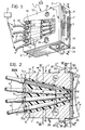
- an ink-jet printing head 1 for mounting in a printing machine, such as a high-speed printer associated with an electronic processor, personal computer, word processing system or an advanced technology typewriter, is generally indicated 1.
- the head 1 which has a generally prismatic or parallelopipedal shape, is intended to be mounted in the structure of the printing machine (not illustrated in its entirety) in a disposition such that the frontal surface of the head 1, indicated 2 in the drawings, faces a surface (normally constituted by a sheet of paper) on which it is wished to print a graphic sign.
- This graphic sign generally termed writing or printing, may be constituted by alpha-numeric characters, graphics, histograms, symbols, etc.
- the head 1 is mounted on a transversely reciprocating carriage which moves the head 1 to face successive zones arranged adjacent each line of the printing substrate.
- the ink used for the printing is taken from a reservoir, schematically indicated 3.
- the ink is conveyed to the head 1 through a plurality of flexible plastic tubes 4.
- the ink is projected towards the printing substrate through a plurality of capillary nozzles 5 located in the front part 2 of the head 1.
- the head 1 includes eight nozzles 5 arranged in an array comprising two columns each containing four nozzles, disposed parallel to each other at a distance of about 2.54 mm.
- Each column includes four nozzles about 0.846 mm apart.
- the nozzles in the two columns are staggered relative to each other by a distance of 0.423 mm, that is a distance equal to half the distance between the nozzles in each column.
- the nozzles 5 are thus able to form up to eight printed points simultaneously.
- the distances indicated and the relative disposition of the nozzles 5 are dictated by international standardization provisions and allow the printing of alpha-numeric characters reproduced on a dot-matrix basis.
- the number of points constituting each character may possibly be increased, allowing the reproduction of alpha-numeric characters of increasing clarity, the head 1 being made to scan the same region of the printing substrate in successive passes.
- the housing of the head 1 is defined by a hollow body 6 of moulded plastics material constituted by a resin (for example, that known commercially as NORIL and made by the General Electric Company) filled with glass in a proportion of about 30%.
- the body 6, which is generally flat, may be considered as being constituted by a perimetral wall 7 of roughly quadrilateral shape within which a substantially flat wall 8 ( Figure 3) constituting the core of the body 6 extends in a position approximately midway between the end edges of the wall 7.
- a flat front portion 9 illustrated in greater detail in Figure 4, and a generally circular or arcuate rear portion 10 with a centre of curvature facing towards the front portion 2 of the head.
- the rear portion 10 of the peripheral wall 7 of the body 6 has eight U-shaped notches 11 facing outwardly of the body 6 and divided into two series of four notches opening onto respective sides of the body 6.
- Each of these sides is then enclosed by a lateral wall 12 traversed by apertures 13 for the fixing of the head 1 to the drive carriage and having a wide U- or V-shaped recess 14 which renders the interior of the body 6 accessible from both sides.
- the body 6 is substantially symmetrical about the plane of the central wall 8.
- Eight tubes 15 are mounted within the body 6 for conveying ink to the nozzles 5, each tube being connected at one end to one of the tubes 4 and facing a respective nozzle 5 at its opposite end, termed the ink discharge end 16 below.
- the tubes 15 are constituted by glass ejector members formed essentially by the method described in Italian Patent Application No. 67135-A/83 by the same Applicants.
- these ejector elements may be of metal, for example nickel.
- each ink conveying tube 15 is constituted by a capillary tube 15a of glass or metal such as, for example, heatproof glass (Pyrex glass) or nickel.
- the overall length of each capillary tube 15a is about 1.5 - 2 cms, with a diameter of about 1 mm and a wall thickness of about 5 - 15 hundredths of a millimetre.
- each capillary tube 15a has a conically tapered profile extending for a length of about 4 - 5 mm and terminating with an ink discharge orifice having a diameter of about 150 ⁇ m.
- each glass capillary tube 15a is fitted a sleeve of piezo-electric material 15b which can reduce its inner diameter when a voltage pulse (generated by an electrical energisation source, not illustrated) is applied between the outer surface and the inner surface of the transducer.
- a voltage pulse generated by an electrical energisation source, not illustrated
- the dimensions and elastic characteristics of the supply tubes 4 are selected so that these tubes absorb the pressure wave generated in the ink and directed from the discharge end 16 towards the tubes 4 themselves, in order to avoid the reflection of this wave and the undesired discharge of additional ink drops (satellites).
- the ink conveying tubes 15 are mounted within the body 6 in two arrays located on opposite sides of the central wall 8. Each array includes four tubes 15 disposed, so to speak, in a rayed manner, in an arrangement such that the main axes of the tubes of each array converge towards the front wall 9 of the body 6.
- this wall has two apertures 17 in the form of slots through which the discharge ends 16 of the tubes 15 face outwardly of the body 6.
- the tubes 15 in each array lie in a single plane which is slightly inclined to the central wall 8 of the body 6 in a disposition such that (see Figure 3) the planes of the two arrays of tubes 15 converge on each other towards the front wall 9 of the body 6 itself.
- the tubes 15, and in particular their ink discharge ends 16, are embedded in a mass 18 of flexible epoxy or silicone resin constituting both a retaining mass which holds the tubes 15 in the body 6 and an insulating mass which minimises transmission of mechanical forces between the adjacent tubes. Mechanical forces resulting from the impulsive energisation of the piezo-electric transducer 15b associated with one of these tubes are thus prevented from causing the undesired emission of ink drops from adjacent tubes.
- the resin mass may be constituted, for example, by the commercial resin SILASTIC made by the Dow Corporation or the resin known as ECCOSYL RTV made by Emerson -£uming Inc.
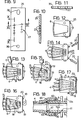
- a pair of tubular or cylindrical (pin) formations 19 for enabling it to be fitted precisely onto the housing of a ceramic or metal frontal plate member 20 having a thickness of about 0.25 mm.
- the frontal member 20 has eight circular holes, generally indicated 22, each of which (see Figure 6) constitutes a seat for receiving the ink discharge end 16 of a respective tube 15.
- the dimensions of the holes 22, however, are selected so as to be slightly greater than the transverse dimensions of the ends 16 of the duct 15 housed therein. This is in order to allow the resin 18 which is poured into the body 6 (as will be better seen below) to penetrate the annular regions between the outer wall of each end 16 and the inner wall of the corresponding hole 22 so as to effect sealing and insulation against vibrations between the end 16 and the frontal element 20.
- a further frontal member 23 constituted by a metal plate, for example of stainless steel or nickel, provided with apertures 24 for engagement with the guide pins 19 projecting from the body 6.
- the plate 23 also has eight profiled apertures each of which constitutes one of the nozzles 5 for projecting the ink ( Figure 1).
- each nozzle 5 is aligned with a corresponding hole 22 in the element 20 and consequently with the ink discharge end 16 of a respective duct 15.
- An annular sealing gasket 25 is also provided between the frontal member 20 and the frontal member 23, at least in the region surrounding each pair of aligned holes 22, 5.
- This gasket may be constituted, for example, by a layer of flexible resin such as the silicone resin SILASTIC, or by a ductile metal such as gold, tin, indium, etc.
- the shape of the apertures 21 and 24 provided in the frontal members 20 and 23 allows very high precision to be achieved in assembly of the frontal members 20 and 23, ensuring that the desired condition of alignment between the ink discharge ends 16, the holes 22 and the capillary nozzles 5 is achieved.
- the gasket 25 also allows a certain degree of translational movement between each tube 15 and the element 23 carrying the nozzles 5, which do not therefore undergo the variations produced on the ends 16 by the transducers 15b.
- the frontal elements 20 and 23 are firmly retained on the body 6 by a leaf spring 26 having a generally C shape.
- the central arm or central part of the spring 26 has apertures for the passage of the pins 19 and central elongate apertures 27 which leave uncovered the portions of the frontal member or plate 23 in which the nozzles 5 are provided.
- the lateral arms of the spring 26 have apertures 28 to allow fitting of the spring 26 on corresponding toothed formations 29 projecting laterally from the perimetral wall 7 of the body 6 adjacent the ends of the front wall 9.
- the central part of the spring 26 is arcuate in the rest condition illustrated in broken outline and indicated M in Figure 2. Consequently, when the spring 26 is fitted onto the housing 6, the central part exerts a uniform pressure on the plate 23 over its entire length. More particularly, this shape is achieved by the calculation of the deformation which this pressure would generate in a beam reproducing the central part and resting at its two ends. This shape has a radius of curvature which increases from the centre to the two ends.
- each nozzle 5 of the frontal element 23 is defined by a generally cylindrical tubular wall.
- it has a flared mouth 130 facing the end 16 of the respective tube 15 and a cylindrical portion 131 facing the end opposite the nozzle 5 (facing the printing surface), which is defined by a tubular appendage 30 projecting beyond the surface of the element 23 opposite the body 6.
- the mouth 130 is flared by about 15°, while the portion 131 has a length about equal to its diameter, which is 50-80 xxm.
- This particular conformation is designed to have a breaking effect on the ink drops which may form on the frontal surface of the head 1 between one nozzle and the adjacent one, particularly the underlying one. Moreover, it prevents the formation of the drops being disturbed by a film of ink or, in any case, by the accumulation of dirt which could result in a deterioration in the performance of the head.
- the frontal member (plate) 23 may be manufactured by various known methods.
- the frontal member 23 may be constituted by a perforated nickel plate having a thickness of the order of 50-100 microns and made by electroforming.
- a further solution is that of manufacturing the element 23 by subjecting the plates of nickel, steel or the like material to a precision spark erosion process.
- This solution allows the capillary holes 5 to be made with an internal roughness of less than a micron.
- Yet another solution provides for the manufacture of the frontal element 23 by subjecting a plate of nickel, steel or like material to a punching (micro-punching) operation similar to that used for making dies for the manufacture of synthetic fibres. A drawn area is thus formed on the outwardly-facing surface of the plate 23. This surface is then lapped to.form the holes of the nozzles with the appendages 30. The holes may then be ground by the same punch as is used for the drawing.
- a layer of light-sensitive protective material such as, for example, a layer of the photoresist made under the commercial name RISTON by the Du Pont Company.
- the layer of light-sensitive material is then exposed to light after a mask which leaves only the circular zones around the nozzles 5 uncovered has been applied to the plate. In these zones, the material polymerizes and adheres to the support. In the regions which are not exposed to light since they are masked, the light-sensitive material is not subjected to the "development" action and can then be removed easily by washing after the protective mask has been removed.
- the plate with the face intended to define the surface of the element 23 facing outwardly of the body 6 is subjected to photo-engraving to a depth of about 50 microns.
- the circular zones surrounding the nozzles 5 are not engraved since they are covered with protective material.
- A. tubular appendage constituting one of the appendages 30 is thus formed in each of these regions.
- Figure 8 illustrates schematically a possible variant of the frontal member 23.
- circular holes 32 having a diameter of the order of 0.4 - 0.6 mm are cut by a laser beam in a ceramic plate 31 having a thickness of about 0.2 mm.
- a piece of glass capillary tube 33 (of quartz silica or Pyrex glass) obtained by drawing in a process similar to that used for the manufacture of optical fibres is then inserted into each hole 32.
- Each tube 33 has an internal diameter of about 6 microns and an outer diameter of 0.3 - 0.5 mm.
- gas-chromatograph capillaries with the same dimensions may be used.
- the capillary tubes 33 are fixed within the holes 32 by gluing with epoxy resin 34.
- the capillary tubes 33 are mounted in the holes 32 so that one of the end faces of each capillary is aligned with one of the faces of the plate 31.
- This latter face of the plate 31 is intended to define that surface of the element 23 which faces towards the body 6 of the head 1.
- the other end face of each capillary 33 thus projects relative to the corresponding face of the plate 31.
- the portion of each capillary 33 between this latter face of the plate 31 and the end face of the capillary 33 projecting therefrom thus constitutes the appendage 30.
- Both the opposite surfaces of the frontal member 23 are lapped with the interposition of a metal mask made by photo-engraving or electroforming, which protects the appendages 30 and prevents their breakage during the lapping.
- the projecting end surface of each appendage 30 is then cleaned and chromium-plated so as to make it substantially non-wettable by the ink.
- a light-sensitive protective material such as RISTON allows the particularly rapid formation of the annular gaskets 25 which effect hydraulic sealing and decoupling with respect to mechanical vibrations between the two frontal members 20 and 23.
- the protective light-sensitive material polymerizes, adhering to the frontal element 23.
- the polymerized material has a certain degree of elasticity: this becomes a vibration-damping gasket around the aperture of each nozzle 5 facing the frontal member 20.
- Another solution is that of applying a layer of protective light-sensitive material to the surface of the element 23 which is intended to face the element 20, and developing the material with the use of a mask just like that used previously.
- the polymerized protective material adhere to practically the whole surface to which it has been applied, with the exception of the circular zones surrounding the apertures ofthe nozzles 5.
- the undeveloped protective material can be removed from these zones which are subsequently filled with a polymerizable material such as the silicone product known commercially as SILASTIC.
- the light-sensitive protective material is removed from the frontal member 23 and the tubular masses of SILASTIC so formed constitute the gaskets 25.
- a polymerizable resin such as SILASTIC
- a 5-10 micron layer of ductile gold, or some other ductile metal such as tin, indium,etc.
- electrolytic metal constitute the gaskets 25 in this case.
- Figure 9 illustrates a tool 35 which can be used to assemble the head 1.
- the tool 35 is constituted essentially by a plate of a metal such as brass, the overall shape of which reproduces substantially the overall shape of the frontal elements 20 and 23.
- the tool 35 has eight holes 37 the arrangement of which reproduces substantially the relative arrangement of the holes 22 and the nozzles 5.
- the plate constituting the tool 35 has a thickness of about 1 mm, that is to say, a thickness which is about five times greater than the thickness of the plate constituting the frontal member 20.
- the greater thickness of the plate 35 means that the holes 37 have an axial extent which is greater than that of the holes 22 which pass through the plate of the element 20.
- each of the holes 37 of the tool 35 defines a receiving and guide seat for the ink discharge end 16 of a respective tube 15.
- the holes 37 are arranged within the body 5 in a configuration comprising two arrays disposed in converging planes, each including, in its turn, four tubes whose ink discharge ends 16 converge, the holes 37, as best seen in Figures 10 and 11 have respective main axes inclined to the planes of the opposite parallel faces of the tool 35 itself.
- the main axis of each hole 37 is oriented to these planes at an angle of inclination, equal to the angles (in the assembled head 1) of the main axis of the corresponding tube 15 to the planes of the opposite parallel faces of the frontal member 23.
- the holes 37 are defined by frusto-conical walls which taper in the same direction as the direction of convergence of the main axes of the holes themselves.
- the conical shape of the holes 37 is intended to facilitate the introduction of the ends 16 of the tubes 15 into the holes themselves in the initial stage of the assembly of the head 1.
- the tubes 15 are mounted in the body 6 to the front wall 9 of which is applied the positioning tool 35.
- the tool 35 In its mounted position on the body 6, the tool 35 is oriented so that the greater-section ends of the holes 37 face the body 6 itself.
- Each of the tubes 15 is mounted on the body 6 ( Figure 12) in a preassembled condition, that is, with the piezo-electric transducer 15b mounted on the glass capillary 15a.
- Each tube 15 is mounted on the body 5 by the introduction of the ink discharge end 16 into a corresponding hole 37 of the positioning tool 35 and the placing of the opposite end in one of the notches 11 provided in the rear wall of the body 6.
- the tubes 15 are mounted on the body 6 in an arrangement which reproduces exactly the final disposition of use.
- the transducers 15b are subsequently fixed to the body 6 by the glue C which is applied over the whole length of the transducers 15b, care being taken not to block the tubes 15a.
- the positioning tool 35 is removed from the body 6, it being replaced by the frontal member 20 ( Figure 14).
- the application of the frontal member 20 to the body 6 is achieved without particular difficulty since the discharge ends 16 of the tubes 15 previously introduced into the holes 37 are already aligned precisely with the holes 22 in the frontal member 20.
- this frontal member is also facilitated by the presence of the pins 19 which slidingly engage the apertures 21.
- a gasket 38 of a silicone material such as SILASTIC the geometry of which reproduces substantially the geometry of the surface of the element 20 to which it is applied.
- the sole difference is due to the fact that the holes provided in the gasket 38 have a diameter of about 0.5 mm, that is, a diameter slightly less than the diameter of the holes of the frontal member 20.
- the flexible resin mass 18 intended to act as an insulator against vibrations between-the tubes 15 and the frontal plate member 20 is poured into the body 6 ( Figure 15). After pouring, the resin mass is subjected to a treatment to cause its low-temperature polymerization.
- the positioning tool 35 and the gasket 38 are finally removed from the body 6.
- the frontal surface of the head 1 defined by the surface of the element 20 opposite the body 6 is then subjected to lapping to eliminate any projections from the ends 16 of the tubes 15 and any rough edges of resin 18 projecting outwardly of the element 20 through the annular spaces between the outer surfaces of the ends 16 and the inner walls of the holes 22.
- the second frontal element 23 carrying the nozzles 5 is finally applied to the outer surface of the frontal member 20.
- the second element 23 is then clamped to the front wall of t, body 6 by the snap-engagement of the spring 26 ( Figure 17).
- the ink supply tubes 4 are connected to the rear ends of the tubes 15.
- each tube 4 is initially widened by the insertion (as shown schematically in Figure 18) of a sleeve 40, for example of nickel, having an internal diameter equal to the outer diameter of the tubes 15a and a thickness of 20-50 pm.
- a sleeve 40 for example of nickel, having an internal diameter equal to the outer diameter of the tubes 15a and a thickness of 20-50 pm.
- the edge of the tube 15a has a flare 41.
- the tube 15a is then inserted in the sleeve 40 and a ring of glue 42 is deposited in the junction zone.
- the glue penetrates between the sleeve 40 and the tube 15a and thus forms another ring in correspondence with the flare 41.
- the junction of the tube 4 and the tube 15a may be covered by a tube 44 of thermo-shrinking material which, after being heated, draws itself out so as to mechanically lock and hydraulically seal the two tubes.
Landscapes
- Engineering & Computer Science (AREA)
- Manufacturing & Machinery (AREA)
- Physics & Mathematics (AREA)
- Optics & Photonics (AREA)
- Particle Formation And Scattering Control In Inkjet Printers (AREA)
- Ink Jet (AREA)
Applications Claiming Priority (2)
| Application Number | Priority Date | Filing Date | Title |
|---|---|---|---|
| IT6795484 | 1984-09-25 | ||
| IT67954/84A IT1182285B (it) | 1984-09-25 | 1984-09-25 | Testina di stampa a getto d inchiostro relativo procedimento di fabbricazione ed attrezzo utilizzabile per l attuazione di tale procedimento |
Publications (3)
| Publication Number | Publication Date |
|---|---|
| EP0176489A2 true EP0176489A2 (de) | 1986-04-02 |
| EP0176489A3 EP0176489A3 (en) | 1987-03-11 |
| EP0176489B1 EP0176489B1 (de) | 1990-07-25 |
Family
ID=11306677
Family Applications (1)
| Application Number | Title | Priority Date | Filing Date |
|---|---|---|---|
| EP85830235A Expired - Lifetime EP0176489B1 (de) | 1984-09-25 | 1985-09-13 | Tintenstrahldruckkopf, Verfahren zu seiner Herstellung und Werkzeug zur Durchführung des Verfahrens |
Country Status (5)
| Country | Link |
|---|---|
| US (1) | US4623904A (de) |
| EP (1) | EP0176489B1 (de) |
| JP (1) | JPS6184255A (de) |
| DE (1) | DE3578853D1 (de) |
| IT (1) | IT1182285B (de) |
Cited By (1)
| Publication number | Priority date | Publication date | Assignee | Title |
|---|---|---|---|---|
| WO1990009284A1 (de) * | 1989-02-17 | 1990-08-23 | Siemens Aktiengesellschaft | Verfahren zur herstellung eines tintenschreibkopfes |
Families Citing this family (20)
| Publication number | Priority date | Publication date | Assignee | Title |
|---|---|---|---|---|
| GB8602647D0 (en) * | 1986-02-04 | 1986-03-12 | Domino Printing Sciences Plc | Ink jet droplet generator |
| IT1187936B (it) * | 1986-02-26 | 1987-12-23 | Olivetti & Co Spa | Testina di stampa mutliugello a getto d inchiostro e relativo metodo di fabbricazione |
| US4771298A (en) * | 1986-09-17 | 1988-09-13 | International Business Machine Corporation | Drop-on-demand print head using gasket fan-in |
| US4779099A (en) * | 1987-02-24 | 1988-10-18 | Dataproducts Corporation | Clamp for and method of fabricating a multi-layer ink jet apparatus |
| US4829319A (en) * | 1987-11-13 | 1989-05-09 | Hewlett-Packard Company | Plastic orifice plate for an ink jet printhead and method of manufacture |
| JP2831380B2 (ja) * | 1988-06-21 | 1998-12-02 | キヤノン株式会社 | オリフィスプレート及びインクジェット記録ヘッドの製造方法,ならびに該オリフィスプレートを用いたインクジェット記録装置 |
| KR0165677B1 (ko) * | 1989-01-20 | 1999-05-01 | 요하네스 야코부스 스모렌버그 | 잉크-제트 방식 인쇄기용 노즐 |
| US5563641A (en) * | 1994-09-23 | 1996-10-08 | Compaq Computer Corporation | Removable orifice plate for ink jet printhead and securing apparatus |
| JPH0952378A (ja) * | 1995-08-16 | 1997-02-25 | Sony Corp | プリンタ装置 |
| US5875967A (en) * | 1997-02-07 | 1999-03-02 | The Lee Company | Method and apparatus for dispensing fluid having volatile solvent |
| US6488357B2 (en) * | 2000-12-05 | 2002-12-03 | Xerox Corporation | Corrision resistant hydrophobic liquid level control plate for printhead of ink jet printer and process |
| AU2004202968B2 (en) * | 2001-01-30 | 2005-06-30 | Zamtec Limited | Inkjet printhead having nozzle guard with formations for proper alignment |
| AU2002226191B2 (en) * | 2001-01-30 | 2004-04-08 | Zamtec Limited | Nozzle guard alignment for ink jet printhead |
| AUPR277701A0 (en) * | 2001-01-30 | 2001-02-22 | Silverbrook Research Pty. Ltd. | An apparatus (art98) |
| US7163284B2 (en) * | 2001-12-12 | 2007-01-16 | Industrial Technology Research Institute | Multi-reagent inkjet cartridge |
| US7026574B2 (en) * | 2003-07-22 | 2006-04-11 | Lincoln Global, Inc. | Wire gripper for a drive unit of a wire feeder |
| US7399375B2 (en) * | 2004-12-15 | 2008-07-15 | Judson Leiser | Connecting conduits to components of fluid handling devices |
| US8733274B2 (en) * | 2006-10-20 | 2014-05-27 | Hewlett-Packard Development Company, L.P. | Tube mounted inkjet printhead die |
| US7805832B2 (en) * | 2008-08-19 | 2010-10-05 | Silverbrook Research Pty Ltd | Transfer apparatus for transferring a component of integrated circuitry |
| CN103052507B (zh) * | 2010-08-19 | 2015-01-07 | 惠普发展公司,有限责任合伙企业 | 具有盖罩的宽阵列喷墨打印头组件 |
Family Cites Families (7)
| Publication number | Priority date | Publication date | Assignee | Title |
|---|---|---|---|---|
| US4158847A (en) | 1975-09-09 | 1979-06-19 | Siemens Aktiengesellschaft | Piezoelectric operated printer head for ink-operated mosaic printer units |
| DE2930004A1 (de) * | 1979-07-24 | 1981-03-12 | Siemens AG, 1000 Berlin und 8000 München | Piezoelektrisches antriebselement fuer schreibkoepfe in tintenmosaikschreibeinrichtungen. |
| DE3019822A1 (de) | 1980-05-23 | 1981-12-03 | Siemens AG, 1000 Berlin und 8000 München | Anordnung fuer einen schreibkopf in tintenmosaikschreibeinrichtungen |
| JPS57113075A (en) | 1980-12-30 | 1982-07-14 | Fujitsu Ltd | Ink jet head |
| DE3117028A1 (de) * | 1981-04-29 | 1982-11-18 | Siemens AG, 1000 Berlin und 8000 München | Schreibkopf fuer tintenschreibeinrichtungen mit zylinderfoermigen tintenkanaelen |
| IT1144625B (it) | 1981-08-04 | 1986-10-29 | Olivetti & Co Spa | Stampante a punti a getto d inchiostro |
| DE3234408C2 (de) | 1982-09-16 | 1986-01-09 | Siemens AG, 1000 Berlin und 8000 München | Schreibkopf mit piezoelektrischen Antriebselementen für Tintenschreibeinrichtungen |
-
1984
- 1984-09-25 IT IT67954/84A patent/IT1182285B/it active
-
1985
- 1985-09-13 DE DE8585830235T patent/DE3578853D1/de not_active Expired - Lifetime
- 1985-09-13 EP EP85830235A patent/EP0176489B1/de not_active Expired - Lifetime
- 1985-09-24 JP JP60210907A patent/JPS6184255A/ja active Pending
- 1985-09-25 US US06/780,039 patent/US4623904A/en not_active Expired - Fee Related
Cited By (1)
| Publication number | Priority date | Publication date | Assignee | Title |
|---|---|---|---|---|
| WO1990009284A1 (de) * | 1989-02-17 | 1990-08-23 | Siemens Aktiengesellschaft | Verfahren zur herstellung eines tintenschreibkopfes |
Also Published As
| Publication number | Publication date |
|---|---|
| EP0176489A3 (en) | 1987-03-11 |
| JPS6184255A (ja) | 1986-04-28 |
| EP0176489B1 (de) | 1990-07-25 |
| US4623904A (en) | 1986-11-18 |
| IT1182285B (it) | 1987-10-05 |
| DE3578853D1 (de) | 1990-08-30 |
| IT8467954A0 (it) | 1984-09-25 |
Similar Documents
| Publication | Publication Date | Title |
|---|---|---|
| EP0176489B1 (de) | Tintenstrahldruckkopf, Verfahren zu seiner Herstellung und Werkzeug zur Durchführung des Verfahrens | |
| US4367480A (en) | Head device for ink jet printer | |
| EP1104697B1 (de) | Tintenstrahlaufzeichunugskopf und sein Herstellungsverfahren | |
| EP0309146B1 (de) | Verfahren zur Herstellung von Düsen für Tintenstrahldrucker | |
| CA2125250C (en) | Face shooter ink jet printing head and method for the manufacture thereof | |
| EP0339058B1 (de) | Tintenstrahlspritzdüsen | |
| JP5373712B2 (ja) | 液体噴射装置 | |
| US4364067A (en) | Highly integrated ink jet head | |
| JP3327246B2 (ja) | インクジェット記録ヘッド及びその製造方法 | |
| GB2182611A (en) | Impulse ink jet print head and methods of making the same | |
| JP3422342B2 (ja) | インクジェツト式記録ヘツド | |
| WO1983001107A1 (en) | Ink jet print head | |
| US5659343A (en) | Method of forming an ink jet recording head having an orifice plate with positioning openings for precisely locating discharge ports in a recording apparatus | |
| GB1598602A (en) | Ink jet printers | |
| US4788557A (en) | Ink jet method and apparatus for reducing cross talk | |
| US4389654A (en) | Ink jet droplet generator fabrication method | |
| EP0352468B1 (de) | Verfahren zum Herstellen einer Düsenplatte für einen Tintenstrahldruckkopf | |
| US4414552A (en) | Printing head for ink jet printers | |
| GB2037234A (en) | Jet drop printer | |
| AU740275B2 (en) | Method of producing an ink jet head | |
| EP1013452B1 (de) | Vorrichtung zur Flüssigkeitentfernung von einem Tintenstrahldrucker | |
| JP3105651B2 (ja) | インクジェットヘッドの製造方法 | |
| JPH11334069A (ja) | インクジェットヘッド | |
| US4185290A (en) | Compensation for aerodynamic drag on ink streams from a multi-nozzle ink array | |
| EP0051132B1 (de) | Erzeuger von Flüssigkeitströpfchen |
Legal Events
| Date | Code | Title | Description |
|---|---|---|---|
| PUAI | Public reference made under article 153(3) epc to a published international application that has entered the european phase |
Free format text: ORIGINAL CODE: 0009012 |
|
| AK | Designated contracting states |
Kind code of ref document: A2 Designated state(s): DE FR GB |
|
| PUAL | Search report despatched |
Free format text: ORIGINAL CODE: 0009013 |
|
| AK | Designated contracting states |
Kind code of ref document: A3 Designated state(s): DE FR GB |
|
| 17P | Request for examination filed |
Effective date: 19870826 |
|
| 17Q | First examination report despatched |
Effective date: 19890127 |
|
| GRAA | (expected) grant |
Free format text: ORIGINAL CODE: 0009210 |
|
| AK | Designated contracting states |
Kind code of ref document: B1 Designated state(s): DE FR GB |
|
| PG25 | Lapsed in a contracting state [announced via postgrant information from national office to epo] |
Ref country code: FR Effective date: 19900725 |
|
| REF | Corresponds to: |
Ref document number: 3578853 Country of ref document: DE Date of ref document: 19900830 |
|
| EN | Fr: translation not filed | ||
| PLBE | No opposition filed within time limit |
Free format text: ORIGINAL CODE: 0009261 |
|
| STAA | Information on the status of an ep patent application or granted ep patent |
Free format text: STATUS: NO OPPOSITION FILED WITHIN TIME LIMIT |
|
| 26N | No opposition filed | ||
| PGFP | Annual fee paid to national office [announced via postgrant information from national office to epo] |
Ref country code: GB Payment date: 19910805 Year of fee payment: 7 |
|
| PGFP | Annual fee paid to national office [announced via postgrant information from national office to epo] |
Ref country code: DE Payment date: 19910930 Year of fee payment: 7 |
|
| PG25 | Lapsed in a contracting state [announced via postgrant information from national office to epo] |
Ref country code: GB Effective date: 19920913 |
|
| GBPC | Gb: european patent ceased through non-payment of renewal fee |
Effective date: 19920913 |
|
| PG25 | Lapsed in a contracting state [announced via postgrant information from national office to epo] |
Ref country code: DE Effective date: 19930602 |