EP0176311B1 - Mini-Antenne - Google Patents
Mini-Antenne Download PDFInfo
- Publication number
- EP0176311B1 EP0176311B1 EP85306606A EP85306606A EP0176311B1 EP 0176311 B1 EP0176311 B1 EP 0176311B1 EP 85306606 A EP85306606 A EP 85306606A EP 85306606 A EP85306606 A EP 85306606A EP 0176311 B1 EP0176311 B1 EP 0176311B1
- Authority
- EP
- European Patent Office
- Prior art keywords
- antenna
- ground
- antenna according
- dielectric substrate
- feed point
- Prior art date
- Legal status (The legal status is an assumption and is not a legal conclusion. Google has not performed a legal analysis and makes no representation as to the accuracy of the status listed.)
- Expired - Lifetime
Links
- 230000005855 radiation Effects 0.000 claims description 42
- 239000000758 substrate Substances 0.000 claims description 27
- 230000005540 biological transmission Effects 0.000 claims description 21
- 239000004020 conductor Substances 0.000 description 10
- 230000008859 change Effects 0.000 description 3
- 238000002955 isolation Methods 0.000 description 3
- 239000002184 metal Substances 0.000 description 3
- 229910052751 metal Inorganic materials 0.000 description 3
- 230000003071 parasitic effect Effects 0.000 description 2
- 240000001492 Carallia brachiata Species 0.000 description 1
- RYGMFSIKBFXOCR-UHFFFAOYSA-N Copper Chemical compound [Cu] RYGMFSIKBFXOCR-UHFFFAOYSA-N 0.000 description 1
- 230000015556 catabolic process Effects 0.000 description 1
- 229910052802 copper Inorganic materials 0.000 description 1
- 239000010949 copper Substances 0.000 description 1
- 238000006731 degradation reaction Methods 0.000 description 1
- 230000005670 electromagnetic radiation Effects 0.000 description 1
- 238000005516 engineering process Methods 0.000 description 1
- 238000005530 etching Methods 0.000 description 1
- 239000004744 fabric Substances 0.000 description 1
- 239000003365 glass fiber Substances 0.000 description 1
- 239000000463 material Substances 0.000 description 1
- 230000004048 modification Effects 0.000 description 1
- 238000012986 modification Methods 0.000 description 1
- 230000005404 monopole Effects 0.000 description 1
- 230000035699 permeability Effects 0.000 description 1
- -1 polytetrafluoroethylene Polymers 0.000 description 1
- 229920001343 polytetrafluoroethylene Polymers 0.000 description 1
- 239000004810 polytetrafluoroethylene Substances 0.000 description 1
Images


Classifications
-
- H—ELECTRICITY
- H01—ELECTRIC ELEMENTS
- H01Q—ANTENNAS, i.e. RADIO AERIALS
- H01Q9/00—Electrically-short antennas having dimensions not more than twice the operating wavelength and consisting of conductive active radiating elements
- H01Q9/04—Resonant antennas
- H01Q9/0407—Substantially flat resonant element parallel to ground plane, e.g. patch antenna
- H01Q9/0421—Substantially flat resonant element parallel to ground plane, e.g. patch antenna with a shorting wall or a shorting pin at one end of the element
Definitions
- the present invention relates to an antenna for transmitting and/or receiving electromagnetic radiation, and more particularly to an antenna which is suitable to be used for portable radio equipment.
- factor (1) is particularly important in the case when the antenna is to be used as a build-in type.
- External sleeve antenna are usually used with portable radio equipment.
- This kind of antenna is disclosed in S.A. Schelkunoff, H.T. friis: "Antennas Theory and Practice” John Wiley & Sons (1952) at pages 475,476.
- the sleeve antenna is featured by its good electrical isolation between the antenna and the ground circuit of a coaxial transmission line and an electric circuit, where the coaxial line is used to convey energy from the transmitter to the antenna or from the antenna to the receiver.
- a quater-wave trap which is often called “balun” or “Sperrtopf" is used at a feed point of this kind of antenna.
- the sleeve antenna can be considered as a modification of a simple quater-wave monopole antenna, so that the parastic current on the outer surface of the outer conductor of the coaxial transmission line is reduced or eliminated by means of a quater-wave trap. Due to the above unique characteristics, the sleeve antenna shows fairly good performance as an external antenna for portable radio equipment. However, the antenna has to be more than one-half wavelength long, and the input impedance and gain characteristic of the antenna are easy to degrade due to access of an electric circuit and a human body to the antenna. Therefore, the sleeve antenna is not suitable as a build-in antenna for portable radio equipment.
- an antenna having a microstrip configuration is very attractive as a build-in antenna for portable radio equipment, because it is very small in size, simple form of low-plofile in shape and firm in structure.
- This kind of antenna is disclosed in IEEE Transactions on Antenna and Propagation, vol. AP-29, No. 1, pp. 1-183, January 1981.
- Fig. 5 on page 6 shows a basic structure of a rectangular microstrip antenna.
- This microstrip antenna has a sandwitch structure of two parallel conducting layers separated by a single thin dielectric substrate.
- the lower conductor functions as a ground plane, and the upper conductor may be a simple resonant rectangular patch.
- the ground plane is considered as a electrically conducting plate which is extended in X-Y plane infinitely or which has a large size relative to the wavelength of signal.
- the ground plane has to be practically as small as possible, and may be required to have almost the same size as the resonant rectangular patch. In this situation, however, the ground element no longer acts as the "ground” on which a constant potential voltage should be maintained, but a sinusoidal variation of a voltage distribution is produced on the ground plane. Therefore, if a coaxial transmission line is used to transfer signals between the antenna and the equipment, a parasitic current is generally induced on the outer conductor of the coaxial transmission line. Under this condition, the transmission line acts as a part of antenna element. As a result, the characteristics of the antenna such as the input impedance, radiation pattern and gain will change easily under actual usage conditions.
- microstrip antenna having a microstrip configuration
- a rectangular radiation element is connected to the central conductor of a coaxial cable and a ground plane element is connected to the grounded braid of the coaxial line.
- the radiation element and the ground plane elements are formed on opposite sides of a dielectric substrate and are connected together by a short circuit line in order to give a wider beam width.
- U.S.-A-4078237 discloses a quarter-wavelength antenna with shorting pins.
- the antenna has a radiation element and a ground plane element which is mentioned as being of greater length and width than the radiation element. This is no disclosure about the location about the location of the fee point on the ground plane.
- An object of the present invention is to provide a small antenna which shows electrically good isolation between the antenna and a ground circuit of a transmission line and an electric circuit so that the antenna current does not flow on the ground circuit and the case of the equipment without requiring any quarter-wave trap at a feed point.
- the present invention provides an antenna comprising: a dielectric substrate a radiation element provided on one major surface of said dielectric substrate; a ground element provided on the other major surface opposite to said one major surface of said dielectric substrate; first feed means provided at a first feed point on said radiation element for electrically connecting said radiation element with a signal line of a transmission line; and second feed means provided at a second feed point on said ground element for electrically connecting said ground element with a ground line of said transmission line, characterised by said second feed point of said second feed means being located at a position where a voltage of a standing voltage wave induced on said ground element becomes minimum.
- a feature of this antenna is that its input impedance and gain characteristic are hardly degraded due to access of an electric circuit and a human body to the antenna.
- a further feature of the antenna is that it is small in size, light in weight and high in gain so as to be suitable to be used for portable radio equipment.
- the most important feature of the antenna according to the present invention is the position of the second feed point on the ground element.
- the ground plane no longer acts as the "ground” in the case when the dimensions of the ground plane is relatively small compared to a wavelength of the signal to be transmitted.
- a sinusoidal variation of a voltage distribution, or a standing voltage wave is induced on the ground plane.
- a parasitic current is induced on the outer conductor of the coaxial transmission line.
- the outer conductor of a transmission line is connected to the ground element at the second feed point where the voltage of the standing voltage wave induced on the ground element becomes minimum.
- Each of the radiation element and the ground element of the antenna according to the present invention may be constructed in the shape of either rectangle or another shape such as a circle or an ellipse.
- the second feed point is preferably at a position apart by electrically an odd multiple of one-quarter wavelength from an end of the rectangle ground element.
- the length of the rectangular radiation element may preferably be selected to be electrically one-half wavelength long to radiate electromagnetic energy efficiently.
- the antenna according to the present invention may preferably further comprise short-circuit means which comprises a single thin conductive film or a plurality of conducting pins or via holes for electrically connecting an end of the radiation element with an end of the ground element.
- short-circuit means which comprises a single thin conductive film or a plurality of conducting pins or via holes for electrically connecting an end of the radiation element with an end of the ground element.
- the second feed point is preferably at a position apart by electrically an odd multiple of one-quarter wavelength from the end opposite to the end connected with the short-circuit means.
- the length of the rectangular radiation element may be selected to be electrically one-quarter wavelength long to radiate electromagnetic energy efficiently.
- This type of antenna has a feature that can offer a further smaller antenna because the length of the radiation element is one-quarter wavelength rather than one-half wavelength.
- the antenna according to the present invention provides a nearly omnidirectional radiation pattern in the horizontal plane with a front gain of at least -2dBd. It will be appreciated that the small antenna according to the present invention provides an antenna which is easily impedance matched to a transmission line without a quater-wave trap or an impedance matching network. Furthermore, the present invention provides an antenna which has a simple-form, firm and low-profile structure, and is particularly suited for use as a build-in antenna for portable radio equipment such as paging systems and cordless telephones.
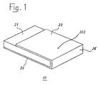
- an antenna 10 comprises a rectangular dielectric substrate 21, a radiation element 23 provided on one major surface of the dielectric substrate 21, a ground element 22 provided on the other major surface of the dielectric substrate 21, and a short-circuit element provided on a rear end surface of the dielectric substrate 21 for electrically connecting respective ends of the radiation element 23 and the ground element 22.
- the radiation element 23 and the ground element 22 are disposed parallel to each other through the dielectric substrate 21 therebetween.
- the thickness of the dielectric substrate 21, radiation and ground elements 23 and 22, and the short-circuit element 24 are exaggerated than the actual sizes.
- the actual thickness of the dielectric substrate 21 is so designed to be adequately thin relative to the signal wavelength.
- the radiation element 23, the ground element 22 and the short-circuit element 24 may be a metal film coated on the respective surfaces of the dielectric substrate 21.
- Reference numeral 203 shows a feed point on the radiation element 23.
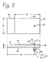
- the dielectric substrate 21 is a rectangular plate having a width E and a thickness t and made of a material which has a relative dielectric constant ⁇ .
- the metal film coated on the upper surface of the dielectric substrate 21 is partly removed by etching to form the radiation element 23 having a length D.
- Reference numerals 202 and 203 show feed points on the ground element 22 and the radiation element 23, respectively.
- a coaxial connector 25 is mounted on the lower surface of the dielectric substrate 21 at a position coincident with the feed point 202.
- An outer conductor 27 of the coaxial connector 25 is electrically connected to the ground element at the feed point 202.
- An inner conductor 26 of the coaxial connector 25 is extended upwardly through the dielectric substrate 21 to reach the radiation element 23 and electrically connected with the radiation element 23 at the feed point 203.
- a transmission line (not shown) such as a coaxial transmission line can be connected to the coaxial connector 25 to provide an electrical connection from the antenna to a transmitter and/or a receiver (not shown)
- the feed point 203 is located at a position apart by a distance F from the end connected with the short-circuit element 24 of the radiation element 23.
- the feed point 202 is located at a position apart by a distance G from the end opposite to the end connected with the short-circuit element 24 of the ground element 22.
- the resonant frequency f of the antenna is approximately given by the following equation: where C is a velocity of light, and N is a natural number.
- C is a velocity of light
- N is a natural number.
- the above equation shows that the resonant frequency f of the antenna is inversely proportional to the length D of the radiation element 23.
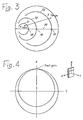
- Fig. 3 shows the complex input impedance at the feed point 203 as a function of frequency on a Smith Chart normalized to 50 ⁇ .
- Curves 31, 32 and 33 represent a change of the complex impedance locus as a function of the distance F.
- the resistive impedances 35, 36 and 37 are represented as the impedances at the points where curves 31, 32 and 33 intersect the zero-impedance line 39, respectively.
- the resistive impedance increases with the increase of the distance F, and is zero when the feed point 203 is located on the short-circuit element 24. Therefore, the distance F is determined so as to match the impedance of the antenna to the coaxial transmission line characteristic impedance, i.e. 50 ⁇ in this case.
- the width E and the thickness t of the antenna may be determined freely, but it is noted that the gain can be increased by increasing the width E and the thickness t.
- the length D of the radiation element 23 may preferably be electrically an odd multiple of one-quarter wavelength so as to radiate electromagnetic energy efficiently.
- Each of the feed points 202 and 203 may be located at any position in the widthwise direction.
- the dielectric substrate 21 is a polytetrafluoroethylene substrate reinforced with a glass fiber cloth with a relative dielectric constant ⁇ of about 2.6 and a relative permeability ⁇ of about 1.0.
- the thickness of each copper layer is about 35 ⁇ m.
- the antenna provides a nearly omnidirectional radiation pattern in the horizontal plane.
- the front gain of at least -2 dBd can be obtained.
- the front gain will increase with the increase of the width E and the thickness t.
- the input impedance and gain characteristic of the antenna will not change easily even if an electric circuit which may be electrically connected to the antenna or a human body is accessed very close to the ground element 22.
- Fig. 5 shows another embodiment of the present invention.
- a plurality of conductive pins 41 are used as the short-circuit element instead of the single metal film used in the Fig. 2 embodiment.
- the antenna shown in Fig. 5 has almost the same characteristics as those of the antenna shown in Fig. 2.
- a plurality of via holes which are coated on their inner surfaces with conductive layers may be used as the short-circuit element.
- Fig. 6 shows still another embodiment of the present invention.
- the antenna shown in Fig. 6 has no short-circuit element which connects the radiation element 23 and the ground element 22.
- the resonant frequency f of the antenna is approximately given by the following equation: where C is a velocity of light, N is a natural number, D is a length of the radiation element 23, and ⁇ is a relative dielectric constant of the dielectric substrate 21.
- the feed point 202 on the ground element 22 is placed at a position which is apart by a distance G1 from one end of the ground element 22 and by a distance G2 from the other end of the ground element 22 in the longitudinal direction of the antenna.
- Each of the distances G1 and G2 is selected to be electrically an odd multiple of one-quarter wavelength of signal to be transmitted so that the voltage of the standing voltage wave induced on the ground element 22 becomes minimum at the feed point 202.
- the length D of the radiation element 23 may preferably be selected to be electrically one-half wavelength so as to radiate electromagnetic energy efficiently.
- the antenna according to the invention can be made in any size for general applications, it is noted its structure is particularly advantageous to be configured as a small antenna used for portable radio equipment. More specifically, if the area of each major surface of the dielectric substrate is equal to or smaller than the square of the wavelength ( ⁇ 2), the antenna of the invention is more advantageous than the conventional small antennas.
Landscapes
- Waveguide Aerials (AREA)
- Details Of Aerials (AREA)
Claims (11)
- Eine Antenne enthaltend
ein dielektisches Substrat (21); ein Strahlungselement (23), das auf einer Hauptoberfläche des dielektrischen Substratsangeodnet ist; ein Erdelement (22), angeordnet auf der anderen Hauptoberfläche gegenüber der Hauptoberfläche des dielektrischen Substrats; erste Einspeisungseinrichtungen (203) an einem ersten Einspeisungspunkt an dem Strahlungselement zum elektrischen Verbinden des Strahlungselements mit einer Signalleitung einer Übertragungsleitung; und zweite Einspeisungseinrichtungen (202) an einem zweiten Einspeisungspunkt an dem Erdelement zum elektrischen Verbinden des Erdelements mit einer Erdleitung der Übertragungsleitung, dadurch gekennzeichnet daß der zweite Einspeisungspunkt der zweiten Einspeisungseinrichtungen (202) sich an einer Position befindet, wo die Spannung einer stehenden Spannungswelle, die dem Erdelement induziert wird, zu einem Minumum wird. - Eine Antenne nach Anspruch 1, bei der jedes der Strahlungselemente (23) und das Erdelement (22) eine rechteckige Form besitzt.
- Eine Antenne nach Anspruch 2, bei der der zweite Einspeisungspunkt (202) um ein elektrisch ungerades Vielfaches von einer Viertelwellenlänge eines zu übertragendes Signals von einem Ende des Erdelements (22) entfernt ist und von dem anderen Ende, entgegengesetzt zum einen Ende des Erdelements, durch ein elektrisches anderes ungerades Vielfaches einer Viertelwellenlänge des zu übertragenden Signals entfernt ist.
- Eine Antenne nach Anspruch 3, bei der die elektrische Länge des Strahlungselements (23) eine halbe Wellenlänge des zu übertragenden Signals ist.
- Eine Antenne nach Anspruch 1, die weiterhin eine Kurzschlußeinrichtung (24) an oder nahe des dielektrischen Substrats (21) zum elektrischen Verbinden des Strahlungselements (23) mit dem Erdelement (22)enthält.
- Eine Antenne nach Anspruch 5, bei der jedes Strahlungselement (23) und das Erdelement (22) von rechteckiger Form sind.
- Eine Antenne nach Anspruch 6, bei der der zweite Einspeisungspunkt (202) um ein elektisch ungerades Vielfaches einer Viertelwellenlänge des zu übertragenden Signals von einem Ende, das entgegengesetzt zum Ende, das mit der Kurschlußeinrichtung (24) des Erdelements (22) verbunden ist, entfernt ist.
- Eine Antenne nach Anspruch 7, bei der die elektrische Länge des Strahlungselements (23) eine Viertelwellenlänge des zu übertragenden Signals ist.
- Eine Antenne nach Anspruch 5, bei der die Kurzschlußeinrichtung (24) einen einzelnen leitenden Film enthält, der eine Seitenoberfläche des dielektrischen Substrats (21) beschichtet.
- Eine Antenne nach Anspruch 5, bei der die Kurzschlußeinrichtung (24) eine Vielzahl von leitfähigen Stiften (41) enthält, die nahe dem Ende des dielektrischen Substrats (21) angeordnet sind.
- Eine Antenne nach Anspruch 5, bei der der erste Einspeisungspunkt der ersten Einspeisungseinrichtungen (203) sich an einer Position befindet, an der ein Eingangsimpedanz der Antenne an eine charakteristische Impedanz der Übertragungsleitung angepaßt wird.
Applications Claiming Priority (2)
| Application Number | Priority Date | Filing Date | Title |
|---|---|---|---|
| JP59194225A JPH061848B2 (ja) | 1984-09-17 | 1984-09-17 | アンテナ |
| JP194225/84 | 1984-09-17 |
Publications (3)
| Publication Number | Publication Date |
|---|---|
| EP0176311A2 EP0176311A2 (de) | 1986-04-02 |
| EP0176311A3 EP0176311A3 (en) | 1988-07-20 |
| EP0176311B1 true EP0176311B1 (de) | 1991-11-13 |
Family
ID=16321038
Family Applications (1)
| Application Number | Title | Priority Date | Filing Date |
|---|---|---|---|
| EP85306606A Expired - Lifetime EP0176311B1 (de) | 1984-09-17 | 1985-09-17 | Mini-Antenne |
Country Status (4)
| Country | Link |
|---|---|
| US (1) | US4700194A (de) |
| EP (1) | EP0176311B1 (de) |
| JP (1) | JPH061848B2 (de) |
| DE (1) | DE3584658D1 (de) |
Families Citing this family (67)
| Publication number | Priority date | Publication date | Assignee | Title |
|---|---|---|---|---|
| DE3616723A1 (de) * | 1986-05-17 | 1987-11-19 | Philips Patentverwaltung | Mikrowellenbaustein |
| JPH0693635B2 (ja) * | 1986-12-19 | 1994-11-16 | 日本電気株式会社 | 小型無線機 |
| US4835541A (en) * | 1986-12-29 | 1989-05-30 | Ball Corporation | Near-isotropic low-profile microstrip radiator especially suited for use as a mobile vehicle antenna |
| JPH01246904A (ja) * | 1988-03-28 | 1989-10-02 | Kokusai Electric Co Ltd | 小形アンテナ |
| US4903326A (en) * | 1988-04-27 | 1990-02-20 | Motorola, Inc. | Detachable battery pack with a built-in broadband antenna |
| US4876552A (en) * | 1988-04-27 | 1989-10-24 | Motorola, Inc. | Internally mounted broadband antenna |
| JPH0646682B2 (ja) * | 1988-07-04 | 1994-06-15 | 三菱電機株式会社 | 一端短絡型マイクロストリツプアンテナ |
| US4868576A (en) * | 1988-11-02 | 1989-09-19 | Motorola, Inc. | Extendable antenna for portable cellular telephones with ground radiator |
| US4980694A (en) * | 1989-04-14 | 1990-12-25 | Goldstar Products Company, Limited | Portable communication apparatus with folded-slot edge-congruent antenna |
| US5184143A (en) * | 1989-06-01 | 1993-02-02 | Motorola, Inc. | Low profile antenna |
| US5173711A (en) * | 1989-11-27 | 1992-12-22 | Kokusai Denshin Denwa Kabushiki Kaisha | Microstrip antenna for two-frequency separate-feeding type for circularly polarized waves |
| JPH03228407A (ja) * | 1989-12-11 | 1991-10-09 | Nec Corp | アンテナおよび該アンテナを用いた携帯用無線機 |
| IT1241854B (it) * | 1990-12-31 | 1994-02-01 | Consiglio Nazionale Ricerche | Applicatori compatti su ceramica ad alta permettivita' per uso in ipertermia elettromagnetica |
| US5355142A (en) * | 1991-10-15 | 1994-10-11 | Ball Corporation | Microstrip antenna structure suitable for use in mobile radio communications and method for making same |
| EP0601576B1 (de) * | 1992-12-09 | 1999-09-01 | Matsushita Electric Industrial Co., Ltd. | Antenne für ein mobiles Kommunikationssystem |
| JPH06314924A (ja) * | 1993-04-19 | 1994-11-08 | Wireless Access Inc | 部分短絡マイクロストリップアンテナ |
| JPH06314923A (ja) * | 1993-04-19 | 1994-11-08 | Wireless Access Inc | 小型二重リングマイクロストリップアンテナ |
| AU7372594A (en) * | 1993-08-09 | 1995-02-28 | Motorola, Inc. | Printed circuit dipole antenna |
| BR9405603A (pt) * | 1993-09-20 | 1999-09-08 | Motorola Inc | Instalação de antena adaptada para dispositivo de comunicação sem fio |
| US5420596A (en) * | 1993-11-26 | 1995-05-30 | Motorola, Inc. | Quarter-wave gap-coupled tunable strip antenna |
| AU1892895A (en) * | 1994-03-08 | 1995-09-25 | Hagenuk Telecom Gmbh | Hand-held transmitting and/or receiving apparatus |
| GB2323478B (en) * | 1994-06-11 | 1998-11-18 | Motorola Israel Ltd | Antenna and method of manufacture of a radio |
| US5483246A (en) * | 1994-10-03 | 1996-01-09 | Motorola, Inc. | Omnidirectional edge fed transmission line antenna |
| DE19504577A1 (de) * | 1995-02-11 | 1996-08-14 | Fuba Automotive Gmbh | Flachantenne |
| DE19510236A1 (de) * | 1995-03-21 | 1996-09-26 | Lindenmeier Heinz | Flächige Antenne mit niedriger Bauhöhe |
| US5657028A (en) * | 1995-03-31 | 1997-08-12 | Nokia Moblie Phones Ltd. | Small double C-patch antenna contained in a standard PC card |
| US5781158A (en) * | 1995-04-25 | 1998-07-14 | Young Hoek Ko | Electric/magnetic microstrip antenna |
| DE69623697T2 (de) * | 1995-06-15 | 2003-06-05 | Nokia Corp | Ebene und nichtebene doppel-C-förmige Streifenleiterantennen mit unterschiedlichen Öffnungsformen |
| US5627550A (en) * | 1995-06-15 | 1997-05-06 | Nokia Mobile Phones Ltd. | Wideband double C-patch antenna including gap-coupled parasitic elements |
| US5680144A (en) * | 1996-03-13 | 1997-10-21 | Nokia Mobile Phones Limited | Wideband, stacked double C-patch antenna having gap-coupled parasitic elements |
| US5995048A (en) * | 1996-05-31 | 1999-11-30 | Lucent Technologies Inc. | Quarter wave patch antenna |
| DE19638874A1 (de) * | 1996-09-23 | 1998-03-26 | Rothe Lutz Dr Ing Habil | Mobilfunk-Planarantenne |
| DE59702294D1 (de) * | 1996-09-23 | 2000-10-05 | Lutz Rothe | Mobilfunk-planarantenne |
| US5945950A (en) * | 1996-10-18 | 1999-08-31 | Arizona Board Of Regents | Stacked microstrip antenna for wireless communication |
| US6049278A (en) * | 1997-03-24 | 2000-04-11 | Northrop Grumman Corporation | Monitor tag with patch antenna |
| FI110395B (fi) * | 1997-03-25 | 2003-01-15 | Nokia Corp | Oikosuljetuilla mikroliuskoilla toteutettu laajakaista-antenni |
| US6314275B1 (en) | 1997-08-19 | 2001-11-06 | Telit Mobile Terminals, S.P.A. | Hand-held transmitting and/or receiving apparatus |
| JP3449484B2 (ja) * | 1997-12-01 | 2003-09-22 | 株式会社東芝 | 多周波アンテナ |
| US6040803A (en) * | 1998-02-19 | 2000-03-21 | Ericsson Inc. | Dual band diversity antenna having parasitic radiating element |
| US6184833B1 (en) * | 1998-02-23 | 2001-02-06 | Qualcomm, Inc. | Dual strip antenna |
| US6362784B1 (en) * | 1998-03-31 | 2002-03-26 | Matsuda Electric Industrial Co., Ltd. | Antenna unit and digital television receiver |
| US6049309A (en) * | 1998-04-07 | 2000-04-11 | Magellan Corporation | Microstrip antenna with an edge ground structure |
| US6049314A (en) * | 1998-11-17 | 2000-04-11 | Xertex Technologies, Inc. | Wide band antenna having unitary radiator/ground plane |
| WO2000030211A1 (en) * | 1998-11-17 | 2000-05-25 | Xertex Technologies, Inc. | Wide band antenna having unitary radiator/ground plane |
| WO2001048858A2 (en) | 1999-12-14 | 2001-07-05 | Rangestar Wireless, Inc. | Low sar broadband antenna assembly |
| US6421016B1 (en) | 2000-10-23 | 2002-07-16 | Motorola, Inc. | Antenna system with channeled RF currents |
| JP2002171111A (ja) * | 2000-12-04 | 2002-06-14 | Anten Corp | 携帯無線機及び携帯無線機用アンテナ |
| US6501427B1 (en) * | 2001-07-31 | 2002-12-31 | E-Tenna Corporation | Tunable patch antenna |
| US6667716B2 (en) * | 2001-08-24 | 2003-12-23 | Gemtek Technology Co., Ltd. | Planar inverted F-type antenna |
| SE0201490D0 (sv) * | 2002-05-17 | 2002-05-17 | St Jude Medical | Implantable Antenna |
| US7162264B2 (en) * | 2003-08-07 | 2007-01-09 | Sony Ericsson Mobile Communications Ab | Tunable parasitic resonators |
| CN1938902B (zh) | 2004-03-31 | 2012-05-30 | Toto株式会社 | 微型条状天线 |
| JP4705537B2 (ja) * | 2006-03-30 | 2011-06-22 | 富士通コンポーネント株式会社 | アンテナ装置及びその製造方法 |
| CA2663973A1 (en) * | 2006-09-21 | 2008-09-04 | Noninvasive Medical Technologies, Inc. | Method of processing thoracic reflected radio interrogation signals |
| EP2068703A4 (de) * | 2006-09-21 | 2011-07-20 | Noninvasive Medical Technologies Inc | Vorrichtung und verfahren für nicht-invasive thorax-exploration über funk |
| CA2664166A1 (en) * | 2006-09-21 | 2008-03-27 | Noninvasive Medical Technologies, Inc. | Antenna for thoracic radio interrogation |
| JP4762965B2 (ja) * | 2007-10-09 | 2011-08-31 | 古河電気工業株式会社 | アンテナ装置、携帯無線機器および携帯テレビ |
| US7898482B2 (en) * | 2008-04-24 | 2011-03-01 | Sirit Technologies Inc. | Conducting radio frequency signals using multiple layers |
| DE202008011254U1 (de) | 2008-08-22 | 2008-12-24 | Delphi Delco Electronics Europe Gmbh | Flachantenne vom "U"-Typ |
| US8259026B2 (en) * | 2008-12-31 | 2012-09-04 | Motorola Mobility Llc | Counterpoise to mitigate near field radiation generated by wireless communication devices |
| BRPI1001276A2 (pt) * | 2009-09-10 | 2016-02-16 | World Products Llc | antena conformal de montagem de corpo de superfície independente |
| US8717245B1 (en) * | 2010-03-16 | 2014-05-06 | Olympus Corporation | Planar multilayer high-gain ultra-wideband antenna |
| CN103620870B (zh) | 2011-06-23 | 2017-02-15 | 加利福尼亚大学董事会 | 小型电气垂直式裂环谐振器天线 |
| US9355349B2 (en) | 2013-03-07 | 2016-05-31 | Applied Wireless Identifications Group, Inc. | Long range RFID tag |
| US10263341B2 (en) * | 2016-04-19 | 2019-04-16 | Ethertronics, Inc. | Low profile antenna system |
| US20180175493A1 (en) * | 2016-12-15 | 2018-06-21 | Nanning Fugui Precision Industrial Co., Ltd. | Antenna device and electronic device using the same |
| CN106941208B (zh) * | 2016-12-22 | 2019-09-20 | 华南理工大学 | 紧凑型准各向同性短路贴片天线及其制造方法 |
Family Cites Families (5)
| Publication number | Priority date | Publication date | Assignee | Title |
|---|---|---|---|---|
| US4095227A (en) * | 1976-11-10 | 1978-06-13 | The United States Of America As Represented By The Secretary Of The Navy | Asymmetrically fed magnetic microstrip dipole antenna |
| US4078237A (en) * | 1976-11-10 | 1978-03-07 | The United States Of America As Represented By The Secretary Of The Navy | Offset FED magnetic microstrip dipole antenna |
| FR2507825A1 (fr) * | 1981-06-15 | 1982-12-17 | Trt Telecom Radio Electr | Antenne directive pour tres hautes frequences a structure mince |
| JPS5997204A (ja) * | 1982-11-26 | 1984-06-05 | Matsushita Electric Ind Co Ltd | 逆l形アンテナ |
| JPS59126304A (ja) * | 1983-01-10 | 1984-07-20 | Nippon Telegr & Teleph Corp <Ntt> | 2周波数帯共用マイクロストリツプアンテナ |
-
1984
- 1984-09-17 JP JP59194225A patent/JPH061848B2/ja not_active Expired - Lifetime
-
1985
- 1985-09-17 DE DE8585306606T patent/DE3584658D1/de not_active Expired - Lifetime
- 1985-09-17 US US06/776,960 patent/US4700194A/en not_active Expired - Lifetime
- 1985-09-17 EP EP85306606A patent/EP0176311B1/de not_active Expired - Lifetime
Non-Patent Citations (2)
| Title |
|---|
| H.T.Schelkunoff, H.T. Friis: "Antenna Theory and Practice", John Wiley & Sons, New York, 1952, pages 1-608 * |
| IEEE Transactions on Antenna and Propagation, vol. AP - 29, no. 1, pages 1 - 183, January 1981, IEEE, New Yok, US; K.R. Carver et al.: "Microstrip Antenna Technology" (see abstract; page 6, figures 5a - 5b) * |
Also Published As
| Publication number | Publication date |
|---|---|
| EP0176311A3 (en) | 1988-07-20 |
| DE3584658D1 (de) | 1991-12-19 |
| US4700194A (en) | 1987-10-13 |
| JPS6171701A (ja) | 1986-04-12 |
| JPH061848B2 (ja) | 1994-01-05 |
| EP0176311A2 (de) | 1986-04-02 |
Similar Documents
| Publication | Publication Date | Title |
|---|---|---|
| EP0176311B1 (de) | Mini-Antenne | |
| US6281843B1 (en) | Planar broadband dipole antenna for linearly polarized waves | |
| US4847625A (en) | Wideband, aperture-coupled microstrip antenna | |
| US6008770A (en) | Planar antenna and antenna array | |
| US6424309B1 (en) | Broadband compact slot dipole/monopole and electric dipole/monopole combined antenna | |
| US6133879A (en) | Multifrequency microstrip antenna and a device including said antenna | |
| US8368595B2 (en) | Metamaterial loaded antenna devices | |
| US6285325B1 (en) | Compact wideband microstrip antenna with leaky-wave excitation | |
| US7205944B2 (en) | Methods and apparatus for implementation of an antenna for a wireless communication device | |
| US6008774A (en) | Printed antenna structure for wireless data communications | |
| JP3093715B2 (ja) | 共振器付着型マイクロストリップダイポールアンテナアレイ | |
| EP0188087B1 (de) | Mikrostreifenleiterantennensystem | |
| US6133878A (en) | Microstrip array antenna | |
| KR100621335B1 (ko) | 폴더타입 통신 핸드셋 장치 내에서의 접지효과 감소 장치 | |
| US7079077B2 (en) | Methods and apparatus for implementation of an antenna for a wireless communication device | |
| US3987455A (en) | Microstrip antenna | |
| EP1744400B1 (de) | Breitbandantennensystem | |
| US20190305415A1 (en) | Integrated multi-standard antenna system with dual function connected array | |
| AU4892800A (en) | An antenna with stacked resonant structures and a multi- frequency radiocommunications system including it | |
| US5995059A (en) | Coaxial antennas with ungrounded outer conductor section | |
| US20040021605A1 (en) | Multiband antenna for mobile devices | |
| US6259416B1 (en) | Wideband slot-loop antennas for wireless communication systems | |
| US6693595B2 (en) | Cylindrical double-layer microstrip array antenna | |
| WO1994024722A1 (en) | Small microstrip antenna having a partial short circuit | |
| US4940991A (en) | Discontinuous mobile antenna |
Legal Events
| Date | Code | Title | Description |
|---|---|---|---|
| PUAI | Public reference made under article 153(3) epc to a published international application that has entered the european phase |
Free format text: ORIGINAL CODE: 0009012 |
|
| AK | Designated contracting states |
Kind code of ref document: A2 Designated state(s): DE FR GB |
|
| PUAL | Search report despatched |
Free format text: ORIGINAL CODE: 0009013 |
|
| AK | Designated contracting states |
Kind code of ref document: A3 Designated state(s): DE FR GB |
|
| 17P | Request for examination filed |
Effective date: 19890113 |
|
| 17Q | First examination report despatched |
Effective date: 19901022 |
|
| GRAA | (expected) grant |
Free format text: ORIGINAL CODE: 0009210 |
|
| AK | Designated contracting states |
Kind code of ref document: B1 Designated state(s): DE FR GB |
|
| REF | Corresponds to: |
Ref document number: 3584658 Country of ref document: DE Date of ref document: 19911219 |
|
| ET | Fr: translation filed | ||
| PLBE | No opposition filed within time limit |
Free format text: ORIGINAL CODE: 0009261 |
|
| STAA | Information on the status of an ep patent application or granted ep patent |
Free format text: STATUS: NO OPPOSITION FILED WITHIN TIME LIMIT |
|
| 26N | No opposition filed | ||
| REG | Reference to a national code |
Ref country code: GB Ref legal event code: 746 Effective date: 19950928 |
|
| REG | Reference to a national code |
Ref country code: FR Ref legal event code: D6 |
|
| REG | Reference to a national code |
Ref country code: GB Ref legal event code: IF02 |
|
| PGFP | Annual fee paid to national office [announced via postgrant information from national office to epo] |
Ref country code: FR Payment date: 20040908 Year of fee payment: 20 |
|
| PGFP | Annual fee paid to national office [announced via postgrant information from national office to epo] |
Ref country code: DE Payment date: 20040909 Year of fee payment: 20 |
|
| PGFP | Annual fee paid to national office [announced via postgrant information from national office to epo] |
Ref country code: GB Payment date: 20040915 Year of fee payment: 20 |
|
| PG25 | Lapsed in a contracting state [announced via postgrant information from national office to epo] |
Ref country code: GB Free format text: LAPSE BECAUSE OF EXPIRATION OF PROTECTION Effective date: 20050916 |
|
| REG | Reference to a national code |
Ref country code: GB Ref legal event code: PE20 |