EP0175855A2 - Installation de hauts fourneaux - Google Patents
Installation de hauts fourneaux Download PDFInfo
- Publication number
- EP0175855A2 EP0175855A2 EP85108182A EP85108182A EP0175855A2 EP 0175855 A2 EP0175855 A2 EP 0175855A2 EP 85108182 A EP85108182 A EP 85108182A EP 85108182 A EP85108182 A EP 85108182A EP 0175855 A2 EP0175855 A2 EP 0175855A2
- Authority
- EP
- European Patent Office
- Prior art keywords
- blast furnace
- cowper
- gas
- turbine
- gas turbine
- Prior art date
- Legal status (The legal status is an assumption and is not a legal conclusion. Google has not performed a legal analysis and makes no representation as to the accuracy of the status listed.)
- Withdrawn
Links
Images
Classifications
-
- C—CHEMISTRY; METALLURGY
- C21—METALLURGY OF IRON
- C21B—MANUFACTURE OF IRON OR STEEL
- C21B5/00—Making pig-iron in the blast furnace
- C21B5/06—Making pig-iron in the blast furnace using top gas in the blast furnace process
-
- C—CHEMISTRY; METALLURGY
- C21—METALLURGY OF IRON
- C21B—MANUFACTURE OF IRON OR STEEL
- C21B2100/00—Handling of exhaust gases produced during the manufacture of iron or steel
- C21B2100/40—Gas purification of exhaust gases to be recirculated or used in other metallurgical processes
- C21B2100/44—Removing particles, e.g. by scrubbing, dedusting
-
- C—CHEMISTRY; METALLURGY
- C21—METALLURGY OF IRON
- C21B—MANUFACTURE OF IRON OR STEEL
- C21B2100/00—Handling of exhaust gases produced during the manufacture of iron or steel
- C21B2100/60—Process control or energy utilisation in the manufacture of iron or steel
- C21B2100/62—Energy conversion other than by heat exchange, e.g. by use of exhaust gas in energy production
-
- C—CHEMISTRY; METALLURGY
- C21—METALLURGY OF IRON
- C21B—MANUFACTURE OF IRON OR STEEL
- C21B2100/00—Handling of exhaust gases produced during the manufacture of iron or steel
- C21B2100/60—Process control or energy utilisation in the manufacture of iron or steel
- C21B2100/66—Heat exchange
-
- Y—GENERAL TAGGING OF NEW TECHNOLOGICAL DEVELOPMENTS; GENERAL TAGGING OF CROSS-SECTIONAL TECHNOLOGIES SPANNING OVER SEVERAL SECTIONS OF THE IPC; TECHNICAL SUBJECTS COVERED BY FORMER USPC CROSS-REFERENCE ART COLLECTIONS [XRACs] AND DIGESTS
- Y02—TECHNOLOGIES OR APPLICATIONS FOR MITIGATION OR ADAPTATION AGAINST CLIMATE CHANGE
- Y02P—CLIMATE CHANGE MITIGATION TECHNOLOGIES IN THE PRODUCTION OR PROCESSING OF GOODS
- Y02P10/00—Technologies related to metal processing
- Y02P10/25—Process efficiency
Definitions
- the invention relates to a blast furnace system, in particular with a blast furnace operated in the counter-pressure process, with a coarse and fine dust removal downstream of the blast furnace gout and with at least one subsequent turbine stage, and also with a branch for blast furnace gas which can be combusted in one or more cowpers when admixed, whereby cold air can be fed to the cowpers by means of a cold wind blower and the hot wind generated in the cowper can be introduced into the nozzle blocks of the blast furnace.
- the dust-laden blast furnace blast furnace gas is pre-cleaned in a coarse dedusting device, a lower pressure being produced compared to the blast furnace blast furnace gas pressure and final cleaning in a fine dedusting device, a certain pressure drop also having to be accepted.
- the pressure and heat energy still contained in the clean gas is used in the downstream turbine stage, electrical energy being generated in the driven generator.
- the clean gas flowing out of the turbine is burned in a burner with the addition of air, and the hot fuel gases are fed to the cowper.
- the hot fuel gases i.e. Flue gases from the cowper are blown out into the atmosphere behind the cowper with little or no use of the thermal energy contained therein. This treatment of top gases means an energy loss in the cowper, whereby valuable energy is simply released into the atmosphere.
- the object of the invention is to make better use of the energy contained both in the blast furnace gas and in the Cowper gases.
- top gas for heating the cowper between the fine dust removal and in front of one of the turbines, ie before the expansion can be branched off and is combustible under pressure in the cowper.
- the gases in the Cowper are burned under high pressure.
- a conversion of the cowper system is not necessary, because cowper systems in counter-pressure furnaces are always designed for a correspondingly high gas pressure under wind. Combustion under high pressure is also advantageous because the blast furnace can be made smaller.
- the top gas temperature is 90 to 110 ° C, which means that the low calorific values of 600 to 650 kcal / Nm t are offset by good ignitability.
- the flue gases flowing out of the cowper can be fed to a flue gas turbine stage.
- the flue gases escaping from a Cowper under high pressure with a temperature of over 200 * C (during the Cowper heating up period) then emit energy again in a turbine.
- the heating gas generated in the cowper under higher pressure with its residual heat and the higher pressure is still used.
- Another improvement of the invention is that an independent smoke gas turbine is assigned its own generator.
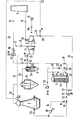
- the dust-laden top gases flow from the blast furnace 1 into the coarse dedusting 2 in the direction of arrow 2a and from there in the direction of arrow 3a into the fine dedusting 3.
- the coarse dedusting 2 is formed here by the dust bag 2b and the fine dedusting 3 by a bag filter 3b.
- the dedusted top gases can be passed on to the other consumers or discharged into the atmosphere through the muffler 10 in the direction of the arrow 15, but this does not correspond to the normal case.
- cleaned top gas is released through the valve 14 to the turbine stage 4a, which works with the further turbine stage 5a on a shaft. Both turbine stages 4a and 5a drive the shaft 11a of the generator 11. Clean gas flowing out of the turbine stage 4a is fed into the line in the direction of the arrow 15 via the control valve 16 in the direction of the arrow 17 and is treated as described.
- the turbine 4 is operated with clean gas and the turbine 5 with flue gas, so that the exhaust gas flows in the direction of the arrow 18 through the valve 19 and through the chimney 9 into the open.
- the control of the back pressure in the cowper 6 or in the blast furnace 1 takes place in parallel, starting from the pressure control valve PC via the control lines 31 for the turbine 4 or for the turbine stage 4a and via the control line 32 for the turbine 5 or the turbine stage 5a, whereby Actuators "M" act on the control valves 30 and 33, respectively.
- the septum control valve 8 is connected to this control circuit via the control line 32.
- the blast furnace 1 has its own control circuit 34 with a control element 35 for the control valve 36, which is connected upstream of the blowing wind valve 37.
Landscapes
- Engineering & Computer Science (AREA)
- Chemical & Material Sciences (AREA)
- Manufacturing & Machinery (AREA)
- Materials Engineering (AREA)
- Metallurgy (AREA)
- Organic Chemistry (AREA)
- Waste-Gas Treatment And Other Accessory Devices For Furnaces (AREA)
- Blast Furnaces (AREA)
Applications Claiming Priority (2)
| Application Number | Priority Date | Filing Date | Title |
|---|---|---|---|
| DE3435275 | 1984-09-26 | ||
| DE3435275A DE3435275C1 (de) | 1984-09-26 | 1984-09-26 | Hochofenanlage |
Publications (2)
| Publication Number | Publication Date |
|---|---|
| EP0175855A2 true EP0175855A2 (fr) | 1986-04-02 |
| EP0175855A3 EP0175855A3 (fr) | 1986-10-08 |
Family
ID=6246383
Family Applications (1)
| Application Number | Title | Priority Date | Filing Date |
|---|---|---|---|
| EP85108182A Withdrawn EP0175855A3 (fr) | 1984-09-26 | 1985-07-02 | Installation de hauts fourneaux |
Country Status (3)
| Country | Link |
|---|---|
| EP (1) | EP0175855A3 (fr) |
| DE (1) | DE3435275C1 (fr) |
| ZA (1) | ZA857382B (fr) |
Cited By (3)
| Publication number | Priority date | Publication date | Assignee | Title |
|---|---|---|---|---|
| LU91493B1 (en) * | 2008-10-31 | 2010-05-03 | Wurth Paul Sa | Method for operating a blast furnace and blast furnace installation |
| CN102352784A (zh) * | 2011-10-28 | 2012-02-15 | 西安陕鼓动力股份有限公司 | 一种炼铁高炉与烧结能量回收联合发电机组 |
| CN102575899A (zh) * | 2009-10-19 | 2012-07-11 | 保尔伍斯股份有限公司 | 从鼓风炉设备内的气体中回收能量 |
Families Citing this family (2)
| Publication number | Priority date | Publication date | Assignee | Title |
|---|---|---|---|---|
| DE4030332A1 (de) * | 1990-06-20 | 1992-01-09 | Zimmermann & Jansen Gmbh | Verfahren zur nutzung der energie des von einem hochofen stammenden gichtgases, sowie hochofenanlage zur durchfuehrung dieses verfahrens |
| CN102703628A (zh) * | 2012-06-13 | 2012-10-03 | 北京首钢国际工程技术有限公司 | 一种高炉煤气循环综合利用装置的使用方法 |
-
1984
- 1984-09-26 DE DE3435275A patent/DE3435275C1/de not_active Expired
-
1985
- 1985-07-02 EP EP85108182A patent/EP0175855A3/fr not_active Withdrawn
- 1985-09-25 ZA ZA857382A patent/ZA857382B/xx unknown
Cited By (4)
| Publication number | Priority date | Publication date | Assignee | Title |
|---|---|---|---|---|
| LU91493B1 (en) * | 2008-10-31 | 2010-05-03 | Wurth Paul Sa | Method for operating a blast furnace and blast furnace installation |
| CN102575899A (zh) * | 2009-10-19 | 2012-07-11 | 保尔伍斯股份有限公司 | 从鼓风炉设备内的气体中回收能量 |
| CN102575899B (zh) * | 2009-10-19 | 2014-12-31 | 保尔伍斯股份有限公司 | 从鼓风炉设备内的气体中回收能量 |
| CN102352784A (zh) * | 2011-10-28 | 2012-02-15 | 西安陕鼓动力股份有限公司 | 一种炼铁高炉与烧结能量回收联合发电机组 |
Also Published As
| Publication number | Publication date |
|---|---|
| ZA857382B (en) | 1986-05-28 |
| EP0175855A3 (fr) | 1986-10-08 |
| DE3435275C1 (de) | 1986-01-30 |
Similar Documents
| Publication | Publication Date | Title |
|---|---|---|
| EP1307641B1 (fr) | Procede et dispositif pour convertir de l'energie thermique en travail mecanique | |
| EP0191141B1 (fr) | Procédé et installation pour la réduction de la teneur en NOx dans le gaz brûlé lors de la combustion de combustibles fossiles dans des installations de chauffage | |
| DE4041251A1 (de) | Verfahren und anlage zur herstellung von gebranntem gut sowie zur erzeugung von elektrischer energie | |
| DE4344857A1 (de) | Verfahren und Vorrichtung zum Betreiben einer Gasturbine in einem einfachen und einem mit einer Dampfturbine kombinierten Zyklus | |
| DE3435275C1 (de) | Hochofenanlage | |
| DE3326100C2 (de) | Verfahren und Anlage zum Vermindern der Stickoxydemission in Rauchgasen von Feuerungsanlagen | |
| DE3731082C1 (en) | Method and plant for obtaining energy from solid, high-ballast fuels | |
| DE4117189A1 (de) | Verfahren zur umweltvertraeglichen erzeugung elektrischer energie in einer kombinierten gas-dampfkraftanlage und anlage zur durchfuehrung des verfahrens | |
| DE4335136A1 (de) | Verfahren und Vorrichtung zur Durchführung des Verfahrens zur Erzeugung von Gasen zum Betreiben einer Gasturbine in einem kombinierten Gas- und Dampfkraftwerk | |
| DE3136480C2 (fr) | ||
| DE3852419T2 (de) | Ofensysteme. | |
| DE1932721C3 (de) | Dampferzeuger | |
| DE3248623C1 (de) | Verfahren und Vorrichtung zum Vorwaermen der Verbrennungsmedien,insbesondere fuer die Beheizung von Winderhitzern fuer Hochoefen | |
| DE4308522A1 (de) | Lufterhitzungsanlage zur indirekten Erwärmung von Luft für Trocknungsanlagen | |
| DE4019343A1 (de) | Verfahren zur erzeugung elektrischer energie in einem kombi-kraftwerk und kombi-kraftwerk zur durchfuehruung des verfahrens | |
| DE3712977A1 (de) | Vorrichtung zum katalytischen entsticken von rauchgasen | |
| DE3516831A1 (de) | Verfahren und vorrichtung zum betreiben eines regenerativ-gasvorwaermers | |
| DE2651752A1 (de) | Verfahren und anlage zur herstellung von klinkern | |
| DE1240338B (de) | Gasturbinenanlage mit einer Druckbrennkammer fuer festen Brennstoff | |
| DE4313662C2 (de) | Verfahren zur Nutzung der im Schachtofen-Gichtgas enthaltenen Energie | |
| DE937003C (de) | Einrichtung zur Zugerzeugung fuer Martin- oder sonstige Industrieoefen mit heissen Abgasen | |
| EP0651854B1 (fr) | Procede d'exploitation d'une centrale electrique hybride | |
| CH632560A5 (en) | Gas turbine plant | |
| CH631518A5 (en) | Method and device for the heat supply of technological processes running in an enclosed space | |
| DE373575C (de) | Nach Art der Strahlgeblaese gebauter Gasbrenner zur Mischung und Wirbelung ungereinigter heisser Gase mit vorgewaermter Luft |
Legal Events
| Date | Code | Title | Description |
|---|---|---|---|
| PUAI | Public reference made under article 153(3) epc to a published international application that has entered the european phase |
Free format text: ORIGINAL CODE: 0009012 |
|
| AK | Designated contracting states |
Kind code of ref document: A2 Designated state(s): AT FR GB IT SE |
|
| PUAL | Search report despatched |
Free format text: ORIGINAL CODE: 0009013 |
|
| AK | Designated contracting states |
Kind code of ref document: A3 Designated state(s): AT FR GB IT SE |
|
| 17P | Request for examination filed |
Effective date: 19861125 |
|
| 17Q | First examination report despatched |
Effective date: 19871105 |
|
| STAA | Information on the status of an ep patent application or granted ep patent |
Free format text: STATUS: THE APPLICATION IS DEEMED TO BE WITHDRAWN |
|
| 18D | Application deemed to be withdrawn |
Effective date: 19880315 |
|
| RIN1 | Information on inventor provided before grant (corrected) |
Inventor name: EISENBARTH, MANFRED, ING. (GRAD.) |