EP0175855A2 - Blast furnace plant - Google Patents
Blast furnace plant Download PDFInfo
- Publication number
- EP0175855A2 EP0175855A2 EP85108182A EP85108182A EP0175855A2 EP 0175855 A2 EP0175855 A2 EP 0175855A2 EP 85108182 A EP85108182 A EP 85108182A EP 85108182 A EP85108182 A EP 85108182A EP 0175855 A2 EP0175855 A2 EP 0175855A2
- Authority
- EP
- European Patent Office
- Prior art keywords
- blast furnace
- cowper
- turbine
- gas turbine
- cowpers
- Prior art date
- Legal status (The legal status is an assumption and is not a legal conclusion. Google has not performed a legal analysis and makes no representation as to the accuracy of the status listed.)
- Withdrawn
Links
Images
Classifications
-
- C—CHEMISTRY; METALLURGY
- C21—METALLURGY OF IRON
- C21B—MANUFACTURE OF IRON OR STEEL
- C21B5/00—Making pig-iron in the blast furnace
- C21B5/06—Making pig-iron in the blast furnace using top gas in the blast furnace process
-
- C—CHEMISTRY; METALLURGY
- C21—METALLURGY OF IRON
- C21B—MANUFACTURE OF IRON OR STEEL
- C21B2100/00—Handling of exhaust gases produced during the manufacture of iron or steel
- C21B2100/40—Gas purification of exhaust gases to be recirculated or used in other metallurgical processes
- C21B2100/44—Removing particles, e.g. by scrubbing, dedusting
-
- C—CHEMISTRY; METALLURGY
- C21—METALLURGY OF IRON
- C21B—MANUFACTURE OF IRON OR STEEL
- C21B2100/00—Handling of exhaust gases produced during the manufacture of iron or steel
- C21B2100/60—Process control or energy utilisation in the manufacture of iron or steel
- C21B2100/62—Energy conversion other than by heat exchange, e.g. by use of exhaust gas in energy production
-
- C—CHEMISTRY; METALLURGY
- C21—METALLURGY OF IRON
- C21B—MANUFACTURE OF IRON OR STEEL
- C21B2100/00—Handling of exhaust gases produced during the manufacture of iron or steel
- C21B2100/60—Process control or energy utilisation in the manufacture of iron or steel
- C21B2100/66—Heat exchange
-
- Y—GENERAL TAGGING OF NEW TECHNOLOGICAL DEVELOPMENTS; GENERAL TAGGING OF CROSS-SECTIONAL TECHNOLOGIES SPANNING OVER SEVERAL SECTIONS OF THE IPC; TECHNICAL SUBJECTS COVERED BY FORMER USPC CROSS-REFERENCE ART COLLECTIONS [XRACs] AND DIGESTS
- Y02—TECHNOLOGIES OR APPLICATIONS FOR MITIGATION OR ADAPTATION AGAINST CLIMATE CHANGE
- Y02P—CLIMATE CHANGE MITIGATION TECHNOLOGIES IN THE PRODUCTION OR PROCESSING OF GOODS
- Y02P10/00—Technologies related to metal processing
- Y02P10/25—Process efficiency
Definitions
- the invention relates to a blast furnace system, in particular with a blast furnace operated in the counter-pressure process, with a coarse and fine dust removal downstream of the blast furnace gout and with at least one subsequent turbine stage, and also with a branch for blast furnace gas which can be combusted in one or more cowpers when admixed, whereby cold air can be fed to the cowpers by means of a cold wind blower and the hot wind generated in the cowper can be introduced into the nozzle blocks of the blast furnace.
- the dust-laden blast furnace blast furnace gas is pre-cleaned in a coarse dedusting device, a lower pressure being produced compared to the blast furnace blast furnace gas pressure and final cleaning in a fine dedusting device, a certain pressure drop also having to be accepted.
- the pressure and heat energy still contained in the clean gas is used in the downstream turbine stage, electrical energy being generated in the driven generator.
- the clean gas flowing out of the turbine is burned in a burner with the addition of air, and the hot fuel gases are fed to the cowper.
- the hot fuel gases i.e. Flue gases from the cowper are blown out into the atmosphere behind the cowper with little or no use of the thermal energy contained therein. This treatment of top gases means an energy loss in the cowper, whereby valuable energy is simply released into the atmosphere.
- the object of the invention is to make better use of the energy contained both in the blast furnace gas and in the Cowper gases.
- top gas for heating the cowper between the fine dust removal and in front of one of the turbines, ie before the expansion can be branched off and is combustible under pressure in the cowper.
- the gases in the Cowper are burned under high pressure.
- a conversion of the cowper system is not necessary, because cowper systems in counter-pressure furnaces are always designed for a correspondingly high gas pressure under wind. Combustion under high pressure is also advantageous because the blast furnace can be made smaller.
- the top gas temperature is 90 to 110 ° C, which means that the low calorific values of 600 to 650 kcal / Nm t are offset by good ignitability.
- the flue gases flowing out of the cowper can be fed to a flue gas turbine stage.
- the flue gases escaping from a Cowper under high pressure with a temperature of over 200 * C (during the Cowper heating up period) then emit energy again in a turbine.
- the heating gas generated in the cowper under higher pressure with its residual heat and the higher pressure is still used.
- Another improvement of the invention is that an independent smoke gas turbine is assigned its own generator.
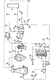
- the dust-laden top gases flow from the blast furnace 1 into the coarse dedusting 2 in the direction of arrow 2a and from there in the direction of arrow 3a into the fine dedusting 3.
- the coarse dedusting 2 is formed here by the dust bag 2b and the fine dedusting 3 by a bag filter 3b.
- the dedusted top gases can be passed on to the other consumers or discharged into the atmosphere through the muffler 10 in the direction of the arrow 15, but this does not correspond to the normal case.
- cleaned top gas is released through the valve 14 to the turbine stage 4a, which works with the further turbine stage 5a on a shaft. Both turbine stages 4a and 5a drive the shaft 11a of the generator 11. Clean gas flowing out of the turbine stage 4a is fed into the line in the direction of the arrow 15 via the control valve 16 in the direction of the arrow 17 and is treated as described.
- the turbine 4 is operated with clean gas and the turbine 5 with flue gas, so that the exhaust gas flows in the direction of the arrow 18 through the valve 19 and through the chimney 9 into the open.
- the control of the back pressure in the cowper 6 or in the blast furnace 1 takes place in parallel, starting from the pressure control valve PC via the control lines 31 for the turbine 4 or for the turbine stage 4a and via the control line 32 for the turbine 5 or the turbine stage 5a, whereby Actuators "M" act on the control valves 30 and 33, respectively.
- the septum control valve 8 is connected to this control circuit via the control line 32.
- the blast furnace 1 has its own control circuit 34 with a control element 35 for the control valve 36, which is connected upstream of the blowing wind valve 37.
Abstract
Description
Die Erfindung betrifft eine Hochofenanlage, insbesondere mit einem im Gegendruckverfahren betriebenen Hochofen, mit einer der Hochofen-Gicht nachgeordneten Grob- und Feinentstaubung und mit zumindest einer folgenden Turbinenstufe, außerdem mit einer Abzweigung für Gichtgas, das unter Beimischung in einem oder mehreren Cowpern verbrennbar ist, wobei den Cowpern mittels eines Kaltwindgebläses Kaltluft zuführbar ist und der im Cowper erzeugte Heißwind in die Düsenstöcke des Hochofens einführbar ist.The invention relates to a blast furnace system, in particular with a blast furnace operated in the counter-pressure process, with a coarse and fine dust removal downstream of the blast furnace gout and with at least one subsequent turbine stage, and also with a branch for blast furnace gas which can be combusted in one or more cowpers when admixed, whereby cold air can be fed to the cowpers by means of a cold wind blower and the hot wind generated in the cowper can be introduced into the nozzle blocks of the blast furnace.
In einer solchen Anlage wird das staubbeladene Gichtgas des Hochofens in einer Grobentstaubungseinrichtung vorgereinigt, wobei gegenüber dem Hochofen-Gichtgasdruck ein niedrigerer Druck entsteht und in einer Feinentstaubungseinrichtung endgereinigt, wobei ebenfalls ein gewisser Druckabfall hingenommen werden muß. Die im Reingas noch enthaltene Druck- und Wärmeenergie wird in der nachgeschalteten Turbinenstufe ausgenutzt, wobei im angetriebenen Generator elektrische Energie erzeugt wird.In such a system, the dust-laden blast furnace blast furnace gas is pre-cleaned in a coarse dedusting device, a lower pressure being produced compared to the blast furnace blast furnace gas pressure and final cleaning in a fine dedusting device, a certain pressure drop also having to be accepted. The pressure and heat energy still contained in the clean gas is used in the downstream turbine stage, electrical energy being generated in the driven generator.
Das aus der Turbine strömende Reingas wird unter Beimischung von Luft in einem Brenner verbrannt, und die heißen Brenngase werden dem Cowper zugeführt. Die heißen Brenngase, d.h. Rauchgase des Cowpers, werden hinter dem Cowper ohne oder unter nur geringer Nutzung der darin enthaltenen Wärmeenergie in die Atmosphäre ausgeblasen. Diese Behandlungsweise der Gichtgase bedeutet einen Energieverlust im Cowper, wobei wertvolle Energie einfach in die Atmosphäre abgegeben wird.The clean gas flowing out of the turbine is burned in a burner with the addition of air, and the hot fuel gases are fed to the cowper. The hot fuel gases, i.e. Flue gases from the cowper are blown out into the atmosphere behind the cowper with little or no use of the thermal energy contained therein. This treatment of top gases means an energy loss in the cowper, whereby valuable energy is simply released into the atmosphere.
Der Erfindung liegt die Aufgabe zugrunde, die sowohl im Hochofengichtgas als auch in den Cowper-Gasen enthaltene Energie besser auszunutzen.The object of the invention is to make better use of the energy contained both in the blast furnace gas and in the Cowper gases.
Die gestellte Aufgabe wird erfindungsgemäß dadurch gelöst, daß Gichtgas zur Beheizung der Cowper zwischen der Feinentstaubung und vor einer der Turbinen, d.h. vor der Entspannung, abzweigbar und im Cowper unter Druck verbrennbar ist. Die Verbrennung der Gase im Cowper erfolgt also unter hohem Druck. Ein Umbau der Cowper- - anlage ist nicht erforderlich, weil Cowperanlagen bei Gegendruckhochöfen in jedem Fall unter Wind für einen entsprechend hohen Gasdruck ausgelegt sind. Die Verbrennung unter hohem Druck ist außerdem vorteilhaft, weil der Gichtgasbrenner kleiner gebaut sein kann. Hinter der Feinentstaubung beträgt die Gichtgastemperatur 90 bis 110°C, wodurch den niedrigen Heizwerten von 600 bis 650 kcal/Nmt eine gute Zündfähigkeit gegenübersteht.The object is achieved according to the invention in that top gas for heating the cowper between the fine dust removal and in front of one of the turbines, ie before the expansion, can be branched off and is combustible under pressure in the cowper. The gases in the Cowper are burned under high pressure. A conversion of the cowper system is not necessary, because cowper systems in counter-pressure furnaces are always designed for a correspondingly high gas pressure under wind. Combustion under high pressure is also advantageous because the blast furnace can be made smaller. After the fine dedusting, the top gas temperature is 90 to 110 ° C, which means that the low calorific values of 600 to 650 kcal / Nm t are offset by good ignitability.
In Weiterbildung der Erfindung ist vorgesehen, daß die aus dem Cowper ausströmenden Rauchgase einer Rauchgas-Turbinenstufe zuführbar sind. Die unter hohem Druck mit einer Temperatur von über 200*C (während der Aufheizperiode der Cowper) aus einem Cowper austretenden Rauchgase geben dann noch einmal Energie in einer Turbine ab. Somit wird das im Cowper unter höherem Druck erzeugte Heizgas mit seiner Restwärme und dem höheren Druck noch verwertet.In a development of the invention it is provided that the flue gases flowing out of the cowper can be fed to a flue gas turbine stage. The flue gases escaping from a Cowper under high pressure with a temperature of over 200 * C (during the Cowper heating up period) then emit energy again in a turbine. Thus, the heating gas generated in the cowper under higher pressure with its residual heat and the higher pressure is still used.
Eine Verbesserung der Erfindung besteht ferner darin, daß einer selbständigen Rauchgasturbine ein eigener Generator zugeordnet ist.Another improvement of the invention is that an independent smoke gas turbine is assigned its own generator.
Vorteile ergeben sich außerdem dadurch, daß die Regelung des Gegendruckes im Cowper bzw. im Hochofen parallel über die vorhandenen Turbinenstufen oder über eine Gichtgasturbine und über eine Rauchgasturbine jeweils getrennt erfolgt.Advantages also result from the fact that the control of the counterpressure in the cowper or in the blast furnace takes place separately in parallel via the existing turbine stages or via a top gas turbine and a smoke gas turbine.
Ein Ausführungsbeispiel der Erfindung ist in der Zeichnung dargestellt und wird nachfolgend erläutert.An embodiment of the invention is shown in the drawing and is explained below.
Die einzige Figur der Zeichnung zeigt einen Schaltplan der Hochofenanlage.The only figure in the drawing shows a circuit diagram of the blast furnace system.
Aus dem Hochofen 1 strömen die staubbeladenen Gichtgase in die Grobentstaubung 2 in Pfeilrichtung 2a und von dort in-Pfeilrichtung 3a in die Feinentstaubung 3. Die Grobentstaubung 2 wird hierbei von dem Staubsack 2b und die Feinentstaubung 3 durch einen Schlauchfilter 3b gebildet. Die entstaubten Gichtgase können an der Abzweigung 12 je nach Stellung der Ventile 13 und 14 sowie des Septum-Ventils 8 durch den Schalldämpfer 10 in Pfeilrichtung 15 an andere Verbraucher weitergeleitet oder in die Atmosphäre abgelassen werden, was jedoch nicht dem Normalfall entspricht.The dust-laden top gases flow from the
Im Regelfall wird durch das Ventil 14 gereinigtes Gichtgas an die Turbinenstufe 4a abgegeben, die mit der weiteren Turbinenstufe 5a auf einer Welle arbeitet. Beide Turbinenstufen 4a und 5a treiben die Welle lla des Generators 11. Aus der Turbinenstufe 4a ausströmendes Reingichtgas wird über das Regelventil 16 in Pfeilrichtung 17 in die Leitung in Pfeilrichtung 15 eingespeist und wie beschrieben behandelt.As a rule, cleaned top gas is released through the
Im gezeichneten Ausführungsbeispiel werden die Turbine 4 mit Reingichtgas und die Turbine 5 mit Rauchgas betrieben, so daß das Abgas in Pfeilrichtung 18 durch das Ventil 19 und durch den Kamin 9 ins Freie strömt.In the illustrated embodiment, the turbine 4 is operated with clean gas and the turbine 5 with flue gas, so that the exhaust gas flows in the direction of the
Bei entsprechender Stellung der Ventile 13 und 14 an der Abzweigung 12 strömt Reingas in Pfeilrichtung 20 durch das geöffnete Ventil 21 in den Brenner 22 des Cowpers 6. Aus dem Kaltwindgebläse 7 des Hochofens 1 wird im Brenner 22 Luft über das Ventil 23 bzw. das Regelventil 24 während der Aufheizperiode des Cowpers 6 in Pfeilrichtung 20 zugemischt. Während der Blaswindperiode strömt bei geschlossenem Ventil 23 vom Kaltwindgebläse 7 in Pfeilrichtung 25 bei geöffnetem Ventil 26 Kaltluft durch das Mauerwerk 6a und wird erhitzt. Während der Aufheizperiode für den Cowper 6 können daher Rauchgase höheren Druckes hinter dem Cowper 6 an der Abzweigung 27 bei geöffnetem Ventil 28 in Pfeilrichtung 29 durch das Regelventil 30 in die Rauchgasturbine 5 bzw. Rauchgas-Turbinenstufe 5a gegeben werden, wobei durch eine bessere Ausnutzung der gereinigten Gichtgase, indem diese bei höherem Druck verbrannt werden, eine höhere Ausbeute an Energie in der Rauchgas-Turbinenstufe 5a bzw. in der Rauchgasturbine 5 erzielt wird.With the corresponding position of the
Die Regelung des Gegendruckes im Cowper 6 bzw. im Hochofen 1 erfolgt parallel, ausgehend von dem Drucksteuerventil PC über die Steuerleitungen 31 für die Turbine 4 bzw. für die Turbinenstufe 4a und über die Steuerleitung 32 für die Turbine 5 bzw. die Turbinenstufe 5a, wobei jeweils Stellmotoren "M" auf die Regelventile 30 bzw. 33 einwirken. Das Septum-Regelventil 8 ist an diesen Regelkreis über die Steuerleitung 32 angeschlossen.The control of the back pressure in the
Der Hochofen 1 weist einen eigenen Regelkreis 34 mit einem Kontrollorgan 35 für das Regelventil 36 auf, das dem Blaswindventil 37 vorgeschaltet ist.The
Claims (4)
dadurch gekennzeichnet,
daß Gichtgas zur Beheizung der Cowper (6) zwischen der Feinentstaubung (3) und vor einer der Turbinen (4,5), d.h. vor der Entspannung, abzweigbar und im Cowper (6) unter Druck verbrennbar ist.1. Blast furnace system, in particular with a blast furnace operated in the counterpressure process, with a coarse and fine dedusting downstream of the blast furnace gout and with at least one subsequent turbine stage, and also with a branch for blast furnace gas which can be combusted in one or more cowpers when admixed, the Cold air can be fed to Cowpern by means of a cold wind blower and the hot wind generated in the Cowper can be introduced into the nozzle blocks of the blast furnace,
characterized,
that top gas for heating the cowper (6) can be branched off between the fine dedusting (3) and in front of one of the turbines (4, 5), ie before the expansion, and combustible under pressure in the cowper (6).
daß die aus dem Cowper (6) ausströmenden Rauchgase einer Rauchgas-Turbinenstufe (5a) zuführbar sind.2. Blast furnace system according to claim 1, characterized in that
that the flue gases flowing out of the cowper (6) can be fed to a flue gas turbine stage (5a).
daß einer selbständigen Rauchgasturbine (5) ein eigener Generator (lla) zugeordnet ist.3. Blast furnace system according to claims 1 and 2, characterized in
that an independent smoke gas turbine (5) is assigned its own generator (lla).
daß die Regelung des Gegendrucks im Cowper (6) bzw. im Hochofen (1) parallel über die vorhandenen Turbinenstufen (4a,5a) oder über eine Gichtgasturbine (4) und über eine Rauchgasturbine (5) jeweils getrennt erfolgt.4. Blast furnace system according to claims 1 to 3, characterized in
that the control of the back pressure in the cowper (6) or in the blast furnace (1) is carried out separately in parallel via the existing turbine stages (4a, 5a) or via a top gas turbine (4) and a flue gas turbine (5).
Applications Claiming Priority (2)
| Application Number | Priority Date | Filing Date | Title |
|---|---|---|---|
| DE3435275 | 1984-09-26 | ||
| DE3435275A DE3435275C1 (en) | 1984-09-26 | 1984-09-26 | Blast furnace plant |
Publications (2)
| Publication Number | Publication Date |
|---|---|
| EP0175855A2 true EP0175855A2 (en) | 1986-04-02 |
| EP0175855A3 EP0175855A3 (en) | 1986-10-08 |
Family
ID=6246383
Family Applications (1)
| Application Number | Title | Priority Date | Filing Date |
|---|---|---|---|
| EP85108182A Withdrawn EP0175855A3 (en) | 1984-09-26 | 1985-07-02 | Blast furnace plant |
Country Status (3)
| Country | Link |
|---|---|
| EP (1) | EP0175855A3 (en) |
| DE (1) | DE3435275C1 (en) |
| ZA (1) | ZA857382B (en) |
Cited By (3)
| Publication number | Priority date | Publication date | Assignee | Title |
|---|---|---|---|---|
| LU91493B1 (en) * | 2008-10-31 | 2010-05-03 | Wurth Paul Sa | Method for operating a blast furnace and blast furnace installation |
| CN102352784A (en) * | 2011-10-28 | 2012-02-15 | 西安陕鼓动力股份有限公司 | Power generating set combining iron-making blast furnace and sintered energy recycling |
| CN102575899A (en) * | 2009-10-19 | 2012-07-11 | 保尔伍斯股份有限公司 | Energy recovery from gases in a blast furnace plant |
Families Citing this family (2)
| Publication number | Priority date | Publication date | Assignee | Title |
|---|---|---|---|---|
| DE4030332A1 (en) * | 1990-06-20 | 1992-01-09 | Zimmermann & Jansen Gmbh | Process and plant for energy recovery from blast furnace gas - comprises pressure recovery turbine with generator and by=pass with gas compressor, combustion chamber with fuel enrichment |
| CN102703628A (en) * | 2012-06-13 | 2012-10-03 | 北京首钢国际工程技术有限公司 | Use method for circulating comprehensive utilization device for blast furnace gas |
Citations (2)
| Publication number | Priority date | Publication date | Assignee | Title |
|---|---|---|---|---|
| JPS5267441A (en) * | 1975-12-02 | 1977-06-03 | Nippon Steel Corp | Energy recovery system of melting furnace upper gas |
| JPS57185908A (en) * | 1981-05-12 | 1982-11-16 | Kawasaki Steel Corp | Equalizing method for top pressure of blast furnace |
-
1984
- 1984-09-26 DE DE3435275A patent/DE3435275C1/en not_active Expired
-
1985
- 1985-07-02 EP EP85108182A patent/EP0175855A3/en not_active Withdrawn
- 1985-09-25 ZA ZA857382A patent/ZA857382B/en unknown
Patent Citations (2)
| Publication number | Priority date | Publication date | Assignee | Title |
|---|---|---|---|---|
| JPS5267441A (en) * | 1975-12-02 | 1977-06-03 | Nippon Steel Corp | Energy recovery system of melting furnace upper gas |
| JPS57185908A (en) * | 1981-05-12 | 1982-11-16 | Kawasaki Steel Corp | Equalizing method for top pressure of blast furnace |
Non-Patent Citations (4)
| Title |
|---|
| PATENT ABSTRACTS OF JAPAN, Band 1, Nr. 128 (M-77), 24. Oktober 1977, Seite 4314 M 77; & JP-A-52 067441 (SHIN NIPPON SEITETSU K.K.) 03.06.1977 * |
| PATENT ABSTRACTS OF JAPAN, Band 2, Nr. 31 (C-77), 27. Februar 1978, Seite 4317 C 77; JP-A-52 129 601 (HITACHI SEISAKUSHO K.K.) 31.10.1977 * |
| PATENT ABSTRACTS OF JAPAN, Band 4, Nr. 182 (C-35)[664], 16. Dezember 1980; JP-A-55 122 812 (KAWASAKI SEITETSU K.K.) 20.09.1980 * |
| PATENT ABSTRACTS OF JAPAN, Band 7, Nr. 34 (C-150)[1179], 10. Februar 1983; & JP-A-57 185 908 (KAWASAKI) 16.11.1982 * |
Cited By (4)
| Publication number | Priority date | Publication date | Assignee | Title |
|---|---|---|---|---|
| LU91493B1 (en) * | 2008-10-31 | 2010-05-03 | Wurth Paul Sa | Method for operating a blast furnace and blast furnace installation |
| CN102575899A (en) * | 2009-10-19 | 2012-07-11 | 保尔伍斯股份有限公司 | Energy recovery from gases in a blast furnace plant |
| CN102575899B (en) * | 2009-10-19 | 2014-12-31 | 保尔伍斯股份有限公司 | Energy recovery from gases in a blast furnace plant |
| CN102352784A (en) * | 2011-10-28 | 2012-02-15 | 西安陕鼓动力股份有限公司 | Power generating set combining iron-making blast furnace and sintered energy recycling |
Also Published As
| Publication number | Publication date |
|---|---|
| EP0175855A3 (en) | 1986-10-08 |
| DE3435275C1 (en) | 1986-01-30 |
| ZA857382B (en) | 1986-05-28 |
Similar Documents
| Publication | Publication Date | Title |
|---|---|---|
| EP1307641B1 (en) | Method and device for converting thermal energy into mechanical work | |
| DE2743830C2 (en) | Method for operating a combined gas-steam power plant and gas-steam power plant for carrying out the method | |
| DE4041251A1 (en) | Material firing and power generation - uses low value fuel at kiln to give hot exhaust gas which is used to generate electricity | |
| DE4344857A1 (en) | Method and device for operating a gas turbine in a simple and a combined cycle with a steam turbine | |
| DE3435275C1 (en) | Blast furnace plant | |
| DE4335136C2 (en) | Method and device for carrying out the method for generating gases for operating a gas turbine in a combined gas and steam power plant | |
| DE4117189A1 (en) | METHOD FOR THE ENVIRONMENTALLY COMPREHENSIVE GENERATION OF ELECTRICAL ENERGY IN A COMBINED GAS-VAPOR POWER PLANT AND SYSTEM FOR IMPLEMENTING THE METHOD | |
| DE1932721C3 (en) | Steam generator | |
| DE3731082C1 (en) | Method and plant for obtaining energy from solid, high-ballast fuels | |
| DE726778C (en) | Process for exhaust gas heat recovery in shaft ovens, in particular cupolas, with an air heater arranged above the top | |
| DE3326100A1 (en) | Process and plant for the reduction of nitrogen oxides emission in flue gases and furnace plants | |
| DE10032625C1 (en) | Method and device for the simultaneous generation of hot and hot gas by means of combined heat and power | |
| EP0286892A1 (en) | Catalytic nitrogen-removing device for flue gases | |
| DE4019343A1 (en) | Electrical energy prodn. in combined-cycle power plant - involves preheating of air forced into boiler, unless gas-turbine exhaust provides enough oxygen for combustion | |
| DE4308522A1 (en) | Air-heating installation for indirect heating of air for drying installations | |
| DE3831558C2 (en) | ||
| DE3516831A1 (en) | Process and apparatus for operating a regenerative gas preheater | |
| EP0394281A1 (en) | Controllable fluidized-bed combustion under pressure. | |
| EP0651854B1 (en) | Process for operating a combined power station | |
| DE2401192A1 (en) | Improvement of flue gas quality - from an incinerator and an asphalt furnace operating simultaneously | |
| DE937003C (en) | Device for generating drafts for Martin or other industrial furnaces with hot exhaust gases | |
| DE4313662C2 (en) | Process for using the energy contained in the shaft furnace blast furnace gas | |
| DE841618C (en) | Method and device for operating coking ovens, in particular vertical chamber ovens | |
| DE373575C (en) | Gas burner built like a jet blower for mixing and swirling uncleaned hot gases with preheated air | |
| DE19700768C2 (en) | Process and plant for the disposal of emission gases extracted from a coke oven battery |
Legal Events
| Date | Code | Title | Description |
|---|---|---|---|
| PUAI | Public reference made under article 153(3) epc to a published international application that has entered the european phase |
Free format text: ORIGINAL CODE: 0009012 |
|
| AK | Designated contracting states |
Kind code of ref document: A2 Designated state(s): AT FR GB IT SE |
|
| PUAL | Search report despatched |
Free format text: ORIGINAL CODE: 0009013 |
|
| AK | Designated contracting states |
Kind code of ref document: A3 Designated state(s): AT FR GB IT SE |
|
| 17P | Request for examination filed |
Effective date: 19861125 |
|
| 17Q | First examination report despatched |
Effective date: 19871105 |
|
| STAA | Information on the status of an ep patent application or granted ep patent |
Free format text: STATUS: THE APPLICATION IS DEEMED TO BE WITHDRAWN |
|
| 18D | Application deemed to be withdrawn |
Effective date: 19880315 |
|
| RIN1 | Information on inventor provided before grant (corrected) |
Inventor name: EISENBARTH, MANFRED, ING. (GRAD.) |