EP0175640A2 - Verfahren und Vorrichtung zum Überziehen durch Vakuumbeschichtung - Google Patents
Verfahren und Vorrichtung zum Überziehen durch Vakuumbeschichtung Download PDFInfo
- Publication number
- EP0175640A2 EP0175640A2 EP85730123A EP85730123A EP0175640A2 EP 0175640 A2 EP0175640 A2 EP 0175640A2 EP 85730123 A EP85730123 A EP 85730123A EP 85730123 A EP85730123 A EP 85730123A EP 0175640 A2 EP0175640 A2 EP 0175640A2
- Authority
- EP
- European Patent Office
- Prior art keywords
- vacuum
- inactive gas
- deposition plating
- chamber
- inlet
- Prior art date
- Legal status (The legal status is an assumption and is not a legal conclusion. Google has not performed a legal analysis and makes no representation as to the accuracy of the status listed.)
- Granted
Links
- 238000007747 plating Methods 0.000 title claims abstract description 65
- 238000001771 vacuum deposition Methods 0.000 title claims abstract description 60
- 238000000034 method Methods 0.000 title claims abstract description 26
- 239000007789 gas Substances 0.000 claims abstract description 102
- 238000007789 sealing Methods 0.000 claims abstract description 85
- 238000000137 annealing Methods 0.000 claims abstract description 58
- UFHFLCQGNIYNRP-UHFFFAOYSA-N Hydrogen Chemical compound [H][H] UFHFLCQGNIYNRP-UHFFFAOYSA-N 0.000 claims abstract description 55
- 239000001257 hydrogen Substances 0.000 claims abstract description 30
- 229910052739 hydrogen Inorganic materials 0.000 claims abstract description 30
- QVGXLLKOCUKJST-UHFFFAOYSA-N atomic oxygen Chemical compound [O] QVGXLLKOCUKJST-UHFFFAOYSA-N 0.000 claims abstract description 26
- 239000001301 oxygen Substances 0.000 claims abstract description 26
- 229910052760 oxygen Inorganic materials 0.000 claims abstract description 26
- 230000001105 regulatory effect Effects 0.000 claims abstract description 18
- 238000000746 purification Methods 0.000 claims abstract description 16
- 239000003921 oil Substances 0.000 claims abstract description 10
- XLYOFNOQVPJJNP-UHFFFAOYSA-N water Substances O XLYOFNOQVPJJNP-UHFFFAOYSA-N 0.000 claims abstract description 9
- 238000000151 deposition Methods 0.000 abstract description 4
- 230000008021 deposition Effects 0.000 abstract description 4
- IJGRMHOSHXDMSA-UHFFFAOYSA-N Atomic nitrogen Chemical compound N#N IJGRMHOSHXDMSA-UHFFFAOYSA-N 0.000 description 171
- 229910052757 nitrogen Inorganic materials 0.000 description 63
- 229910001873 dinitrogen Inorganic materials 0.000 description 45
- 229910000831 Steel Inorganic materials 0.000 description 42
- 239000010959 steel Substances 0.000 description 42
- 230000001070 adhesive effect Effects 0.000 description 17
- 230000002829 reductive effect Effects 0.000 description 17
- HCHKCACWOHOZIP-UHFFFAOYSA-N Zinc Chemical compound [Zn] HCHKCACWOHOZIP-UHFFFAOYSA-N 0.000 description 16
- 229910052725 zinc Inorganic materials 0.000 description 16
- 239000011701 zinc Substances 0.000 description 16
- 239000000853 adhesive Substances 0.000 description 14
- 238000004880 explosion Methods 0.000 description 9
- 229910052751 metal Inorganic materials 0.000 description 6
- 239000002184 metal Substances 0.000 description 6
- 238000005452 bending Methods 0.000 description 5
- 238000000576 coating method Methods 0.000 description 5
- 230000000694 effects Effects 0.000 description 5
- 238000011084 recovery Methods 0.000 description 5
- MYMOFIZGZYHOMD-UHFFFAOYSA-N Dioxygen Chemical compound O=O MYMOFIZGZYHOMD-UHFFFAOYSA-N 0.000 description 4
- 239000012267 brine Substances 0.000 description 4
- 229910001882 dioxygen Inorganic materials 0.000 description 4
- 230000009545 invasion Effects 0.000 description 4
- HPALAKNZSZLMCH-UHFFFAOYSA-M sodium;chloride;hydrate Chemical compound O.[Na+].[Cl-] HPALAKNZSZLMCH-UHFFFAOYSA-M 0.000 description 4
- 239000007921 spray Substances 0.000 description 4
- 239000002253 acid Substances 0.000 description 3
- 239000011248 coating agent Substances 0.000 description 3
- 238000001816 cooling Methods 0.000 description 3
- 230000003647 oxidation Effects 0.000 description 2
- 238000007254 oxidation reaction Methods 0.000 description 2
- 230000002265 prevention Effects 0.000 description 2
- 230000000717 retained effect Effects 0.000 description 2
- 238000005275 alloying Methods 0.000 description 1
- 239000003054 catalyst Substances 0.000 description 1
- 238000007796 conventional method Methods 0.000 description 1
- 238000005336 cracking Methods 0.000 description 1
- 239000010432 diamond Substances 0.000 description 1
- 230000003292 diminished effect Effects 0.000 description 1
- 238000007599 discharging Methods 0.000 description 1
- 230000001747 exhibiting effect Effects 0.000 description 1
- 239000012530 fluid Substances 0.000 description 1
- 238000000227 grinding Methods 0.000 description 1
- 238000010438 heat treatment Methods 0.000 description 1
- 150000002431 hydrogen Chemical class 0.000 description 1
- 230000001771 impaired effect Effects 0.000 description 1
- 239000000463 material Substances 0.000 description 1
- 238000002156 mixing Methods 0.000 description 1
- 239000000203 mixture Substances 0.000 description 1
- 230000001590 oxidative effect Effects 0.000 description 1
- 239000003507 refrigerant Substances 0.000 description 1
- 230000000284 resting effect Effects 0.000 description 1
- 239000002912 waste gas Substances 0.000 description 1
Images


Classifications
-
- C—CHEMISTRY; METALLURGY
- C23—COATING METALLIC MATERIAL; COATING MATERIAL WITH METALLIC MATERIAL; CHEMICAL SURFACE TREATMENT; DIFFUSION TREATMENT OF METALLIC MATERIAL; COATING BY VACUUM EVAPORATION, BY SPUTTERING, BY ION IMPLANTATION OR BY CHEMICAL VAPOUR DEPOSITION, IN GENERAL; INHIBITING CORROSION OF METALLIC MATERIAL OR INCRUSTATION IN GENERAL
- C23C—COATING METALLIC MATERIAL; COATING MATERIAL WITH METALLIC MATERIAL; SURFACE TREATMENT OF METALLIC MATERIAL BY DIFFUSION INTO THE SURFACE, BY CHEMICAL CONVERSION OR SUBSTITUTION; COATING BY VACUUM EVAPORATION, BY SPUTTERING, BY ION IMPLANTATION OR BY CHEMICAL VAPOUR DEPOSITION, IN GENERAL
- C23C14/00—Coating by vacuum evaporation, by sputtering or by ion implantation of the coating forming material
- C23C14/22—Coating by vacuum evaporation, by sputtering or by ion implantation of the coating forming material characterised by the process of coating
- C23C14/56—Apparatus specially adapted for continuous coating; Arrangements for maintaining the vacuum, e.g. vacuum locks
-
- C—CHEMISTRY; METALLURGY
- C21—METALLURGY OF IRON
- C21D—MODIFYING THE PHYSICAL STRUCTURE OF FERROUS METALS; GENERAL DEVICES FOR HEAT TREATMENT OF FERROUS OR NON-FERROUS METALS OR ALLOYS; MAKING METAL MALLEABLE, e.g. BY DECARBURISATION OR TEMPERING
- C21D9/00—Heat treatment, e.g. annealing, hardening, quenching or tempering, adapted for particular articles; Furnaces therefor
- C21D9/52—Heat treatment, e.g. annealing, hardening, quenching or tempering, adapted for particular articles; Furnaces therefor for wires; for strips ; for rods of unlimited length
- C21D9/54—Furnaces for treating strips or wire
- C21D9/56—Continuous furnaces for strip or wire
- C21D9/561—Continuous furnaces for strip or wire with a controlled atmosphere or vacuum
-
- C—CHEMISTRY; METALLURGY
- C21—METALLURGY OF IRON
- C21D—MODIFYING THE PHYSICAL STRUCTURE OF FERROUS METALS; GENERAL DEVICES FOR HEAT TREATMENT OF FERROUS OR NON-FERROUS METALS OR ALLOYS; MAKING METAL MALLEABLE, e.g. BY DECARBURISATION OR TEMPERING
- C21D9/00—Heat treatment, e.g. annealing, hardening, quenching or tempering, adapted for particular articles; Furnaces therefor
- C21D9/52—Heat treatment, e.g. annealing, hardening, quenching or tempering, adapted for particular articles; Furnaces therefor for wires; for strips ; for rods of unlimited length
- C21D9/54—Furnaces for treating strips or wire
- C21D9/56—Continuous furnaces for strip or wire
- C21D9/562—Details
- C21D9/565—Sealing arrangements
-
- C—CHEMISTRY; METALLURGY
- C23—COATING METALLIC MATERIAL; COATING MATERIAL WITH METALLIC MATERIAL; CHEMICAL SURFACE TREATMENT; DIFFUSION TREATMENT OF METALLIC MATERIAL; COATING BY VACUUM EVAPORATION, BY SPUTTERING, BY ION IMPLANTATION OR BY CHEMICAL VAPOUR DEPOSITION, IN GENERAL; INHIBITING CORROSION OF METALLIC MATERIAL OR INCRUSTATION IN GENERAL
- C23C—COATING METALLIC MATERIAL; COATING MATERIAL WITH METALLIC MATERIAL; SURFACE TREATMENT OF METALLIC MATERIAL BY DIFFUSION INTO THE SURFACE, BY CHEMICAL CONVERSION OR SUBSTITUTION; COATING BY VACUUM EVAPORATION, BY SPUTTERING, BY ION IMPLANTATION OR BY CHEMICAL VAPOUR DEPOSITION, IN GENERAL
- C23C14/00—Coating by vacuum evaporation, by sputtering or by ion implantation of the coating forming material
- C23C14/22—Coating by vacuum evaporation, by sputtering or by ion implantation of the coating forming material characterised by the process of coating
- C23C14/56—Apparatus specially adapted for continuous coating; Arrangements for maintaining the vacuum, e.g. vacuum locks
- C23C14/562—Apparatus specially adapted for continuous coating; Arrangements for maintaining the vacuum, e.g. vacuum locks for coating elongated substrates
Definitions
- the present invention relates to a method and an apparatus for vacuum deposition plating.
- means for vacuum deposition plating for the purpose of preventing the invasion of dusts and the like into a vacuum chamber from the atmosphere, it has been suggested that means for gradually reducing a pressure in the vacuum chamber from atmospheric pressure is provided so as to stepwise form vacuum conditions and that a chamber containing an inactive gas atmosphere is disposed between an annealing furnace and the vacuum chamber (Japanese Patent Publication No. 6576/1969 and Japanese Patent Provisional Publication No. 85742/1978).
- an adhesive strength of a plated matallic coating on a strip steel must be such that peeling, cracking and powdering do not occur, even if subjected to rigorous works such as 180° ot-bending work, reverse rethrottle bending work and the like.
- a nitrogen replacement chamber is disposed between the anealing furnace and the vacuum chamber, and a nitrogen gas (N 2 gas) is introduced into the nitrogen replacement chamber to replace the hydrogen gas with the nitrogen gas therein, whereby the N 2 gas is discharged by vacuum and thus the danger of the explosion can be avoided.
- N 2 gas is discharged out of the system in vain, which fact leads to the increase in material costs disadvantageously.
- an object of the present invention is to provide a vacuum deposition plating method capable of solving the above-mentioned problems without impairing functions inherent in an annealing furnace and a vacuum chamber and a vacuum deposition plating apparatus for performing the new method.
- the present invention is concerned with a method for vacuum deposition plating which comprises using a vacuum deposition plating apparatus having an inlet-side vacuum sealing device provided in front of a vacuum deposition plating chamber, an inlet-side inactive gas replacement chamber provided between the inlet-side vacuum sealing device and an annealing furnace, an outlet-side vacuum sealing device provided in the rear of the vacuum deposition plating chamber, an outlet-side inactive gas replacement chamber provided between the outlet-side vacuum sealing device and the atmosphere, and an inactive gas circulating/purifying device for circulating an inactive gas from vacuum chambers of both the vacuum sealing devices to atmospheric pressure chambers of both the vacuum sealing devices and for removing water, oil and oxygen from the inactive gas, said method for vacuum deposition plating being characterized by regulating concentrations of oxygen and hydrogen in the inactive gas after the purification to 60 ppm or less and 0.2 to 2.0%, respectively, and regulating a dew point of the inactive gas to -50°C or less.
- the present invention is concerned with a method for vacuum deposition plating which comprises using a vacuum deposition plating apparatus having an inlet-side vacuum sealing device provided in front of a vacuum deposition plating chamber, an inlet-side inactive gas replacement chamber provided between the inlet-side vacuum sealing device and an annealing furnace, an outlet-side vacuum sealing device provided in the rear of the vacuum deposition plating chamber, an outlet-side inactive gas replacement chamber provided between the outlet-side vacuum sealing device and the atmosphere, and an inactive gas circulating/purifying device for circulating an inactive gas from vacuum chambers of both the vacuum sealing devices to atmospheric pressure chambers of both the vacuum sealing devices and for removing water, oil and oxygen from the inactive gas, the aforesaid method for vacuum deposition plating being characterized by regulating a pressure P 1 in the annealing furnace to atmospheric pressure or more, a pressure P 2 in the inlet-side inactive gas replacement chamber to atmospheric pressure or more, a pressure P 3 in the outlet-side inactive gas replacement chamber to atmospheric pressure or more,
- the present invention is concerned with a vacuum deposition plating apparatus characterized by comprising an inlet-side vacuum sealing device provided in front of a vacuum deposition plating chamber; an inlet-side inactive gas replacement chamber provided between the inlet-side vacuum sealing device and an annealing furnace; an outlet-side vacuum sealing device provided in the rear of the vacuum deposition plating chamber; an outlet-side inactive gas replacement chamber provided between the outlet-side vacuum sealing device and the atmosphere; an inactive gas circulating/purifying device for circulating an inactive gas from vacuum chambers of both the vacuum sealing devices to atmospheric pressure chambers of both the vacuum sealing devices and for removing water, oil and oxygen from the inactive gas; a pressure gauge provided on the annealing furnace; a pressure gauge, a control valve, an automatic valve, a hydrogen concentration detector and a discharge valve provided on the inlet-side inactive gas replacement chamber; a pressure gauge and an automatic valve provided on the outlet-side inactive gas replacement chamber; and an automatic valve connecting to an inactive gas tank for emergency provided on the atmospheric pressure chambers
- the nitrogen replacement chamber is provided between the annealing furnace and the vacuum sealing device, and the sealing rolls are provided between the annealing furnace and the nitrogen replacement chamber and between the nitrogen replacement chamber and the vacuum sealing device. These sealing rolls are manufactured like sealing rolls used in the vacuum sealing device.
- a pressure in the annealing furnace is regulated so as to be equal to or a little higher than that in the nitrogen replacement chamber. For example, when the pressure in the furnace is equal to that in the chamber, the hydrogen gas does not flow from the annealing furnace to the nitrogen replacement chamber and thus there is no danger of increasing an amount of hydrogen in the nitrogen replacement chamber and bringing about an explosion.
- the above-mentioned sealing rolls used in the present invention are constituted so that a space area between each pair of rolls through which the gas passes may be extremely small. That is to say, the sealing rolls have a gas tight structure, and thus a flow rate of the gas is low even under chock conditions (when a pressure ratio of a low pressure/a high pressure is 0.52 or less). Therefore, when the pressure in the annealing furnace is equal to that in the nitrogen replacement chamber, the gas does not flow anywhere. Even when the pressure in the annealing furnace is slightly higher than that in the nitrogen replacement chamber and a differential pressure occurs therebetween, an amount of the leaked gas is so small as to be negligible.
- the hydrogen gas diffuses into the nitrogen replacement chamber through a narrow space between the rolls. Similarly, the nitrogen gas also moves into the annealing furnace diffusely.
- the strip steel which has been annealed and reduced in the annealing furnace has an active surface for enabling the vacuum deposition plating.
- the hydrogen gas is allowed to diffuse into the nitrogen replacement chamber.
- the pressure in the annealing furnace is regulated to a little higher level than that in the nitrogen replacement chamber so that a small amount of the hydrogen gas may be allowed to leak into the nitrogen replacement chamber, whereby an amount of hydrogen in the nitrogen replacement chamber is adjusted to 2.0% or less, preferably 0.2 to 2.0%, in order to prepare a weakly reductive atmosphere.
- a concentration of oxygen in the purified inactive gas and its dew point are controlled to 60 ppm or less and -50°C or less, respectively.
- the pressure P 1 in the annealing furnace is regulated to atmospheric pressure or more.
- the reason for such a regulation is that the atmosphere gas in the annealing furnace comprises 5 to 75% of hydrogen and 95 to 25% of nitrogen and is in danger of an explosion when oxygen (air) invades the annealing furnace, and thus it is required to prevent the atmosphere from invading the annealing furnace.
- the pressure P 1 is adjusted to a level of atmospheric pressure + 5 mmAq.
- NOF non- oxidizing furnace
- a pressure resulting from a burned waste gas can be obtained. That is to say, since the atmosphere gas is always fed to the annealing furnace, the pressure in the whole annealing furnace can be maintained at a level of atmospheric pressure + 5 mmAq.
- a pressure P 2 in the inlet-side inactive gas replacement chamber is regulated to atmospheric pressure or more in order to inhibit the invasion of air, and in view of the pressure PI in the annealing furnace being atmospheric pressure + 5 mmAq, the pressure P 2 in the inlet-side inactive gas replacement chamber preferably is atmospheric pressure + 5 to 4 mmAq.
- the flow of the atmosphere gas containing 5 to 75% of hydrogen and 95 to 25% of nitrogen into the replacement chamber is accomplished, so that a concentration of hydrogen in the atmosphere gas in the replacement chamber is adjusted to 2.0%or less, preferably 0.2 to 2.0%, and so that a concentration of nitrogen therein is controlled within the range of 99.8 to 98%.
- the pressure P 3 in the outlet-side inactive gas replacement chamber is regulated to atmospheric pressure, preferably atmospheric pressure + 5 mmAq.
- atmospheric pressure preferably atmospheric pressure + 5 mmAq.
- the relation between the pressures P 1 and P 2 is regulated to P 1 - P 2 ⁇ 0 mmAq.
- P 1 and P 2 each are atmospheric pressure or more
- P 1 ' P 2' Preferably, P 1 is the atmospheric pressure + 5 mmAq.
- control means works to open the discharge valve so as to maintain P 1 - P 2 ⁇ 0.
- H 2 hydrogen gas
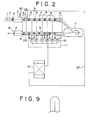
- it is delivered through a vacuum sealing device 5 comprising a plurality of sealing rolls 4, and at this time, it passes through a high-vacuum atmosphere in the vacuum sealing device 5 in which a pressure is gradually diminished.
- the strip steel 1 is then forwarded, via a turn down roll 6, to a vacuum deposition chamber 7, where a molten metal (not shown) evaporates and the strip steel 1 is plated with the molten metal.
- the strip steel 1 is guided into the atmosphere through the vacuum sealing device 5 again and a nitrogen replacement chamber 8.
- the above-mentioned vacuum sealing device 5 has a plurality of sealing rolls 4 and vacuum chambers 9, and the respective vacuum chambers 9 are evacuated by a plurality of vacuum pumps 10 in a vacuum evacuation system 11.
- the nitrogen replacement chamber 3, the vacuum sealing device 5, the vacuum deposition chamber 7 and the nitrogen replacement chamber 8 are filled with a nitrogen gas.
- the nitrogen gas which has been discharged from the vacuum chambers 9 by virtue of vacuum is delivered from the vacuum evacuation system 11 to a nitrogen purification system 12.
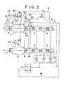
- the nitrogen gas introduced into the nitrogen purification system 12 is then forwarded, via a buffer tank 13 and a Roots-blower 14, to a heat exchanger 15, in which it is cooled.
- a cooling device 17 comprising a refrigerator and containing a refrigerant, the nitrogen gas is further cooled to remove moisture therefrom.
- an oil remover 18 an oil is removed from the nitrogen gas, and the latter is then heated during passing through a heat exchanger 15 again and is delivered to an acid removing tower 19 via a mixer 21.
- a hydrogen gas is introduced into the mixer 21 and is mixed with the nitrogen gas therein.
- the removal of oxygen is carried out by the function of a catalyst present in the acid removing tower 19, and the oxygen-free nitrogen gas is then delivered to a drier 22, in which moisture is further removed therefrom, so that a dew point of the nitrogen gas is lowered, thereby obtaining the purified nitrogen gas.
- the two driers may be provided'if necessary, and in this case, one drier may be operated to lower the dew point of the nitrogen gas, and the other drier may be at rest and during this rest, moisture in the other drier may be eliminated therefrom for its recovery.
- a part of a gas discharged from the acid removing tower 19 may be used as a gas for the recovery.
- the nitrogen gas containing moisture is delivered from the drier 22 to a cooling device 25, in which moisture is removed therefrom. Further, the nitrogen gas is forcedly delivered by a Roots-blower 23 to a heater 24, in which it is dried, and it is further forwarded to the drier 22 in which moisture is removed therefrom.
- the fluid is continuously circulated through a recovery circulation passage of the respective equipments for the recovery in order to recover the drier now resting.
- the recovered drier can be exchanged for the drier now operating, which fact permits a continuous operation of the nitrogen purification system.
- the water collected in the cooling device 25 is discharged from the system through a drain (having a check valve) 32.
- the nitrogen gas 27 which has been purified in the nitrogen purification system 12 is delivered to an atmospheric pressure chamber 26 in the vacuum sealing device, and it is caused to flow through the respective stepwise sections in the vacuum sealing device 5 and is then discharged through the vacuum evacuation system 11 again. That is to say, the nitrogen gas 27 is circulated through a closed cycle.
- the water content, the oxygen concentration and the temperature of the nitrogen gas are automatically controlled by a moisture meter 28, an oxygen meter 29 and a thermometer 30, respectively, so that the oxygen concentration and the dew point are regulated to about 10 ppm or less and about -50°C or less, respectively.
- the purified nitrogen gas is brought into contact with the strip steel 1 during passing through the vacuum sealing device 5.
- the strip steel 1 is guided to the vacuum sealing device 5 comprising a plurality of the sealing rolls 4, a plurality of the vacuum chambers 9 and an atmospheric pressure chamber 26, and is then delivered to the vacuum deposition chamber 7 via the turn down roll 6.
- the vacuum deposition chamber 7 the strip steel 1 is plated with the molten metal (not shown).
- the strip steel 1 is then delivered through the vacuum sealing device 5 again, and is guided from the deposition device system to the atmosphere through the outlet-side nitrogen replacement chamber 8.
- the nitrogen gas discharged from the respective vacuum chambers 9 by the vacuum evacuation system 11 comprising a plurality of vacuum pumps 10 is then delivered to the nitrogen purification system 12, in which moisture, an oxygen gas and an oil are removed from the discharged nitrogen gas.
- the hydrogen gas is introduced into the system so that a concentration of hydrogen may be 2.0% or less, preferably within the range of 0.2 to 2.0%.
- the thus obtained reductive atmosphere gas is fed to the atmospheric pressure chamber 26 in the vacuum sealing device 5 again.
- a circulating cycle comprising the vacuum chamber 9, the nitrogen purification system 12, the atmospheric pressure chamber 26 and the vacuum chambers 9 is established for the nitrogen gas.
- a pressure P 1 in the annealing furnace 2 is detected by a pressure gauge 33, and a pressure P 2 in the nitrogen replacement chamber 3 is detected by a pressure gauge 34.
- the nitrogen gas with which the vacuum sealing device 5 and the vacuum deposition chamber (not shown) have been filled at an early stage is discharged therefrom by the vacuum evacuation system 11 comprising the vacuum pumps 10. And it is afterward purified in the nitrogen purification system 12, is returned to the atmospheric pressure chamber 26 in the vacuum sealing device 5 through a pipe 45, and is discharged therefrom via the vacuum chambers 9 again.
- the pressure P 2 in the nitrogen replacement chamber 3 is controlled so as to be atmospheric pressure or more, preferably atmospheric pressure + 4 to 5 mmAq. This control is made by operating a control valve 36 in accordance with a signal from the pressure gauge 34 and feeding the nitrogen gas 37 to the nitrogen replacement chamber 3.
- a hydrogen concentration detector 39 operates when the hydrogen concentration exceeds 2.0%, and an automatic valve 38 is brought into action in turn, whereby the nitrogen gas 37 is introduced into the nitrogen replacement chamber 3 to dilute the concentration of hydrogen.
- the automatic valve 38 is closed.
- a discharge valve 46 allows the excessive atmosphere gas in the nitrogen replacement chamber 3 to be discharged therefrom into the atmosphere.
- a pressure P 3 in the nitrogen replacement chamber 8 provided on the outlet side of the vacuum sealing device 5 is detected by a pressure gauge 42, and its control is made by feeding the nitrogen gas 17 to the nitrogen replacement chamber 8 through the automatic valve 43 so that the pressure P 3 may be at a level of atmospheric pressure, preferably atmospheric pressure + 5 mmAq.
- an automatic valve 40 is opened in order to feed the nitrogen gas from an emergency nitrogen tank 41 to the vacuum sealing device 5 and to thereby restore the pressure in the atmospheric pressure chamber 26 to the atmospheric pressure.
- This constitution prevents the concentrated hydrogen gas from flowing from the annealing furnace 2 into the circulating system, and also prevents the oxygen gas from flowing from the atmosphere into the outlet-side nitrogen replacement chamber 8 and the oxygen gas from invading the circulating system. After all, the explosion of the whole apparatus is obviated beforehand and security is thus assured.
- the security of the safe nitrogen replacement chambers 3 and 8 and the adjustment of the pressures therein to the desired levels can be accomplished only by providing the gas tight sealing rolls 4.
- these sealing rolls 4 known ones can be used.
- Vacuum steps and vacuum degree in vacuum sealing device 200 Torr/70 Torr/10 Torr/1 Torr/0.1 Torr/0.01 Torr Vacuum evacuation volume 780 Nm 3 /h
- Component properties of gas at inlet of nitrogen purification system :
- a strip steel was caused to pass through a weakly reductive atmosphere containing a mixture of a purified nitrogen gas and a hydrogen gas in a vacuum sealing chamber, and a vacuum deposition plating of zinc was carried out.
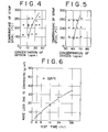
- Fig. 4 indicates that with regard to adhesive strengths of the plated zinc coatings on the strip steels in the case that the vacuum deposition plating was given at the respective strip steel temperatures by mixing no hydrogen gas with the circulating nitrogen gas and by changing the concentrations of oxygen, their good results were obtained at strip steel temperatures of 160 to 250°C and at the oxygen concentrations of about 10 ppm or less.
- a strip steel was plated with zinc under the following conditions in accordance with a vacuum deposition plating method.
- component properties of the circulating purified gas were as follows:
- Vacuum deposition plating was carried out while the surface of the strip steel was kept active in a vacuum sealing chamber.
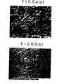
- Fig. 6 shows the results of brine spray anti-corrosive tests of the vacuum zinc plated coatings at a strip steel temperature of 255°C
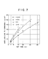
- Fig. 7 compares the results of brine spray anti-corrosive tests of products zinc-plated by the vacuum deposition plating method at a strip steel temperature of 255°C in Fig. 6 and products zinc-plated by other plating methods. It is apparent from Fig. 7 that the products obtained by the deposition plating method were better in anticorrosion than the others.
- the abbreviation "ZVD" (circular symbol) represents the products vacuum-plated according to the present invention (the same as the products represented by the triangular symbol in Fig. 6)
- “EG” cross symbol
- HDG triangular symbol
- HDGA diamond symbol
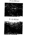
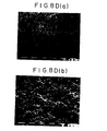
- Fig. 8 shows photomicrographs of the products zinc-plated by the vacuum deposition plating method at the strip steel temperature of 255°C in Fig. 6 and the products zinc-plated in accordance with the other methods.
- Fig. 8 (C) the HDG product 65 g/m 2 )
- Fig. 8 shows photomicrographs of the products zinc-plated by the vacuum deposition plating method at the strip steel temperature of 255°C in Fig. 6 and the products zinc-plated in accordance with the other methods.
- the vacuum deposition plating can be carried out in the deposition chamber while the activated strip steel surface state provided in the annealing furnace can be maintained, and thus the plated metal can have a good adhesive strength.
Landscapes
- Chemical & Material Sciences (AREA)
- Engineering & Computer Science (AREA)
- Materials Engineering (AREA)
- Mechanical Engineering (AREA)
- Metallurgy (AREA)
- Organic Chemistry (AREA)
- Physics & Mathematics (AREA)
- Thermal Sciences (AREA)
- Crystallography & Structural Chemistry (AREA)
- Chemical Kinetics & Catalysis (AREA)
- Physical Vapour Deposition (AREA)
- Heat Treatment Of Strip Materials And Filament Materials (AREA)
Applications Claiming Priority (4)
| Application Number | Priority Date | Filing Date | Title |
|---|---|---|---|
| JP192573/84 | 1984-09-17 | ||
| JP59192574A JPS6173880A (ja) | 1984-09-17 | 1984-09-17 | 真空蒸着メツキ方法及び真空蒸着メツキ装置 |
| JP192574/84 | 1984-09-17 | ||
| JP59192573A JPS6173879A (ja) | 1984-09-17 | 1984-09-17 | 真空蒸着メツキ方法 |
Publications (3)
| Publication Number | Publication Date |
|---|---|
| EP0175640A2 true EP0175640A2 (de) | 1986-03-26 |
| EP0175640A3 EP0175640A3 (en) | 1987-12-02 |
| EP0175640B1 EP0175640B1 (de) | 1990-05-30 |
Family
ID=26507400
Family Applications (1)
| Application Number | Title | Priority Date | Filing Date |
|---|---|---|---|
| EP85730123A Expired - Lifetime EP0175640B1 (de) | 1984-09-17 | 1985-09-16 | Verfahren und Vorrichtung zum Überziehen durch Vakuumbeschichtung |
Country Status (6)
| Country | Link |
|---|---|
| US (2) | US4676999A (de) |
| EP (1) | EP0175640B1 (de) |
| KR (1) | KR890004618B1 (de) |
| AU (1) | AU585531B2 (de) |
| CA (1) | CA1239060A (de) |
| DE (1) | DE3577997D1 (de) |
Cited By (6)
| Publication number | Priority date | Publication date | Assignee | Title |
|---|---|---|---|---|
| FR2628752A1 (fr) * | 1988-03-16 | 1989-09-22 | Air Liquide | Procede et dispositif de traitement de recuit de bandes metalliques en four vertical |
| FR2628753A1 (fr) * | 1988-03-16 | 1989-09-22 | Air Liquide | Procede et dispositif de traitement de recuit d'articles metalliques en four horizontal |
| US4966632A (en) * | 1988-03-16 | 1990-10-30 | L'air Liquide, Societe Anonyme Pour L'etude Et L'exploitation Des Procedes Georges Claude | Process for the annealing treatment of metal strips |
| EP0730045A3 (de) * | 1995-02-28 | 1997-09-17 | Nisshin Steel Co Ltd | Stahlblech mit korrosionsbeständiger Zweikomponentenschicht aus Zn-Mg sowie Verfahren zu dessen Herstellung |
| US6217633B1 (en) | 1997-12-01 | 2001-04-17 | Nippon Sanso Corporation | Method and apparatus for recovering rare gas |
| US20150013846A1 (en) * | 2012-03-08 | 2015-01-15 | Baoshan Iron & Steel Co., Ltd. | Method for Producing Silicon Steel Normalizing Substrate |
Families Citing this family (15)
| Publication number | Priority date | Publication date | Assignee | Title |
|---|---|---|---|---|
| JPH0621348B2 (ja) * | 1986-07-22 | 1994-03-23 | 日新製鋼株式会社 | 合金化亜鉛メツキ鋼板とその製造法 |
| EP0337329A3 (de) * | 1988-04-12 | 1990-11-22 | Siemens Aktiengesellschaft | Verfahren zur Herstellung dünner Metallfilme durch Aufdampfen |
| JPH0762239B2 (ja) * | 1990-09-28 | 1995-07-05 | 三菱重工業株式会社 | 真空蒸着装置 |
| US5487783A (en) * | 1994-04-14 | 1996-01-30 | International Business Machines Corporation | Method and apparatus for preventing rupture and contamination of an ultra-clean APCVD reactor during shutdown |
| US5826773A (en) * | 1997-01-31 | 1998-10-27 | Straemke; Siegfried | Rope material transfer structure |
| US6105435A (en) | 1997-10-24 | 2000-08-22 | Cypress Semiconductor Corp. | Circuit and apparatus for verifying a chamber seal, and method of depositing a material onto a substrate using the same |
| US20070137653A1 (en) * | 2000-03-13 | 2007-06-21 | Wood Thomas J | Ventilation interface for sleep apnea therapy |
| JP3543949B2 (ja) * | 1999-11-09 | 2004-07-21 | 東京エレクトロン株式会社 | 熱処理装置 |
| US7518880B1 (en) | 2006-02-08 | 2009-04-14 | Bi-Link | Shielding arrangement for electronic device |
| US8281734B2 (en) * | 2006-05-02 | 2012-10-09 | Dow Corning Ireland, Ltd. | Web sealing device |
| JP2009535514A (ja) * | 2006-05-02 | 2009-10-01 | ダウ・コーニング・アイルランド・リミテッド | 流体交換システム |
| US20100257732A1 (en) * | 2009-04-14 | 2010-10-14 | Ziberna Frank J | Shielding Arrangement for Electronic Device |
| KR101656283B1 (ko) * | 2012-04-06 | 2016-09-09 | 제이에프이 스틸 가부시키가이샤 | 연속식 용융 아연 도금 설비 |
| DE102020126101A1 (de) | 2020-10-06 | 2022-04-07 | Thyssenkrupp Steel Europe Ag | Beschichtungsvorrichtung zum Ablagern eines Beschichtungsmaterials auf einem Substrat |
| US20230272526A1 (en) * | 2021-11-11 | 2023-08-31 | Soliyarn, Llc | System, method and composition for producing liquid repellant materials |
Family Cites Families (15)
| Publication number | Priority date | Publication date | Assignee | Title |
|---|---|---|---|---|
| US24852A (en) * | 1859-07-26 | Twyer | ||
| US2382432A (en) * | 1940-08-02 | 1945-08-14 | Crown Cork & Seal Co | Method and apparatus for depositing vaporized metal coatings |
| US2622041A (en) * | 1948-08-03 | 1952-12-16 | Nat Res Corp | Deposition of metal on a nonmetallic support |
| US2580976A (en) * | 1949-09-07 | 1952-01-01 | Ohio Commw Eng Co | Apparatus for plating metal strips |
| USRE24852E (en) | 1952-07-07 | 1960-08-09 | Method of coating interior of tubing | |
| US2972330A (en) * | 1956-02-15 | 1961-02-21 | Nat Steel Corp | Vacuum seal for coating apparatus |
| BE571259A (de) * | 1957-09-16 | |||
| US2975753A (en) * | 1958-11-18 | 1961-03-21 | Nat Res Corp | Vacuum coating apparatus |
| US3325620A (en) * | 1963-02-07 | 1967-06-13 | Temescal Metallurgical Corp | Furnace |
| DE1959713C2 (de) * | 1969-11-28 | 1975-11-27 | Fa. J. Aichelin, 7015 Korntal | Verfahren zur reinigung der schutzgasatmosphaere eines industrieofens und zur durchfuehrung dieses verfahrens eingerichteter durchlaufindustrieofen |
| GB1393610A (en) * | 1971-06-15 | 1975-05-07 | Siemens Ag | Electrical conductors comprising both superconductive material and normally conductive material |
| BE795116A (fr) * | 1972-02-08 | 1973-05-29 | Cockerill | Procede d'alimentation de bain d'evaporation |
| LU69164A1 (de) * | 1974-01-15 | 1974-04-08 | ||
| US4096823A (en) * | 1977-01-27 | 1978-06-27 | University Of Virginia | Apparatus for metallization of fibers |
| DE2747061A1 (de) * | 1977-10-20 | 1979-04-26 | Leybold Heraeus Gmbh & Co Kg | Verfahren und vorrichtung zum beschichten von baendern in vakuumanlagen mit schleuseneinrichtungen |
-
1985
- 1985-09-11 US US06/774,818 patent/US4676999A/en not_active Expired - Lifetime
- 1985-09-11 AU AU47373/85A patent/AU585531B2/en not_active Ceased
- 1985-09-16 EP EP85730123A patent/EP0175640B1/de not_active Expired - Lifetime
- 1985-09-16 KR KR1019850006764A patent/KR890004618B1/ko not_active Expired
- 1985-09-16 CA CA000490764A patent/CA1239060A/en not_active Expired
- 1985-09-16 DE DE8585730123T patent/DE3577997D1/de not_active Expired - Lifetime
-
1986
- 1986-04-24 US US06/855,793 patent/US4674443A/en not_active Expired - Lifetime
Cited By (9)
| Publication number | Priority date | Publication date | Assignee | Title |
|---|---|---|---|---|
| FR2628752A1 (fr) * | 1988-03-16 | 1989-09-22 | Air Liquide | Procede et dispositif de traitement de recuit de bandes metalliques en four vertical |
| FR2628753A1 (fr) * | 1988-03-16 | 1989-09-22 | Air Liquide | Procede et dispositif de traitement de recuit d'articles metalliques en four horizontal |
| US4966632A (en) * | 1988-03-16 | 1990-10-30 | L'air Liquide, Societe Anonyme Pour L'etude Et L'exploitation Des Procedes Georges Claude | Process for the annealing treatment of metal strips |
| BE1007266A3 (fr) * | 1988-03-16 | 1995-05-09 | Air Liquide | Procede et dispositif de traitement de recuit de bandes metalliques. |
| EP0730045A3 (de) * | 1995-02-28 | 1997-09-17 | Nisshin Steel Co Ltd | Stahlblech mit korrosionsbeständiger Zweikomponentenschicht aus Zn-Mg sowie Verfahren zu dessen Herstellung |
| US5747111A (en) * | 1995-02-28 | 1998-05-05 | Nisshin Steel Co., Ltd. | Steel sheet coated with Zn-Mg binary coating layer excellent in corrosion resistance and manufacturing method thereof |
| US6217633B1 (en) | 1997-12-01 | 2001-04-17 | Nippon Sanso Corporation | Method and apparatus for recovering rare gas |
| US20150013846A1 (en) * | 2012-03-08 | 2015-01-15 | Baoshan Iron & Steel Co., Ltd. | Method for Producing Silicon Steel Normalizing Substrate |
| US9738946B2 (en) * | 2012-03-08 | 2017-08-22 | Baoshan Iron & Steel, Co., Ltd. | Method for producing silicon steel normalizing substrate |
Also Published As
| Publication number | Publication date |
|---|---|
| US4676999A (en) | 1987-06-30 |
| AU585531B2 (en) | 1989-06-22 |
| KR860002592A (ko) | 1986-04-28 |
| EP0175640A3 (en) | 1987-12-02 |
| DE3577997D1 (de) | 1990-07-05 |
| US4674443A (en) | 1987-06-23 |
| CA1239060A (en) | 1988-07-12 |
| KR890004618B1 (ko) | 1989-11-20 |
| AU4737385A (en) | 1986-03-27 |
| EP0175640B1 (de) | 1990-05-30 |
Similar Documents
| Publication | Publication Date | Title |
|---|---|---|
| EP0175640B1 (de) | Verfahren und Vorrichtung zum Überziehen durch Vakuumbeschichtung | |
| KR101011897B1 (ko) | Si를 함유하는 강판의 연속 어닐링 용융 도금 방법 및연속 어닐링 용융 도금 장치 | |
| RU2426815C2 (ru) | Способ непрерывного отжига и подготовки полосы из высокопрочной стали для ее цинкования путем окунания с подогревом | |
| EP2806043B1 (de) | Anlage zum dauerglühen und dauerglühverfahren für bandstahl | |
| JPH0617501B2 (ja) | 金属熱処理方法 | |
| EP0356783A2 (de) | Verfahren zur kontinuierlichen Heisstauchbeschichtung eines Stahlbandes mit Aluminium | |
| KR910004610B1 (ko) | 용융도금에 의한 비 시효 아연도금 강철 스트립의 제조방법 | |
| CN105074021B (zh) | 连续熔融镀锌装置 | |
| US4675214A (en) | Hot dip aluminum coated chromium alloy steel | |
| US4883723A (en) | Hot dip aluminum coated chromium alloy steel | |
| US6228321B1 (en) | Box annealing furnace method for annealing metal sheet using the same and annealed metal sheet | |
| EP0980913B1 (de) | Verfahren und Vorrichtung zur Erzeugung einer Atmosphere für die Wärmebehandlung von Werkstoffen | |
| US4052235A (en) | Method of preventing oxidation during water quenching of steel strip | |
| US5207839A (en) | Processes for the production of a controlled atmosphere for heat treatment of metals | |
| US2231009A (en) | Heat treating process | |
| US4800135A (en) | Hot dip aluminum coated chromium alloy steel | |
| JPS61213324A (ja) | 鉄系積層製品の連続焼鈍・ブルーイング装置 | |
| US3615926A (en) | Quench system | |
| US5066549A (en) | Hot dip aluminum coated chromium alloy steel | |
| DE3109499C2 (de) | ||
| JP4797601B2 (ja) | 高強度溶融亜鉛めっき鋼板の製造方法および溶融亜鉛めっき鋼板の製造設備 | |
| US5167735A (en) | Process for the annealing of steel annealing material | |
| JPH032232B2 (de) | ||
| CA1259050A (en) | Method and apparatus for the continuous annealing of steel strips | |
| JP2820359B2 (ja) | 連続焼鈍炉の炉内雰囲気調整方法 |
Legal Events
| Date | Code | Title | Description |
|---|---|---|---|
| PUAI | Public reference made under article 153(3) epc to a published international application that has entered the european phase |
Free format text: ORIGINAL CODE: 0009012 |
|
| AK | Designated contracting states |
Kind code of ref document: A2 Designated state(s): BE DE FR GB |
|
| 17P | Request for examination filed |
Effective date: 19860318 |
|
| PUAL | Search report despatched |
Free format text: ORIGINAL CODE: 0009013 |
|
| AK | Designated contracting states |
Kind code of ref document: A3 Designated state(s): BE DE FR GB |
|
| 17Q | First examination report despatched |
Effective date: 19881205 |
|
| GRAA | (expected) grant |
Free format text: ORIGINAL CODE: 0009210 |
|
| AK | Designated contracting states |
Kind code of ref document: B1 Designated state(s): BE DE FR GB |
|
| PG25 | Lapsed in a contracting state [announced via postgrant information from national office to epo] |
Ref country code: BE Effective date: 19900530 |
|
| ET | Fr: translation filed | ||
| REF | Corresponds to: |
Ref document number: 3577997 Country of ref document: DE Date of ref document: 19900705 |
|
| PLBE | No opposition filed within time limit |
Free format text: ORIGINAL CODE: 0009261 |
|
| STAA | Information on the status of an ep patent application or granted ep patent |
Free format text: STATUS: NO OPPOSITION FILED WITHIN TIME LIMIT |
|
| 26N | No opposition filed | ||
| PGFP | Annual fee paid to national office [announced via postgrant information from national office to epo] |
Ref country code: GB Payment date: 19960909 Year of fee payment: 12 |
|
| PGFP | Annual fee paid to national office [announced via postgrant information from national office to epo] |
Ref country code: FR Payment date: 19960910 Year of fee payment: 12 |
|
| PG25 | Lapsed in a contracting state [announced via postgrant information from national office to epo] |
Ref country code: GB Free format text: LAPSE BECAUSE OF NON-PAYMENT OF DUE FEES Effective date: 19970916 |
|
| PGFP | Annual fee paid to national office [announced via postgrant information from national office to epo] |
Ref country code: DE Payment date: 19970919 Year of fee payment: 13 |
|
| PG25 | Lapsed in a contracting state [announced via postgrant information from national office to epo] |
Ref country code: FR Free format text: THE PATENT HAS BEEN ANNULLED BY A DECISION OF A NATIONAL AUTHORITY Effective date: 19970930 |
|
| GBPC | Gb: european patent ceased through non-payment of renewal fee |
Effective date: 19970916 |
|
| REG | Reference to a national code |
Ref country code: FR Ref legal event code: ST |
|
| PG25 | Lapsed in a contracting state [announced via postgrant information from national office to epo] |
Ref country code: DE Free format text: LAPSE BECAUSE OF NON-PAYMENT OF DUE FEES Effective date: 19990701 |