EP0175358A2 - Optical sensing equipment - Google Patents
Optical sensing equipment Download PDFInfo
- Publication number
- EP0175358A2 EP0175358A2 EP85111810A EP85111810A EP0175358A2 EP 0175358 A2 EP0175358 A2 EP 0175358A2 EP 85111810 A EP85111810 A EP 85111810A EP 85111810 A EP85111810 A EP 85111810A EP 0175358 A2 EP0175358 A2 EP 0175358A2
- Authority
- EP
- European Patent Office
- Prior art keywords
- light source
- splitter
- optical
- light
- optical fiber
- Prior art date
- Legal status (The legal status is an assumption and is not a legal conclusion. Google has not performed a legal analysis and makes no representation as to the accuracy of the status listed.)
- Ceased
Links
- 230000003287 optical effect Effects 0.000 title claims abstract description 40
- 239000013307 optical fiber Substances 0.000 claims abstract description 45
- 238000006073 displacement reaction Methods 0.000 claims abstract 2
- 230000005684 electric field Effects 0.000 claims description 10
- 230000000694 effects Effects 0.000 claims description 7
- ORCSMBGZHYTXOV-UHFFFAOYSA-N bismuth;germanium;dodecahydrate Chemical compound O.O.O.O.O.O.O.O.O.O.O.O.[Ge].[Ge].[Ge].[Bi].[Bi].[Bi].[Bi] ORCSMBGZHYTXOV-UHFFFAOYSA-N 0.000 claims description 6
- JSILWGOAJSWOGY-UHFFFAOYSA-N bismuth;oxosilicon Chemical compound [Bi].[Si]=O JSILWGOAJSWOGY-UHFFFAOYSA-N 0.000 claims description 4
- 238000005259 measurement Methods 0.000 claims description 4
- 239000000463 material Substances 0.000 claims description 3
- 230000010287 polarization Effects 0.000 claims description 3
- 229910052814 silicon oxide Inorganic materials 0.000 claims 1
- 230000005540 biological transmission Effects 0.000 abstract description 17
- 238000006243 chemical reaction Methods 0.000 description 6
- 238000010586 diagram Methods 0.000 description 4
- 230000008878 coupling Effects 0.000 description 3
- 238000010168 coupling process Methods 0.000 description 3
- 238000005859 coupling reaction Methods 0.000 description 3
- 230000005693 optoelectronics Effects 0.000 description 1
- 230000011514 reflex Effects 0.000 description 1
Images


Classifications
-
- G—PHYSICS
- G01—MEASURING; TESTING
- G01L—MEASURING FORCE, STRESS, TORQUE, WORK, MECHANICAL POWER, MECHANICAL EFFICIENCY, OR FLUID PRESSURE
- G01L1/00—Measuring force or stress, in general
- G01L1/24—Measuring force or stress, in general by measuring variations of optical properties of material when it is stressed, e.g. by photoelastic stress analysis using infrared, visible light, ultraviolet
-
- G—PHYSICS
- G01—MEASURING; TESTING
- G01D—MEASURING NOT SPECIALLY ADAPTED FOR A SPECIFIC VARIABLE; ARRANGEMENTS FOR MEASURING TWO OR MORE VARIABLES NOT COVERED IN A SINGLE OTHER SUBCLASS; TARIFF METERING APPARATUS; MEASURING OR TESTING NOT OTHERWISE PROVIDED FOR
- G01D5/00—Mechanical means for transferring the output of a sensing member; Means for converting the output of a sensing member to another variable where the form or nature of the sensing member does not constrain the means for converting; Transducers not specially adapted for a specific variable
- G01D5/26—Mechanical means for transferring the output of a sensing member; Means for converting the output of a sensing member to another variable where the form or nature of the sensing member does not constrain the means for converting; Transducers not specially adapted for a specific variable characterised by optical transfer means, i.e. using infrared, visible, or ultraviolet light
- G01D5/32—Mechanical means for transferring the output of a sensing member; Means for converting the output of a sensing member to another variable where the form or nature of the sensing member does not constrain the means for converting; Transducers not specially adapted for a specific variable characterised by optical transfer means, i.e. using infrared, visible, or ultraviolet light with attenuation or whole or partial obturation of beams of light
- G01D5/34—Mechanical means for transferring the output of a sensing member; Means for converting the output of a sensing member to another variable where the form or nature of the sensing member does not constrain the means for converting; Transducers not specially adapted for a specific variable characterised by optical transfer means, i.e. using infrared, visible, or ultraviolet light with attenuation or whole or partial obturation of beams of light the beams of light being detected by photocells
- G01D5/344—Mechanical means for transferring the output of a sensing member; Means for converting the output of a sensing member to another variable where the form or nature of the sensing member does not constrain the means for converting; Transducers not specially adapted for a specific variable characterised by optical transfer means, i.e. using infrared, visible, or ultraviolet light with attenuation or whole or partial obturation of beams of light the beams of light being detected by photocells using polarisation
-
- G—PHYSICS
- G01—MEASURING; TESTING
- G01R—MEASURING ELECTRIC VARIABLES; MEASURING MAGNETIC VARIABLES
- G01R15/00—Details of measuring arrangements of the types provided for in groups G01R17/00 - G01R29/00, G01R33/00 - G01R33/26 or G01R35/00
- G01R15/14—Adaptations providing voltage or current isolation, e.g. for high-voltage or high-current networks
- G01R15/24—Adaptations providing voltage or current isolation, e.g. for high-voltage or high-current networks using light-modulating devices
- G01R15/247—Details of the circuitry or construction of devices covered by G01R15/241 - G01R15/246
-
- G—PHYSICS
- G01—MEASURING; TESTING
- G01R—MEASURING ELECTRIC VARIABLES; MEASURING MAGNETIC VARIABLES
- G01R33/00—Arrangements or instruments for measuring magnetic variables
- G01R33/02—Measuring direction or magnitude of magnetic fields or magnetic flux
- G01R33/032—Measuring direction or magnitude of magnetic fields or magnetic flux using magneto-optic devices, e.g. Faraday or Cotton-Mouton effect
Definitions
- the present invention relates to optical sensing apparatus utilizing polarized light, and more specifically to an optical sensing apparatus for optically measuring the quantity of light transmitted through an optical fiber.
- Fig. 1 of the accompanying drawings is a block diagram illustrating a conventional optical sensing equipment utilizing polarized light.
- Fig. 1 there is shown an arrangement of a light source 1, an optical fiber 2, a micro lens 3, and a polarizer 4, wherein the light emitted from the light source 1 is changed by the micro lens 3 into a parallel beam, which passes through the optical fiber 2 before being converted by the polarizer 4 into linearly polarized light.
- the arrangement includes a photoelastic element 5, a quarter-wave plate 6, an analyzer 7 for dividing the light into two vertically polarized components, micro lenses 8 and 9, optical fibers 10 and 11, photodetectors 12 and 13, an adder 14, a subtractor 15, and a divider 16.
- the photoelastic element 5 is arranged so that a pressure being measured is applied to one face thereof. A double-refractive phenomenon is caused due to the applied pressure.
- the photoelastic element 5 is an isotropic medium, the refractive index in the direction in which the pressure is applied becomes different from the refractive indexes in the two directions perpendicular thereto. Accordingly, if a light beam having a field component in the pressure-applied direction and another light beam having a field component perpendicular to the former are simultaneously incident on the photoelastic element 5, a phase difference will occur at the output thereof.
- the output of the photoelastic element 5 will be elliptically polarized in an amount depending on the pressure.
- the elliptically polarized light is given, by the quarter-wave plate 6,a phase difference of 90° and an optical bias, and then divided by the analyzer 7 into two polarized components perpendicular to each other.
- the two components are focused by the micro lenses 8 and 9, passed through the optical fibers 10 and 11, and then subjected to photoelectric conversion by the photodetectors 12 and 13.
- the sum of and difference between the photodetector outputs are determined by the adder 14 and the subtractor 15, whereas the division of them is carried out by the divider 16. An output is thereby produced indicative of the pressure, which output is not affected by variations in the intensity of the light source 1.
- the photoelastic element 5 is employed as a sensor element in the aforementioned example in which a pressure is measured
- a Faraday element or Pockels element may be used in the case of measuring a magnetic or electric magnetic field.
- the conventional optical sensing equipment thus constructed has such a disadvantage that optical loss fluctuations between the optical fibers 10 and 11 cause errors in measurement.
- the invention is intended to eliminate such a drawback. It is therefore an object of the present invention to provide an optical sensing equipment capable of measuring a quantity accurately without being affected by loss fluctuations of the light source, optical fibers, etc.
- optical sensing equipment only two optical fibers are connected to optical sensor means, each optical fiber being provided with a light source and a photodetector at the other end thereof, and the light sources are alternately driven on a time division basis.
- Two polarized components perpendicular to each other are modulated by reflex optical sensor means and subjected to photoelectric conversion by the photodetector at the end of each optical fiber and a photodetector at the end of each optical fiber, and a photodetector-to-photodetector output ratio is obtained synchronously with the generation of an output by the light source before being subjected to division.
- a half-silvered mirror is provided at the end of the optical sensor means.
- each optical fiber being provided with a light source and a photoreceiver at the other end thereof, and the light sources are alternately driven in a time division basis and then a photodetector-to-photodetector ratio is subjected to division for obtaining an output proportional to the quantity being measured, all effects of transmission loss fluctuations in the optical fibers are avoided.
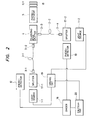
- Fig. 2 there is shown an arrangement of light sources 1-1 and 1-2 such as LEDs; splitters 17-1 and 17-2 for respectively guiding the light emitted from the light sources 1-1 and 1-2 to micro lenses 3-1 and 3-4 and the light radiated from the micro lenses 3-1 and 3-4 to photodetectors 12 and 13; optical fibers 2-1 and 2-2; micro lenses 3-2 and 3-3; a polarizing beam splitter 4 used as a polarizer; a modulator element 5, which is a Pockels element wherein polarized light is modulated according to the electric field; an eighth-wave plate 6-1; a fully reflecting mirror 18; a driving circuit for alternately driving the light sources 1-1 and 1-2; a divider 16 for forming a photodetector-to-photodetector (12 to 13) output ratio; and a calculator 20 for calculating the ratio of the photodetector-to-photodetector output ratio when the light source 1-1 is turned on to same ratio when the second light source 1-2 is turned on with
- the optical sensing equipment In the optical sensing equipment thus constructed, light is allowed to pass through the splitter 17-1, is focused by the micro lens 3-1, and is incident on the optical fiber 2-1 while the light source 1-1 is turned on.
- the light is converted into a parallel beam by the micro lens 3-2, and linearly polarized light (transmitted light) in a certain direction is made incident on the Pockels element 5 by the optical beam splitter 4, whereas any other linearly polarized light (reflected light) perpendicular to the former is emitted in the direction opposite to the micro lens 3-3 and is not utilized.
- the light which has passed through the Pockels element 5 undergoes an electro-optic effect therein, undergoing a double-refractive phenomenon because of the electric field.
- the eighth-wave plate 6-1 this case is equivalent to one where it is allowed to pass through a quarter-wave phase plate once.
- the light is again modulated by the Pockels element 5 and divided by the polarizing beam splitter 4 into two polarized components perpendicularly crossing each other, these components being respectively incident on the micro-lenses 3-2 and 3-3.
- the former is made to return to the aforementioned passage and is branched off by the splitter 17-1 and then subjected to photoelectric conversion by the photodetector 12.
- the latter is focussed by the micro lens 3-3, passed through the optical fiber 2-2, changed into a parallel beam by the micro lens 3-4, branched by the splitter 17-2, and applied the photoreceiver 13 for photoelectric conversion.
- the same phenomenon is produced when the light source 1-2 is turned on, the light reflected from the polarizing beam splitter 4 in that case is made incident on the Pockels element 5.
- the transmission factor a of the unmodulated light is made free from the effects of loss fluctuations in the light sources and the optical fibers through the divisions and is 1/2, a can be accurately obtained ( a is proportional to the quantity being measured).
- the divider 10 is used to obtain the photodetector-to-photodetector (12 to 13) output ratio when the light source 1-1 is turned on and when the light source 1-2 is turned on, and the divider 20 is used to divide the former by the latter so as to calculate an output proportional to the quantity being measured.
- a Pockels element is used as a modulator element in the embodiment described above, a bismuth-silicon-oxide (Bi 12 SiO 20 ) element may be used.
- an eighth-wave plate may be inserted between the polarizer and the modulator element, and, when a magnetic field of current is measured, the length of the bismuth-germanium-oxide or bismuth-silicon-oxide element is determined so that the plane of polarization is rotated 45° in terms of rotary power.
- a material having a photoelastic effect may be used for the modulator element, and, when a pressure is to be measured, an eighth-wave plate may be inserted between the polarizer and the modulator element.
- a Faraday element may also be used as the modulator element.
- polarizing beam splitters are usable as the splitters 17-1 and 17-2.
- FIG. 3 of the drawings a second preferred embodiment of the present invention will be described.
- like reference numerals identify like elements.
- Fig. 3 there is shown an arrangement of light sources 1-1 and 1-2, splitters 17-1 and 17-2 for guiding the light emitted from the light sources 1-1 and 1-2 and light radiated from micro lenses 3-1 and 3-4 to photodetectors 12 and 13, respectively, optical fibers 2-1 and 2-2, micro lenses 3-2 and 3-3, a polarizing beam splitter 4 used as a polarizer, a modulator element 5 (Pockels element) wherein polarized light is modulated according to the electric field, a eighth-wave plate 6-1, a half-silvered mirror 21, a driving circuit for alternately driving the light sources 1-1 and 1-2, a divider 16 for calculating a ratio between the output of the photodetectors 12 and 13, and a calculator 20 for calculating the ratio of the ratio of the outputs of the photodetectors 12 and 13 when the light source 1-1 is turned on to that when the second light source 1-2 is turned with the aid of a synchronizing signal from the driving circuit 19, thereby computing an output proportional to
- the optical sensing equipment In the optical sensing equipment thus constructed, light is allowed to pass through the splitter 17-1, is focused by the micro lens 3-1, and is incident on the optical fiber 2-1 while the light source 1-1 is turned on. The light is converted into a parallel beam by the micro lens 3-2, linearly polarized by the polarizing beam splitter 4, and then made incident on the Pockels element 5, whereby it undergoes an electro-optical effect because of the electric field, causing a double-refractive phenomenon.
- the light is given an optical bias by the eighth-wave plate 6-1 because half the light is reflected by the half-silvered mirror 21 and made to pass through the eighth-wave plate 6-1 again, this is equivalent to the case where the light passes through a quarter-wave plate once.
- the reflected light is made to pass through and is modulated by the Pockels element 5 again, and then is subjected to photointensity modulation by the polarizing beam splitter 4. Moreover, the light is again made to pass through the micro lens 3-2, the optical fiber 2-1, and the micro lens 3-1, and is branched off by the splitter 17-1 before being incident on the photodetector 12.
- the light transmitted through the half-silvered mirror 21 is not affected by photointensity modulation, even if an electric field is applied thereto.
- the light is incident on the micro lens 3-3 and made to pass through the micro lens 3-4, branched off in the splitter 17-2, and is incident on the photodetector 13.
- the light source 1-2 when the light source 1-2 is turned on, the light passes through the splitter 17-2, the micro lens 3-4, the optical fiber 2-2, and the micro lens J-3.
- Half the light is reflected by the half-silvered mirror 21 and made to follow the aforedescribed patb, being subjected to photoelectric conversion in the photodetector 13.
- half the light transmitted through the half-silvered mirror 21 is made to pass through the eighth-wave plate 6-1, the Pockels element 5, and the polarizing beam splitter 4 and is then incident on the micro lens 3-2, it is resistant to photointensity modulation by the electric field.
- the light is made to pass through the optical fiber 2-1, the micro lens 3-1, branched off by the splitter 17-1, and is then subjected to photoelectric conversion.
- the light sources 1-1 and 1-2 are alternately driven by the driving circuit 19 on a time sharing basis.
- the divider 16 takes the ratio between the outputs of the photodetectors 12 and 13 once while the light source 1-1 is turned on and again while the light source 1-2 is turned on, synchronously with the signal from the driving circuit 19, to thus compute an output proportional to the quantity being measured.
- the magnitude of the electric field can be measured without being affected by fluctuations of the light source and the optical fiber.
- a Pockels element is used as a modulator element in the embodiment above, as in the case of the first embodiment, a bismuth-germanium-oxide (Bi 12 SiO 2 ) element may be used.
- an eighth-wave plate may be inserted between the polarizer and the modulator element, and when a magnetic field or current is to be measured, the length of the bismuth-germanium-oxide or bismuth-silicon-oxide element should be determined so that the plate of polarization is rotated 45° in terms of rotary power.
- a material having a photoelastic effect may be used for the modulator element.
- an eighth-wave plate may be inserted between the polarizer and the modulator element.
- a Faraday element may also be used as the modulator element.
- polarizing beam splitters are usable as the splitters 17-1, 17-2.
Abstract
Description
- The present invention relates to optical sensing apparatus utilizing polarized light, and more specifically to an optical sensing apparatus for optically measuring the quantity of light transmitted through an optical fiber.
- Fig. 1 of the accompanying drawings is a block diagram illustrating a conventional optical sensing equipment utilizing polarized light. In Fig. 1, there is shown an arrangement of a light source 1, an
optical fiber 2, a micro lens 3, and apolarizer 4, wherein the light emitted from the light source 1 is changed by the micro lens 3 into a parallel beam, which passes through theoptical fiber 2 before being converted by thepolarizer 4 into linearly polarized light. - The arrangement includes a
photoelastic element 5, a quarter-wave plate 6, ananalyzer 7 for dividing the light into two vertically polarized components,micro lenses optical fibers photodetectors adder 14, asubtractor 15, and adivider 16. - The
photoelastic element 5 is arranged so that a pressure being measured is applied to one face thereof. A double-refractive phenomenon is caused due to the applied pressure. For instance, provided that thephotoelastic element 5 is an isotropic medium, the refractive index in the direction in which the pressure is applied becomes different from the refractive indexes in the two directions perpendicular thereto. Accordingly, if a light beam having a field component in the pressure-applied direction and another light beam having a field component perpendicular to the former are simultaneously incident on thephotoelastic element 5, a phase difference will occur at the output thereof. For instance, if the linearly polarized light of the output of thepolarizer 4 is incident on thephotoelastic element 5 at an angle of 45° with respect to the optical axis, the output of thephotoelastic element 5 will be elliptically polarized in an amount depending on the pressure. - The elliptically polarized light is given, by the quarter-
wave plate 6,a phase difference of 90° and an optical bias, and then divided by theanalyzer 7 into two polarized components perpendicular to each other. The two components are focused by themicro lenses optical fibers photodetectors - The sum of and difference between the photodetector outputs are determined by the
adder 14 and thesubtractor 15, whereas the division of them is carried out by thedivider 16. An output is thereby produced indicative of the pressure, which output is not affected by variations in the intensity of the light source 1. - Although the
photoelastic element 5 is employed as a sensor element in the aforementioned example in which a pressure is measured, a Faraday element or Pockels element may be used in the case of measuring a magnetic or electric magnetic field. - Since the photomodulated light is transmitted through the two
optical fibers optical fiber 2 through themicro lens 9, the conventional optical sensing equipment thus constructed has such a disadvantage that optical loss fluctuations between theoptical fibers - The invention is intended to eliminate such a drawback. It is therefore an object of the present invention to provide an optical sensing equipment capable of measuring a quantity accurately without being affected by loss fluctuations of the light source, optical fibers, etc.
- In the optical sensing equipment according to the present invention, only two optical fibers are connected to optical sensor means, each optical fiber being provided with a light source and a photodetector at the other end thereof, and the light sources are alternately driven on a time division basis. Two polarized components perpendicular to each other are modulated by reflex optical sensor means and subjected to photoelectric conversion by the photodetector at the end of each optical fiber and a photodetector at the end of each optical fiber, and a photodetector-to-photodetector output ratio is obtained synchronously with the generation of an output by the light source before being subjected to division. With this arrangement, an optical sensing equipment is provided which is free from the affects of transmission loss fluctuations in the optical fibers.
- In another embodiment of the invention, in order to modulate one of two light sources, a half-silvered mirror is provided at the end of the optical sensor means. By taking a output ratio of one photodetector to another photodetector when the respective light sources are turned on, and further taking a ratio of those two ratios, the effects of losses in the optical fibers and fluctuations of the light sources are eliminated in the optical sensing equipment according to the present invention.
- In accordance with the present invention, as only two optical fibers are connected to the optical sensor means, each optical fiber being provided with a light source and a photoreceiver at the other end thereof, and the light sources are alternately driven in a time division basis and then a photodetector-to-photodetector ratio is subjected to division for obtaining an output proportional to the quantity being measured, all effects of transmission loss fluctuations in the optical fibers are avoided.
-
- Fig. 1 is a block diagram of a conventional optical sensing equipment;
- Fig. 2 is a block diagram of an optical sensing equipment embodying the present invention; and
- Fig. 3 is a block diagram of another embodiment of an optical sensing equipment of the invention.
- Referring now to the drawings, preferred embodiments of the present invention will be described.
- In Fig. 2, there is shown an arrangement of light sources 1-1 and 1-2 such as LEDs; splitters 17-1 and 17-2 for respectively guiding the light emitted from the light sources 1-1 and 1-2 to micro lenses 3-1 and 3-4 and the light radiated from the micro lenses 3-1 and 3-4 to
photodetectors beam splitter 4 used as a polarizer; amodulator element 5, which is a Pockels element wherein polarized light is modulated according to the electric field; an eighth-wave plate 6-1; a fully reflectingmirror 18; a driving circuit for alternately driving the light sources 1-1 and 1-2; adivider 16 for forming a photodetector-to-photodetector (12 to 13) output ratio; and acalculator 20 for calculating the ratio of the photodetector-to-photodetector output ratio when the light source 1-1 is turned on to same ratio when the second light source 1-2 is turned on with the aid of a synchronizing signal from thedriving circuit 19, thus computing an output proportional to a quantity being measured. - In the optical sensing equipment thus constructed, light is allowed to pass through the splitter 17-1, is focused by the micro lens 3-1, and is incident on the optical fiber 2-1 while the light source 1-1 is turned on. The light is converted into a parallel beam by the micro lens 3-2, and linearly polarized light (transmitted light) in a certain direction is made incident on the
Pockels element 5 by theoptical beam splitter 4, whereas any other linearly polarized light (reflected light) perpendicular to the former is emitted in the direction opposite to the micro lens 3-3 and is not utilized. The light which has passed through the Pockelselement 5 undergoes an electro-optic effect therein, undergoing a double-refractive phenomenon because of the electric field. Although the light is given an optical bias by the eighth-wave plate 6-1 again, this case is equivalent to one where it is allowed to pass through a quarter-wave phase plate once. - The light is again modulated by the
Pockels element 5 and divided by the polarizingbeam splitter 4 into two polarized components perpendicularly crossing each other, these components being respectively incident on the micro-lenses 3-2 and 3-3. The former is made to return to the aforementioned passage and is branched off by the splitter 17-1 and then subjected to photoelectric conversion by thephotodetector 12. On the other hand, the latter is focussed by the micro lens 3-3, passed through the optical fiber 2-2, changed into a parallel beam by the micro lens 3-4, branched by the splitter 17-2, and applied thephotoreceiver 13 for photoelectric conversion. Although the same phenomenon is produced when the light source 1-2 is turned on, the light reflected from the polarizingbeam splitter 4 in that case is made incident on the Pockelselement 5. - In other words, the following calculations are made:
- When the light source 1-1 is turned on,
- output of the photoreceiver 12: D1-1,
- output of the photoreceiver 13: D2-1; and
- when the light source 1-2 is turned on,
- output of the photoreceiver 12: Dl-2,
- output of the
photoreceiver 13; D2-2 are respectively:


where: - intensity of the light source 1-1 = P1,
- intensity of the light source 1-2 = P2,
- coupling factor of the splitter 17-1 = 1/2,
- transmission factor of the optical fiber 2-1 (including the micro lenses 3-1, 3-2) = K2,
- coupling factor of the splitter 17-2 = 1/2,
- transmission factor of the modulated light incident on and radiated from the polarizing
beam splitter 4, thePockels element 5, the eight-wave plate 6-1 and the fully reflectingmirror 18 = a, and - transmission factor of the unmodulated light = .
- If expression (1) is divided by expression (2) and expression (3) by expression (4), the following are obtained, respectively:


- If expression (5) is divided by expression (6),

- Thus, the factors depending on the intensities of the light sources and the transmission losses of the optical fibers are eliminated.
- Since the transmission factor a of the unmodulated light is made free from the effects of loss fluctuations in the light sources and the optical fibers through the divisions and is 1/2, a can be accurately obtained ( a is proportional to the quantity being measured).
- The
divider 10 is used to obtain the photodetector-to-photodetector (12 to 13) output ratio when the light source 1-1 is turned on and when the light source 1-2 is turned on, and thedivider 20 is used to divide the former by the latter so as to calculate an output proportional to the quantity being measured. - Although a Pockels element is used as a modulator element in the embodiment described above, a bismuth-silicon-oxide (Bi12SiO20) element may be used. When an electric field or voltage is to be measured, an eighth-wave plate may be inserted between the polarizer and the modulator element, and, when a magnetic field of current is measured, the length of the bismuth-germanium-oxide or bismuth-silicon-oxide element is determined so that the plane of polarization is rotated 45° in terms of rotary power.
- A material having a photoelastic effect may be used for the modulator element, and, when a pressure is to be measured, an eighth-wave plate may be inserted between the polarizer and the modulator element. A Faraday element may also be used as the modulator element. Moreover, polarizing beam splitters are usable as the splitters 17-1 and 17-2.
- Referring now to Fig. 3 of the drawings, a second preferred embodiment of the present invention will be described. In Figs. 2 and 3, like reference numerals identify like elements.
- In Fig. 3 there is shown an arrangement of light sources 1-1 and 1-2, splitters 17-1 and 17-2 for guiding the light emitted from the light sources 1-1 and 1-2 and light radiated from micro lenses 3-1 and 3-4 to
photodetectors polarizing beam splitter 4 used as a polarizer, a modulator element 5 (Pockels element) wherein polarized light is modulated according to the electric field, a eighth-wave plate 6-1, a half-silveredmirror 21, a driving circuit for alternately driving the light sources 1-1 and 1-2, adivider 16 for calculating a ratio between the output of thephotodetectors calculator 20 for calculating the ratio of the ratio of the outputs of thephotodetectors circuit 19, thereby computing an output proportional to the quantity being measured. - In the optical sensing equipment thus constructed, light is allowed to pass through the splitter 17-1, is focused by the micro lens 3-1, and is incident on the optical fiber 2-1 while the light source 1-1 is turned on. The light is converted into a parallel beam by the micro lens 3-2, linearly polarized by the
polarizing beam splitter 4, and then made incident on thePockels element 5, whereby it undergoes an electro-optical effect because of the electric field, causing a double-refractive phenomenon. Although the light is given an optical bias by the eighth-wave plate 6-1 because half the light is reflected by the half-silveredmirror 21 and made to pass through the eighth-wave plate 6-1 again, this is equivalent to the case where the light passes through a quarter-wave plate once. - The reflected light is made to pass through and is modulated by the
Pockels element 5 again, and then is subjected to photointensity modulation by thepolarizing beam splitter 4. Moreover, the light is again made to pass through the micro lens 3-2, the optical fiber 2-1, and the micro lens 3-1, and is branched off by the splitter 17-1 before being incident on thephotodetector 12. - The light transmitted through the half-silvered
mirror 21 is not affected by photointensity modulation, even if an electric field is applied thereto. The light is incident on the micro lens 3-3 and made to pass through the micro lens 3-4, branched off in the splitter 17-2, and is incident on thephotodetector 13. - Subsequently, when the light source 1-2 is turned on, the light passes through the splitter 17-2, the micro lens 3-4, the optical fiber 2-2, and the micro lens J-3. Half the light is reflected by the half-silvered
mirror 21 and made to follow the aforedescribed patb, being subjected to photoelectric conversion in thephotodetector 13. Although half the light transmitted through the half-silveredmirror 21 is made to pass through the eighth-wave plate 6-1, thePockels element 5, and thepolarizing beam splitter 4 and is then incident on the micro lens 3-2, it is resistant to photointensity modulation by the electric field. The light is made to pass through the optical fiber 2-1, the micro lens 3-1, branched off by the splitter 17-1, and is then subjected to photoelectric conversion. - The light sources 1-1 and 1-2 are alternately driven by the driving
circuit 19 on a time sharing basis. Thedivider 16 takes the ratio between the outputs of thephotodetectors circuit 19, to thus compute an output proportional to the quantity being measured. Hence, the magnitude of the electric field can be measured without being affected by fluctuations of the light source and the optical fiber. - For this embodiment, when the light source 1-1 is turned on,
- output of the photoreceiver 12: D1-1,
- output of the photoreceiver 13: D2-1; and
- when the light source 1-2 is turned on,
- output of the photoreceiver 12: D1-2,
- output of the photoreceiver 13: D2-2 are respectively:


- intensity of the light source 1-1 = P1,
- intensity of the light source 1-2 = P2,
- transmission factor of the splitter 17-1 on its light source side = M1,
- transmission factor of the splitter 17-1 on its photodetector side = M2,
- transmission factor of the splitter 17-2 on its light source side = L1,
- transmission factor of the splitter 17-2 on its photodetector side = L2,
- transmission factor of the optical fiber 2-1 (including the micro lenses 3-1, 3-2) = K1,
- transmission factor of the optical fiber 2-2 (including the micro lenses 3-3, 3-4) = K2,
- coupling factor of the splitter 17-2 = 1/2,
- transmission factor of the modulated light incident on and radiated from the polarized beam splitter using a combination of the
polarized beam splitter 4, thePockels element 5, the eighth-wave plate 6-1, and the half-silveredmirror 21 = α, and - transmission factor of the
Pockels element 5 and the eighth-wave plate 6-1 = 3. - If
expression 8 is divided byexpression 9 and expression (10) by expression (11), the following is obtained:

- If expression (12) is further divided by expression (13), the value obtained is proportional to 2 , and hence terms corresponding to losses of the light sources and optical fibers are eliminated. Accordingly, an optical sensing equipment free from the affects of loss fluctuations in the optical fibers and light sources is obtained.
- Although a Pockels element is used as a modulator element in the embodiment above, as in the case of the first embodiment, a bismuth-germanium-oxide (Bi12SiO2) element may be used. When an electric field or voltage is to be measured, an eighth-wave plate may be inserted between the polarizer and the modulator element, and when a magnetic field or current is to be measured, the length of the bismuth-germanium-oxide or bismuth-silicon-oxide element should be determined so that the plate of polarization is rotated 45° in terms of rotary power.
- A material having a photoelastic effect may be used for the modulator element. When a pressure is to be measured, an eighth-wave plate may be inserted between the polarizer and the modulator element. A Faraday element may also be used as the modulator element. Moreover, polarizing beam splitters are usable as the splitters 17-1, 17-2.
where:
Claims (7)
Applications Claiming Priority (4)
| Application Number | Priority Date | Filing Date | Title |
|---|---|---|---|
| JP59197250A JPS6173038A (en) | 1984-09-18 | 1984-09-18 | Light measuring device |
| JP197250/84 | 1984-09-18 | ||
| JP59197249A JPS6173037A (en) | 1984-09-18 | 1984-09-18 | Light measuring device |
| JP197249/84 | 1984-09-18 |
Publications (2)
| Publication Number | Publication Date |
|---|---|
| EP0175358A2 true EP0175358A2 (en) | 1986-03-26 |
| EP0175358A3 EP0175358A3 (en) | 1988-05-04 |
Family
ID=26510261
Family Applications (1)
| Application Number | Title | Priority Date | Filing Date |
|---|---|---|---|
| EP85111810A Ceased EP0175358A3 (en) | 1984-09-18 | 1985-09-18 | Optical sensing equipment |
Country Status (3)
| Country | Link |
|---|---|
| US (1) | US4644153A (en) |
| EP (1) | EP0175358A3 (en) |
| KR (1) | KR900000659B1 (en) |
Cited By (6)
| Publication number | Priority date | Publication date | Assignee | Title |
|---|---|---|---|---|
| EP0284214A1 (en) * | 1987-02-26 | 1988-09-28 | The University Of Liverpool | Electric current measurement |
| EP0333882A1 (en) * | 1987-09-30 | 1989-09-27 | Kabushiki Kaisha Toshiba | Fiberoptic sensor |
| EP0403892A1 (en) * | 1989-06-19 | 1990-12-27 | Iveco Magirus Aktiengesellschaft | Device for measuring a physical entity with a fibre-optic sensor |
| EP0533207A2 (en) * | 1991-09-20 | 1993-03-24 | Omron Corporation | Multi-focus optical device |
| WO2000019217A1 (en) * | 1998-09-30 | 2000-04-06 | Honeywell Inc. | In-line electro-optic voltage sensor |
| US7173706B2 (en) * | 1999-07-02 | 2007-02-06 | Otago Innovation Limited | Apparatus and method for gas sensing |
Families Citing this family (7)
| Publication number | Priority date | Publication date | Assignee | Title |
|---|---|---|---|---|
| US4712004A (en) * | 1986-08-20 | 1987-12-08 | Simmonds Precision Products, Inc. | Method and apparatus for compensating fiber optic lead and connector losses in a fiber optic sensor by using a broadband optical source and multiple wave retardation |
| US4904085A (en) * | 1988-05-04 | 1990-02-27 | Simmonds Precision Products, Inc. | Polarimetric fiber optic sensor testing apparatus |
| US4922095A (en) * | 1989-05-11 | 1990-05-01 | Conoco Inc. | Method and apparatus for sensing disturbance using fiber-optic polarization rotation |
| US5311283A (en) * | 1991-09-05 | 1994-05-10 | The Dow Chemical Company | Fiber optic probe and method for detecting optically active materials |
| US5303037A (en) * | 1992-02-24 | 1994-04-12 | Eaton Corporation | Color sensor illumination source employing a lightpipe and multiple LEDs |
| US6534977B1 (en) | 1998-10-21 | 2003-03-18 | Paul Duncan | Methods and apparatus for optically measuring polarization rotation of optical wavefronts using rare earth iron garnets |
| US11789043B2 (en) * | 2019-09-25 | 2023-10-17 | Lumiker Aplicaciones Tecnológicas S.L. | Method and apparatus for measuring the current circulating through a conductor |
Citations (6)
| Publication number | Priority date | Publication date | Assignee | Title |
|---|---|---|---|---|
| US3980567A (en) * | 1974-03-22 | 1976-09-14 | Amf Incorporated | Optical cigarette end inspection method and device |
| US4090794A (en) * | 1976-06-01 | 1978-05-23 | Fernando Benini | Optical cigarette end inspection device |
| FR2410255A1 (en) * | 1977-11-23 | 1979-06-22 | Asea Ab | OPTICAL MEASUREMENT OF PHYSICAL QUANTITIES |
| FR2427584A1 (en) * | 1978-06-02 | 1979-12-28 | Asea Ab | OPTICAL FIBER DEVICE FOR THE MEASUREMENT OF PHYSICAL QUANTITIES SUCH AS POSITION, SPEED, FORCE, PRESSURE AND OTHER SIMILAR QUANTITIES |
| JPS5724863A (en) * | 1980-07-22 | 1982-02-09 | Iwatsu Electric Co Ltd | Modulation measuring method of and apparatus for intensity of light |
| WO1984001824A1 (en) * | 1982-10-27 | 1984-05-10 | Foxboro Co | Fiber optic displacement sensor with built-in reference |
-
1985
- 1985-04-30 KR KR1019850002913A patent/KR900000659B1/en not_active IP Right Cessation
- 1985-09-18 US US06/777,135 patent/US4644153A/en not_active Expired - Fee Related
- 1985-09-18 EP EP85111810A patent/EP0175358A3/en not_active Ceased
Patent Citations (6)
| Publication number | Priority date | Publication date | Assignee | Title |
|---|---|---|---|---|
| US3980567A (en) * | 1974-03-22 | 1976-09-14 | Amf Incorporated | Optical cigarette end inspection method and device |
| US4090794A (en) * | 1976-06-01 | 1978-05-23 | Fernando Benini | Optical cigarette end inspection device |
| FR2410255A1 (en) * | 1977-11-23 | 1979-06-22 | Asea Ab | OPTICAL MEASUREMENT OF PHYSICAL QUANTITIES |
| FR2427584A1 (en) * | 1978-06-02 | 1979-12-28 | Asea Ab | OPTICAL FIBER DEVICE FOR THE MEASUREMENT OF PHYSICAL QUANTITIES SUCH AS POSITION, SPEED, FORCE, PRESSURE AND OTHER SIMILAR QUANTITIES |
| JPS5724863A (en) * | 1980-07-22 | 1982-02-09 | Iwatsu Electric Co Ltd | Modulation measuring method of and apparatus for intensity of light |
| WO1984001824A1 (en) * | 1982-10-27 | 1984-05-10 | Foxboro Co | Fiber optic displacement sensor with built-in reference |
Non-Patent Citations (1)
| Title |
|---|
| PATENT ABSTRACTS OF JAPAN, vol. 6, no. 88 (P-118)[966], 26th May 1982; & JP-A-57 024 863 (IWASAKI TSUSHINKI K.K.) 09-02-1982 * |
Cited By (10)
| Publication number | Priority date | Publication date | Assignee | Title |
|---|---|---|---|---|
| EP0284214A1 (en) * | 1987-02-26 | 1988-09-28 | The University Of Liverpool | Electric current measurement |
| EP0333882A1 (en) * | 1987-09-30 | 1989-09-27 | Kabushiki Kaisha Toshiba | Fiberoptic sensor |
| EP0333882A4 (en) * | 1987-09-30 | 1991-05-08 | Kabushiki Kaisha Toshiba | Fiberoptic sensor |
| EP0403892A1 (en) * | 1989-06-19 | 1990-12-27 | Iveco Magirus Aktiengesellschaft | Device for measuring a physical entity with a fibre-optic sensor |
| EP0533207A2 (en) * | 1991-09-20 | 1993-03-24 | Omron Corporation | Multi-focus optical device |
| EP0533207A3 (en) * | 1991-09-20 | 1993-08-04 | Omron Corporation | Multi-focus optical device |
| US5495096A (en) * | 1991-09-20 | 1996-02-27 | Omron Corporation | Multi-focus optical device |
| WO2000019217A1 (en) * | 1998-09-30 | 2000-04-06 | Honeywell Inc. | In-line electro-optic voltage sensor |
| US6122415A (en) * | 1998-09-30 | 2000-09-19 | Blake; James N. | In-line electro-optic voltage sensor |
| US7173706B2 (en) * | 1999-07-02 | 2007-02-06 | Otago Innovation Limited | Apparatus and method for gas sensing |
Also Published As
| Publication number | Publication date |
|---|---|
| KR860008445A (en) | 1986-11-15 |
| US4644153A (en) | 1987-02-17 |
| KR900000659B1 (en) | 1990-02-02 |
| EP0175358A3 (en) | 1988-05-04 |
Similar Documents
| Publication | Publication Date | Title |
|---|---|---|
| US5715058A (en) | Method and device for the optical determination of a physical quantity | |
| US4759627A (en) | Fibre-optic interferometer | |
| US4644153A (en) | Optical sensing equipment | |
| JPH0123067B2 (en) | ||
| EP0586226B1 (en) | Optical voltage electric field sensor | |
| US4909629A (en) | Light interferometer | |
| US5698847A (en) | Optical-modulation-type sensor and process instrumentation apparatus employing the same | |
| JPH02118416A (en) | Optical sensor | |
| JPH024864B2 (en) | ||
| JPS59166873A (en) | Optical applied voltage and electric field sensor | |
| JP3357734B2 (en) | Optical sensor | |
| JPS6235627B2 (en) | ||
| RU2069839C1 (en) | Device determining lateral displacements | |
| JP2509692B2 (en) | Optical measuring device | |
| JPH0376845B2 (en) | ||
| JPH0237545B2 (en) | HIKARINYORUDENKAI * JIKAISOKUTEIKI | |
| JPS6152800A (en) | Optical fiber measuring apparatus | |
| JP3235301B2 (en) | Light voltage sensor | |
| SU1741034A1 (en) | Device for measuring parameters of signal reflections from input of microwave components | |
| SU1273755A1 (en) | Fibre-type piezooptical instrument transducer | |
| SU1272258A1 (en) | Method and apparatus for measuring high voltage | |
| JPH04332817A (en) | Light applied measurement method | |
| JPS6173038A (en) | Light measuring device | |
| JPS6061893A (en) | Measuring apparatus | |
| Takahashi et al. | 2× 2 optical switch and its applications |
Legal Events
| Date | Code | Title | Description |
|---|---|---|---|
| PUAI | Public reference made under article 153(3) epc to a published international application that has entered the european phase |
Free format text: ORIGINAL CODE: 0009012 |
|
| AK | Designated contracting states |
Kind code of ref document: A2 Designated state(s): DE FR GB SE |
|
| PUAL | Search report despatched |
Free format text: ORIGINAL CODE: 0009013 |
|
| AK | Designated contracting states |
Kind code of ref document: A3 Designated state(s): DE FR GB SE |
|
| 17P | Request for examination filed |
Effective date: 19880422 |
|
| 17Q | First examination report despatched |
Effective date: 19891023 |
|
| STAA | Information on the status of an ep patent application or granted ep patent |
Free format text: STATUS: THE APPLICATION HAS BEEN REFUSED |
|
| 18R | Application refused |
Effective date: 19910128 |
|
| RIN1 | Information on inventor provided before grant (corrected) |
Inventor name: IDA, YOSHIAKIC/O MITSUBISHI DENKI K.K. |