EP0174311B1 - Enseigne lumineuse - Google Patents
Enseigne lumineuse Download PDFInfo
- Publication number
- EP0174311B1 EP0174311B1 EP84902097A EP84902097A EP0174311B1 EP 0174311 B1 EP0174311 B1 EP 0174311B1 EP 84902097 A EP84902097 A EP 84902097A EP 84902097 A EP84902097 A EP 84902097A EP 0174311 B1 EP0174311 B1 EP 0174311B1
- Authority
- EP
- European Patent Office
- Prior art keywords
- sign
- light
- illuminant
- frame
- panel
- Prior art date
- Legal status (The legal status is an assumption and is not a legal conclusion. Google has not performed a legal analysis and makes no representation as to the accuracy of the status listed.)
- Expired - Lifetime
Links
Images


Classifications
-
- G—PHYSICS
- G09—EDUCATION; CRYPTOGRAPHY; DISPLAY; ADVERTISING; SEALS
- G09F—DISPLAYING; ADVERTISING; SIGNS; LABELS OR NAME-PLATES; SEALS
- G09F13/00—Illuminated signs; Luminous advertising
- G09F13/04—Signs, boards or panels, illuminated from behind the insignia
-
- G—PHYSICS
- G09—EDUCATION; CRYPTOGRAPHY; DISPLAY; ADVERTISING; SEALS
- G09F—DISPLAYING; ADVERTISING; SIGNS; LABELS OR NAME-PLATES; SEALS
- G09F13/00—Illuminated signs; Luminous advertising
- G09F13/04—Signs, boards or panels, illuminated from behind the insignia
- G09F13/0418—Constructional details
- G09F13/0454—Slidable panels or parts
Definitions
- the present invention relates to a light sign comprising an illuminant provided with substantially parallel channels for discharge tubes, at least one translucent sign panel as a support or holder for the sign message and a frame which peripherally defines the light sign, and in which the sign panel is insertable.
- Previously known light signs of the above mentioned kind are provided with an internal, disc- shaped holder to which the discharge tube is fixed by means of clamps.
- This attachment is work requiring and the handling of the discharge tubes involves damaging risks both for the material and the mounting staff.
- the transparent panel must be attached with relatively large space to the holder disc in order to be tolerably regularly illuminated by the discharge tube and not to get a striped appearance. In that way the thickness of the sign becomes considerable, and the body of the sign as well as the supporting construction must be performed with a corresponding larger dimensions, which results not only in aesthetic but also in great practical disadvantages.
- the US-A-3.300.885 discloses a light sign of the kind mentioned in the introduction above. It comprises a frame having translucents panels supported thereby. A sign message may be adhesively secured to the outer surfaces of the panels. The panels are corrugated and arranged so that substantially parallel channels are provided therebetween. A U-shaped discharge tube is disposed between the corrugated panels.
- This type of light sign does not have any possibility of replaceable sign panels and if any operation must be done on the sign e.g. changing of a discharge tube, the whole sign with frame must be dismounted.
- the discharge tubes are placed in casted, milled or in other ways made grooves in a two part plate, where the grooves and the discharge tubes have been given the desired configuration, e.g. the shape of one or several letters, which means that the sign picture is determined by the shape of the groove, or where the discharge tube and the groove have been given a meander-shape and the sign picture is located as a separate unit in front of and/or behind the discharge tube.
- Bending the discharge tubes in grooves made in a transparent material or vice versa is a circumstantial and expensive manufacturing method. Besides the tubes need space for thermal expansion at the same time as they should be effectively fixed in the grooves, which also causes complications.
- the object of the invention is to provide a light sign especially intended to be used in such connections, where a re-signing often occurs, e.g. on taxi-cabs and where the sign should be very narrow for having a little air resistance as possible, where the re-signing should be done with a few manipulations and without weakening the frame construction of the sign.
- the light sign should further by simple means be connectible to attachments of different kinds, so that several light signs can be joined to each other forming a continuous unit e.g. for providing of screen walls for exhibition purposes.
- the numeral 1 denotes an illuminant in the form of a holder for discharge tubes 3.
- the illuminant 1 comprises a plate of a translucent plastics material, through which parallel channels 2 pass, having a square cross section and being separated by intermediate walls 4.
- the channels receive the discharge tube 3 3 inserted therein.
- Translucent panels 5 are attached outside the channel plate 1 on both sides with some space from one another, which panels are supports or holders for the text, characters, symbols or picture of the sign.
- the channel plate 1 and the panels 5 are surrounded and supported by a joint frame 9. If the sign should be one-sided, one panel 5 is replaced by a sealing disc of opaque material.
- the conventional fixing of the discharge tube 3 with clamps is eliminated.
- the discharge tubes 3 are passed into the channels of the illuminant 1, where they are received with little free space and are kept in position by the walls thereof or by means of packing rings 6, if a guiding of fixing in the channels is necessary, e.g. for counteracting vibrations if the sign is used on a motor vehicle or the like.
- the channel plate 1 e.g. acrylic plastics material, which provides a good diffusion and a regular distribution of the light from the discharge tubes, so that even when the panel 5 is located close to the plate 1 a regular illumination of the sign is obtained.
- the discharge tubes 3 are appropriately provided with maskings facing the sign panel or panels. Said maskings being in the form of narrow (e.g. 3 mm wide) white colour strakes or thin white ribbons are applied against the tube.
- Requisite electrical attachments and connections for discharge tubes can be arranged to the edges of the channel plate 1, for which purpose the channel plate has been provided with milled grooves, in which electrical attachments and coupling devices are located. These are sealed with a sealing compound so that a waterproof illuminant is obtained.
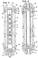
- the embodiment shown in Fig. 3 has a channel plate, the channels 2 of which are formed with a triangular or trapezodial cross section, so that with upright location of the sign, the neon tubes 3 by their weight and by wedge action are held between the inside 7 of the outer walls and the surfaces 8 of the intermediate walls.
- Fig. 4 shows a section of a light sign with similar design, where however the channel plate receiving the discharge tubes only has one plane lateral surface, which makes the sign less material requiring and lighter.
- Fig. 5 illustrates the embodiment of a sign according to the invention, provided with a frame 13, by which the sign is rotatably suspended, so that it can be lowered to a horizontal position, which facilitates mounting- and service operations.
- the sign panel 5 resp. the panels on the side facing the illuminant 1 with a reflecting, luminous coating.
- the procedure is as follows: On the inner of the sign panel, on the side facing the illuminant 1 the sign message is applied for example by screen printing, whereafter a white transparent and reflecting colour coating is applied over the screen printing.
- the sign panel can also be designed as a holder, and in this case consists of two transparent disks, a bright glass and an opaque between which the sign message printed on white paper or the like is located.
- the light sign according to the invention is so built up, that the sign panel 5 or the panels with simple manipulations can be exchanged without the whole frame 9 or even the illuminant 1 falling apart.
- the frame 9 is at least at two opposite sides, in the embodiment shown in Fig. 6-8, the long sides 14 of the sign, composed by profiled bars while the short sides of the sign 15 are each made of another profiled bar.
- the profiles which from the long sides 14 of the sign are provided with longitudinal guides 16, which are made of two flanges 17 and 18 between which there is a groove 19 for receiving a sign panel 5.
- the profile which forms the short sides 15 of the light sign lacks the groove 19 and the flange 17, which parts on the other hand are formed in an end termination profile 20, which can be passed over the resp. short side 15, through which the sign panel 5 along all side edges is surrounded by the frame 9.
- the profiles of the long sides as well as the short sides 14 and 15 are on their one internal side provided with a short distance members 21 for spacing and fixing the illuminant 1.
- a connection member can be a nut washer 23, insertable through recesses 24 arranged in the profile, and which nut washers are used for screwing the end terminations 20 firmly.
- the longitudinal grooves 22 can also be used for fastening the fitting 25 which supports the light sign.
- an apparatus cap 26 containing the electric respective electronic components which are required for starting and running the discharge tubes.
- the profiles 14 and 15 of the frame 9 are connected with each other preferably in such a way that one short side 15 is welded to the long sides 14, while the opposite short side 15 is connected by means of nipples. In this way the illuminant 1 can be drawn out of the frame anytime, which however demands a somewhat greater manual effort than if the sign panels 5 are to be changed, which occurs by the fact that one of the end terminations 20 is released whereafter the grooves 19 of the guides 16 are accessible, so that changing of sign panels can take place. If the light sign according to the invention should be used as an advertisment sign on motor vehicles, e.g. on taxicabs, the end terminations 20 are manufactured of a slightly flexible plastic material.
- the light sign can also possibly in a somewhat modified design be used as an advertisement support at exhibitions, for which purpose two or several signs are connected, so that even space defining units can be provided.
- This can be done by means of special connection members 27 resp. 28 in the form of special profile bars which partly can connect two light signs perpendicularly to each other as is shown Fig. 9 and for which purpose the profile 14, 15 on the both sides of the groove 22 is chamferred preferably at 45°, and besides the connection by means of the connection members 28 can be made, so that the light signs are located in the extension of each other, as is shown in Fig. 10.
- a reflector 29 which in the embodiment shown in Fig. 11 consists of a belt shaped disk with double-sided reflectors, in order that the discharge tubes 3 on both sides of the reflector reflect in different directions.
- the discharge tubes 3 can either be provided with the previous mentioned maskings 30 in the form of white colour strakes or thin strips or the outer channels side walls 7 of the illuminant can also preferably on the inside be provided with grooves 31.
- the reflectors 29 can consist of prism-like, appropriately extruded profiles, as is shown in Fig. 12, which are fixed in such a way in every other channels 2 in the illuminant 1, that the tips of the profile is directed towards the inner walls of the channel.
- the illuminant 1 is designed or provided with light spreading means according to what is shown in Fig. 11 and 12, the light can be designed even more compactly, so that the sign panel 5 can practically fit-up against the illuminant 1.
- the channel plate of the illuminant 1 has the cross section shown in Fig. 13 and where every individual channel has the shape of an octahedron.
- the side portions of every octahedron which also forms the side limitings of the channel plate is provided with longitudinal grooves 31, which also form contact surfaces against the sign panel 5.
- the profile bars 14 and 15 of the frame can also be designed more simply and more narrow as the distance members between the illuminant and the sign panel 5 are eliminated.
- the attachment of the detachable end terminations 20 is made by means of simple connection member 23 consisting of a screw 32 provided by anon-round portion 33, in cross section for example square and about which an 0-ring 34 is fitted.
- the whole unit is so dimensioned that a rotating of the screw 32 causes a clamping of the square portion 33 against the side edges of the longitudinal groove 22, within the area forthe mouth of the groove 22.
- a nut designed as holder-on for preventing that the screw 22 is drawn out of the groove this is also provided with a nut designed as holder-on.
- the channel plate with another cross section shape than is shown, e.g. one which connects more closely to the outer shape of the discharge tube.
Landscapes
- Physics & Mathematics (AREA)
- General Physics & Mathematics (AREA)
- Engineering & Computer Science (AREA)
- Theoretical Computer Science (AREA)
- Illuminated Signs And Luminous Advertising (AREA)
- Road Signs Or Road Markings (AREA)
- Electrochromic Elements, Electrophoresis, Or Variable Reflection Or Absorption Elements (AREA)
- Catching Or Destruction (AREA)
- Walking Sticks, Umbrellas, And Fans (AREA)
Abstract
Claims (10)
Priority Applications (1)
| Application Number | Priority Date | Filing Date | Title |
|---|---|---|---|
| AT84902097T ATE49669T1 (de) | 1983-05-04 | 1984-04-30 | Leuchtanzeige. |
Applications Claiming Priority (2)
| Application Number | Priority Date | Filing Date | Title |
|---|---|---|---|
| SE8302544 | 1983-05-04 | ||
| SE8302544 | 1983-05-04 |
Publications (2)
| Publication Number | Publication Date |
|---|---|
| EP0174311A1 EP0174311A1 (fr) | 1986-03-19 |
| EP0174311B1 true EP0174311B1 (fr) | 1990-01-17 |
Family
ID=20351079
Family Applications (1)
| Application Number | Title | Priority Date | Filing Date |
|---|---|---|---|
| EP84902097A Expired - Lifetime EP0174311B1 (fr) | 1983-05-04 | 1984-04-30 | Enseigne lumineuse |
Country Status (11)
| Country | Link |
|---|---|
| US (1) | US4805324A (fr) |
| EP (1) | EP0174311B1 (fr) |
| JP (1) | JPS60501231A (fr) |
| AU (1) | AU572156B2 (fr) |
| BR (1) | BR8407296A (fr) |
| DE (1) | DE3481097D1 (fr) |
| DK (1) | DK154369C (fr) |
| ES (1) | ES287851Y (fr) |
| FI (1) | FI852227L (fr) |
| NO (1) | NO850006L (fr) |
| WO (1) | WO1984004416A1 (fr) |
Families Citing this family (18)
| Publication number | Priority date | Publication date | Assignee | Title |
|---|---|---|---|---|
| US5433026A (en) * | 1993-06-01 | 1995-07-18 | Mcdermott; Vernon C. | Low-profile message board with side-mounted motor and moment arm |
| DK176166B1 (da) * | 1995-05-17 | 2006-11-13 | Leton Maskinfab | Skilt, såsom et vejskilt eller en vejtavle, og profil til dannelse af ramme til et sådant skilt |
| USD383497S (en) * | 1996-03-18 | 1997-09-09 | Robertson Mary N | Display device |
| AU1649797A (en) * | 1997-03-13 | 1998-09-17 | Christopher John Ball | Self-watering plant guard |
| ES2154124B1 (es) * | 1998-01-21 | 2001-11-16 | Juan Roura Y Cia S A | Dispositivo de iluminacion. |
| US6273597B1 (en) * | 2000-04-08 | 2001-08-14 | William Rolack | Roadside warning sign system |
| US6557284B2 (en) | 2001-08-27 | 2003-05-06 | Steven T. Nolan | Backlit display apparatus |
| US20050091892A1 (en) * | 2003-10-31 | 2005-05-05 | Mike Dang | Baby alert |
| US7150119B1 (en) | 2004-05-28 | 2006-12-19 | Nudo Jr Samuel | Honeycomb sign board |
| US7412790B2 (en) * | 2004-10-15 | 2008-08-19 | Thomas & Betts International, Inc. | Edge-lit panel with photo-luminescent features |
| US20080037287A1 (en) * | 2006-08-14 | 2008-02-14 | Robert Michael Krohn | Backlight panel and manufacturing method thereof |
| US20070223224A1 (en) * | 2006-03-27 | 2007-09-27 | Daniel Edelist | Illuminated privacy screen |
| US9390637B2 (en) * | 2012-07-09 | 2016-07-12 | Nicholas G Varveris | Thin-wall panel modular light box sign and display |
| US9202400B2 (en) * | 2013-04-15 | 2015-12-01 | Rose Displays, Ltd. | Frame trim extrusion |
| WO2015126481A1 (fr) * | 2014-02-21 | 2015-08-27 | Sspp Llc | Système de signalisation en couches |
| JP5961668B2 (ja) * | 2014-08-08 | 2016-08-02 | 有限会社サイン | 照明装置及びそれを用いた看板 |
| US10480752B2 (en) | 2016-02-27 | 2019-11-19 | Svv Technology Innovations, Inc. | Structurally reinforced illumination panels and a method of making the same |
| JP6241961B2 (ja) * | 2016-06-27 | 2017-12-06 | 有限会社サイン | 照明装置及びそれを用いた看板 |
Family Cites Families (47)
| Publication number | Priority date | Publication date | Assignee | Title |
|---|---|---|---|---|
| US1086960A (en) * | 1913-07-18 | 1914-02-10 | William K Waterman | Tablet. |
| FR540439A (fr) * | 1921-07-23 | 1922-07-11 | Lampe électrique de vitrine à cache interchangeable | |
| US1769243A (en) * | 1926-09-01 | 1930-07-01 | Anna E Tout | Picture mounting |
| US1961735A (en) * | 1928-08-17 | 1934-06-05 | Gen Electric Vapor Lamp Co | Electric sign |
| GB370882A (en) * | 1929-10-12 | 1932-04-14 | Philips Nv | Improvements in or relating to a method of forming luminous figures and to lighting devices |
| US1915511A (en) * | 1930-03-31 | 1933-06-27 | Flexlume Corp | Illuminated sign |
| US1879147A (en) * | 1930-05-13 | 1932-09-27 | Gen Electric Vapor Lamp Co | Illuminated sign |
| CH148405A (de) * | 1930-10-09 | 1931-07-31 | Baumann Koelliker & Cie A G | Von innen beleuchtbarer Fernrichtungsanzeiger. |
| US1858755A (en) * | 1931-01-05 | 1932-05-17 | Claude Neon Electrical Product | Illuminated sign |
| US1900467A (en) * | 1932-06-07 | 1933-03-07 | Clarence H Scruggs | Jewelry display device |
| US1964856A (en) * | 1933-03-21 | 1934-07-03 | Charles L Murray | Automatic advertising display device |
| US2080679A (en) * | 1933-04-24 | 1937-05-18 | Service Devices Inc | Luminous tube sign |
| US2052755A (en) * | 1934-06-23 | 1936-09-01 | Sealed Joint Products Co Inc | Wall construction |
| US2147959A (en) * | 1937-04-03 | 1939-02-21 | S F Arbuckle Corp | Illuminated indicium |
| US2302667A (en) * | 1939-03-15 | 1942-11-24 | Charles H Duncan | Illuminated sign |
| US2277433A (en) * | 1940-05-01 | 1942-03-24 | Edwin F Guth | Plastic diffuser |
| US2269675A (en) * | 1940-07-18 | 1942-01-13 | Preston Y Whitman | Illuminated sign for vehicles |
| US2551710A (en) * | 1945-05-04 | 1951-05-08 | Extruded Plastics Inc | Light diffusing thermoplastic tube to encircle an elongated lighting element |
| US2617501A (en) * | 1945-12-03 | 1952-11-11 | Montgomery Ward & Co | Display device |
| GB648357A (en) * | 1946-10-31 | 1951-01-03 | Rue Extrusions Ltd De | Improvements in light diffusers |
| FR949146A (fr) * | 1947-06-30 | 1949-08-22 | Saunier Anciens Ets | Sources lumineuses de grandes dimensions |
| US2651866A (en) * | 1950-07-18 | 1953-09-15 | Eastman Kodak Co | Display sign and method of making the same |
| GB706248A (en) * | 1951-09-15 | 1954-03-24 | Philips Electrical Ind Ltd | Improvements in or relating to supports for low-pressure mercury vapour discharge tubes |
| US2753640A (en) * | 1953-09-09 | 1956-07-10 | Taxineon Inc | Illuminated sign for vehicles |
| US2823475A (en) * | 1956-03-21 | 1958-02-18 | Rohm & Haas | Spectacular sign |
| US2998667A (en) * | 1958-06-05 | 1961-09-05 | Joseph W Darnell | Message conveying apparatus |
| GB912692A (en) * | 1960-03-10 | 1962-12-12 | Pearce Signs Ltd | Improvements to illuminated signs |
| US3184594A (en) * | 1963-02-05 | 1965-05-18 | Al L Siegel | Lighting fixture with interchangeable diffusers |
| US3194952A (en) * | 1963-12-23 | 1965-07-13 | Drive In Theatre Mfg Co Inc | Patio light and speaker combination |
| US3300885A (en) * | 1965-02-24 | 1967-01-31 | William H Haire | Panel type display signs |
| US3423865A (en) * | 1965-10-22 | 1969-01-28 | George K C Hardesty | Multiple image and legend display means |
| US3386197A (en) * | 1966-01-07 | 1968-06-04 | Philip D. Elfstrom | Illuminated sign |
| US3402491A (en) * | 1968-02-09 | 1968-09-24 | Xicom Inc | Portable visual display device |
| US3593446A (en) * | 1968-12-09 | 1971-07-20 | Herbert Gesner | Illuminated multicolor display device |
| US3660918A (en) * | 1970-03-27 | 1972-05-09 | Architectural Signing Inc | Negative insert holder for business directories |
| US3771245A (en) * | 1971-09-24 | 1973-11-13 | Globe Glass Manuf Co | Display system for large color transparencies |
| US3758973A (en) * | 1972-07-17 | 1973-09-18 | Magnavox Co | One piece character display device |
| US3935654A (en) * | 1972-09-20 | 1976-02-03 | Irene E. Rubin | Illuminated vehicular display sign |
| US3968359A (en) * | 1974-06-03 | 1976-07-06 | Richard Shaffer | Fluorescent lamp |
| US4139957A (en) * | 1977-03-22 | 1979-02-20 | Federal Signal Corporation | Low energy sign illumination system |
| US4186424A (en) * | 1978-02-17 | 1980-01-29 | Gte Sylvania Incorporated | Photoflash unit having lamp arrays on opposing sides |
| US4329739A (en) * | 1979-03-16 | 1982-05-11 | William Loebner | Lighted disco dance floor |
| AT368266B (de) * | 1979-09-03 | 1982-09-27 | Berndeisel & Co Johann | Werbeleuchte |
| US4303969A (en) * | 1980-05-12 | 1981-12-01 | Hamilton Jerrol D | Portable dance floor system |
| US4344244A (en) * | 1980-06-12 | 1982-08-17 | Tyke Charles R | Signage system and method of making same |
| GB2077973A (en) * | 1980-06-18 | 1981-12-23 | Adlite Electrics Ltd | Display devices |
| US4383382A (en) * | 1980-10-01 | 1983-05-17 | Self-Powered Lighting Inc. | Self-luminous safety sign |
-
1984
- 1984-04-30 DE DE8484902097T patent/DE3481097D1/de not_active Expired - Lifetime
- 1984-04-30 WO PCT/SE1984/000162 patent/WO1984004416A1/fr active IP Right Grant
- 1984-04-30 AU AU29630/84A patent/AU572156B2/en not_active Ceased
- 1984-04-30 JP JP59501936A patent/JPS60501231A/ja active Pending
- 1984-04-30 BR BR8407296A patent/BR8407296A/pt unknown
- 1984-04-30 EP EP84902097A patent/EP0174311B1/fr not_active Expired - Lifetime
- 1984-05-03 ES ES1984287851U patent/ES287851Y/es not_active Expired
- 1984-12-21 DK DK619184A patent/DK154369C/da not_active IP Right Cessation
-
1985
- 1985-01-02 NO NO850006A patent/NO850006L/no unknown
- 1985-06-04 FI FI852227A patent/FI852227L/fi not_active Application Discontinuation
-
1986
- 1986-11-19 US US06/933,346 patent/US4805324A/en not_active Expired - Fee Related
Also Published As
| Publication number | Publication date |
|---|---|
| DK154369B (da) | 1988-11-07 |
| AU572156B2 (en) | 1988-05-05 |
| US4805324A (en) | 1989-02-21 |
| ES287851Y (es) | 1987-01-16 |
| EP0174311A1 (fr) | 1986-03-19 |
| DK154369C (da) | 1989-04-10 |
| ES287851U (es) | 1986-05-16 |
| DK619184A (da) | 1985-01-17 |
| JPS60501231A (ja) | 1985-08-01 |
| FI852227A0 (fi) | 1985-06-04 |
| WO1984004416A1 (fr) | 1984-11-08 |
| NO850006L (no) | 1985-01-02 |
| DE3481097D1 (de) | 1990-02-22 |
| BR8407296A (pt) | 1986-03-25 |
| DK619184D0 (da) | 1984-12-21 |
| FI852227L (fi) | 1985-06-04 |
| AU2963084A (en) | 1984-11-19 |
Similar Documents
| Publication | Publication Date | Title |
|---|---|---|
| EP0174311B1 (fr) | Enseigne lumineuse | |
| US4693026A (en) | Changeable message outdoor advertising sign | |
| US4430819A (en) | Display sign assembly | |
| US5347736A (en) | Illuminated sign | |
| EP0746834A4 (fr) | Ensemble presentoir d'affiches et de panneaux | |
| US4587754A (en) | Illuminated display devices | |
| US3566525A (en) | Advertising sign | |
| US5584566A (en) | Backlighting light fixtures for trade show display structures | |
| EP0634736A1 (fr) | Dispositif d'affichage | |
| US4753026A (en) | Sign and signage systems | |
| US4870769A (en) | Sign | |
| US3848349A (en) | Illuminated outdoor sign | |
| US20040128890A1 (en) | Back illuminated ceiling mounted display panel | |
| EP0015747A1 (fr) | Dispositif d'exposition d'affiches | |
| US6530167B1 (en) | Mounting channel and presentation means for mounting presentation elements | |
| GB2348734A (en) | Sign decoration system | |
| GB2044976A (en) | Poster display device | |
| US4848016A (en) | Illuminated sign system | |
| EP0098124B1 (fr) | Panneaux | |
| GB2069738A (en) | Signs | |
| GB2105896A (en) | Display unit | |
| GB2077972A (en) | Panel mountings for signs | |
| EP0106574B1 (fr) | Panneau d'affichage | |
| JPH04212195A (ja) | 照明可能な突出し看板表示装置 | |
| KR0138534Y1 (ko) | 교환이 용이한 가변용 광고장치의 가동 부재 |
Legal Events
| Date | Code | Title | Description |
|---|---|---|---|
| PUAI | Public reference made under article 153(3) epc to a published international application that has entered the european phase |
Free format text: ORIGINAL CODE: 0009012 |
|
| 17P | Request for examination filed |
Effective date: 19851016 |
|
| AK | Designated contracting states |
Kind code of ref document: A1 Designated state(s): AT BE CH DE FR GB LI NL SE |
|
| 17Q | First examination report despatched |
Effective date: 19880415 |
|
| GRAA | (expected) grant |
Free format text: ORIGINAL CODE: 0009210 |
|
| AK | Designated contracting states |
Kind code of ref document: B1 Designated state(s): AT BE CH DE FR GB LI NL SE |
|
| PG25 | Lapsed in a contracting state [announced via postgrant information from national office to epo] |
Ref country code: SE Effective date: 19900117 Ref country code: NL Effective date: 19900117 Ref country code: LI Effective date: 19900117 Ref country code: FR Effective date: 19900117 Ref country code: CH Effective date: 19900117 Ref country code: BE Effective date: 19900117 Ref country code: AT Effective date: 19900117 |
|
| REF | Corresponds to: |
Ref document number: 49669 Country of ref document: AT Date of ref document: 19900215 Kind code of ref document: T |
|
| REF | Corresponds to: |
Ref document number: 3481097 Country of ref document: DE Date of ref document: 19900222 |
|
| PG25 | Lapsed in a contracting state [announced via postgrant information from national office to epo] |
Ref country code: GB Effective date: 19900430 |
|
| REG | Reference to a national code |
Ref country code: CH Ref legal event code: PL |
|
| EN | Fr: translation not filed | ||
| NLV1 | Nl: lapsed or annulled due to failure to fulfill the requirements of art. 29p and 29m of the patents act | ||
| PLBE | No opposition filed within time limit |
Free format text: ORIGINAL CODE: 0009261 |
|
| STAA | Information on the status of an ep patent application or granted ep patent |
Free format text: STATUS: NO OPPOSITION FILED WITHIN TIME LIMIT |
|
| 26N | No opposition filed | ||
| PG25 | Lapsed in a contracting state [announced via postgrant information from national office to epo] |
Ref country code: DE Effective date: 19910101 |
|
| GBPC | Gb: european patent ceased through non-payment of renewal fee |