EP0174115B1 - Method and apparatus for safer remotely controlled firing of ignition elements - Google Patents
Method and apparatus for safer remotely controlled firing of ignition elements Download PDFInfo
- Publication number
- EP0174115B1 EP0174115B1 EP85305733A EP85305733A EP0174115B1 EP 0174115 B1 EP0174115 B1 EP 0174115B1 EP 85305733 A EP85305733 A EP 85305733A EP 85305733 A EP85305733 A EP 85305733A EP 0174115 B1 EP0174115 B1 EP 0174115B1
- Authority
- EP
- European Patent Office
- Prior art keywords
- signal
- energy
- control signals
- firing
- ignition element
- Prior art date
- Legal status (The legal status is an assumption and is not a legal conclusion. Google has not performed a legal analysis and makes no representation as to the accuracy of the status listed.)
- Expired
Links
Images

Classifications
-
- F—MECHANICAL ENGINEERING; LIGHTING; HEATING; WEAPONS; BLASTING
- F42—AMMUNITION; BLASTING
- F42D—BLASTING
- F42D1/00—Blasting methods or apparatus, e.g. loading or tamping
- F42D1/04—Arrangements for ignition
- F42D1/045—Arrangements for electric ignition
- F42D1/05—Electric circuits for blasting
- F42D1/055—Electric circuits for blasting specially adapted for firing multiple charges with a time delay
Definitions
- This invention generally relates to a method and apparatus for firing an electric ignition element according to the prior art portion of claim 1 and claim 6 respectively. More particularly the invention relates to remote control firing systems wherein there is no fixed signal transmission line such as wire or explosive fusecord over at least part of the distance between the control site and the ignition elements.
- the invention is especially applicable to the firing of ignition devices in blasting detonators used to detonate blasting explosives in rock blasting operations.
- a first remotely transmitted ultrasonic signal is amplified and operates a first switch to charge a capacitor and set the system into an armed condition and a second ultrasonic signal operates a second switch to discharge the capacitor through an ignition element.
- failure of the second signal leaves the system in the "armed" condition set by the first signal for an indefinite period, because the charge on the capacitor will be maintained by the local power source until that power source is exhausted.
- the present invention provides a safer method and apparatus for the remotely controlled firing of ignition elements using a local energy source.
- a firing system wherein a low level energy control signal is transmitted to a receiver at the site of the igniton element and where the received signal is then amplified by means of an amplifier powered by a local energy source and fed to an energy storage means such as a capacitor.
- a firing control signal (or signals) is then transmitted to the receiver and used to operate a switch to discharge the energy storage means through the ignition element.
- the firing control signal may be a signal carried by the low energy control signal itself and may, for example, be a variation in frequency or interruption of the low energy control signal.
- the invention ensures that the energy storage means cannot remain in a charged condition in the event of any failure in the transmission or reception of the control signals because, should the energy control signals cease before firing of the ignition element, there will be no continued amplified energy input to the energy storage means and the charge will therefore soon be dissipated (either by internal leakage or, if desired, by auxiliary energy dissipation means, such as a current sink, which may be included in the system). Similarly, if the ignition element is not fired in reasonable time, the charge will naturally drain away from the energy storage means when the transmission of the low energy control signal is stopped.
- a method of firing an electric ignition element at an ignition site from a control site remote from said ignition site comprises:
- an apparatus for electrically igniting an ignition element from the local energy source using remotely generated control signals transmitted over a distance of which at least a part contains no fixed transmission line comprises:
- An ignition assembly comprises the aforedescribed apparatus and an ignition element connected thereto to receive electrical energy from energy storage means.
- the firing control means may comprise
- signal discriminator means also connected to said signal receiving means for identifying control signals
- switch means responsive to said discriminator means for discharging said energy storage means through said ignition element in response to identification of at least one characteristic firing control signal.
- the firing control signal or signals may advantageously be generated by modifying the low energy control signal.
- the low energy control signal may be in the form of a periodic wave of predetermined frequency which is controllably interrupted or modified for predetermined durations to generate the firing control signals.
- the signal discriminator means then advantageously includes pulse length discriminator means for detecting modified segments of predetermined duration in the received control signals as the firing control signals.
- Suitable signal generators and signal discriminators are per se known and used in systems for firing blasting detonators. A signal generator and a pulse length discriminator suitable for use in the present invention has been described in British Patent Specification No. 2,015,791 B.
- a low energy control signal is transmitted at about 20 kHz and the firing control signals are generated by interrupting the low energy control signal for one or more cycles.
- the signal discriminator will then be preset to respond to an interruption of a length within predetermined limits. Typically the interruption may be in the range of 100 to 200 microseconds.
- the signal discriminator may be preset to respond to the first firing control signal or it may include counting means to enable it to respond as required to a plurality of firing control signals individually or in sequence.
- the signal discriminator preferably comprises further means to detect the absence of low energy control signals, failure to receive a predetermined number of normal firing control signals, or failure to fire the ignition element within a predetermined time, and in any of these circumstances, to effect dissipation of the charge from the energy storage means.
- the switch means conveniently comprises logic circuitry incorporating switching transistors arranged to conduct current to the ignition element on receipt of appropriate inputs from the signal discriminator means.
- the power source is conveniently a low voltage, typically 6-18 volt, electric battery and the storage means is conveniently a capacitor.
- the internal impedance of the power source is sufficiently high to prevent firing of the ignition element in the event of the ignition element being accidentally connected directly across the power source.
- the energy signal from the amplifier will, in the preferred embodiments of the system, be an A.C. energy signal, the energy signal will usually be rectified before being fed to the capacitor and for this purpose a rectifier is conveniently included in the amplifier output to the energy storage means.
- the output from the amplifier is preferably coupled to the energy storage means through an element that does not pass D.C. currents (e.g., a capacitor or transformer) in order to avoid any risk of the storage means receiving any current directly from the power source.
- the amplifier means may be a single-stage amplifier but preferably it is a multi-stage frequency bandpass amplifier.
- a preferred amplifier system comprises a first amplifier giving normal amplification of the received low energy signal, a second amplifier having associated bandpass filters for rejecting spurious low frequency signal such as power (50-60 H z ) frequency signals, and high frequency signals such as radio frequency signals of more than 200 kHz, and a third amplifier for amplifying the energy signal to saturation level giving the maximum output voltage which can be obtained from the power source.
- the ignition element may conveniently be any electrically operated ignition element.
- the invention may advantageously be used for firing an electric fusehead of the kind used in a blasting detonator to initiate a detonation train, the detonator being operative as required to detonate one or more further explosive charges.
- the ignition element may be an instantaneous fusehead which fires an associated charge of incendiary material immediately on discharging sufficient current through it from the energy storage means.
- a plurality of ignition elements and associated charge are required to be ignited in time delay sequence.
- the required delay may be provided as appropriate for each ignition element by including a pyrotechnic delay element after the igntion element in the ignition train.
- the required delay may advantageously more accurately be obtained by means of electronic time delay means connected in the ignition assembly and arranged to operate the switch means to fire the ignition element at a predetermined time after a predetermined control signal is identified by the discriminator as a delay time starting control signal.
- a preferred electronic time delay means includes a time delay circuit as described in British Patent Specification No. 2,015,791 B, which circuit permits the delay period of each ignition element or group of ignition elements to be set by means of the remotely generated characteristic firing control signals.
- the circuit includes an internal oscillator generating clock pulses and an internal electronic counter for counting the clock pulses. The counter is arranged to start counting clock pulses when a first characteristic firing control signal is identified in the signal discriminator and to stop counting when a second characteristic firing control signal is identified.
- the clock pulse count is stored for a predetermined number of clock pulses, which may be zero, the signal discriminator means identifies a delay time starting control signal, which conveniently may be the second characteristic firing control signal, and the switch means is operated to fire the ignition element after a further number of clock pulses which is a function of the stored count.
- Sequential firing of a series of ignition elements is effected by transmitting a timed series of firing control signals to the ignition elements, the signal discriminator means of each ignition element being arranged to count the firing control signals and to identify predetermined signals of said timed series as the first and second characteristic firing control signals for that particular ignition element.
- the second characteristic firing control signal is the same for all ignition elements in the sequence and the ignition elements will fire in the reversed order of the first characteristic firing control signals.
- the time delay means may be energized from the charge storage means, the amplifier output or directly from the power source.
- the amplifying means, the signal discriminator means, the delay timing means, if required, and the switch means may be included in an integrated circuit formed on a microchip which conveniently may be encapsulated with the ignition element and explosive train in the casing of a blasting detonator.
- the invention may advantageously be operated with a wide variety of signals which can be transmitted without conventional transmission connections such as conductor wires or pyrotechnic transmission lines.
- the signal generating and transmitting means may comprise means for generating and transmitting (a) radio frequency, (b) infrared, (c) electromagnetic induction (d) ultrasonic, (e) laser or (f) pressure (shock) wave signals.
- an electric signal is transmitted by electromagnetic induction using a wire inductive loop as the transmitter and an induction pick-up coil as the signal receiving means.
- a high frequency electric signal typically about 20 kHz, is passed from a generator through the induction loop and is received in the pick-up coil at the ignition site.
- the system using induction signals is especially advantageous in rock blasting operations such as blasting in quarries, because the receiving means does not need to be exposed at the mouth of a shothole, whereas systems using radio frequency, infrared, ultrasonic or laser signals generally require the receiver to be outside the shothole. The receiver can therefore be positioned deep within the shothole at the position preferred for the ignition element.
- pressure waves are more susceptible to interference from ground faults or other ground discontinuities; ultrasonic and pressure waves have low transmission velocity which causes difficulty in obtaining accurately controlled relative firing times of ignition elements fired in sequence; and the generating and transmitting equipment required for laser signals is much more expensive.
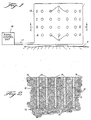
- FIGS 1 and 2 of the drawings there is shown diagrammatically, not to scale, an array of shotholes 10 drilled adjacent to a free face 11 in a rock mass 12, the shothole spread being appropriate for blasting the rock by the detonation of blasting explosive charges 13 which are loaded into the shotholes and covered with stemming material 14.
- each shothole 10 at the bottom of each explosive charge 13, is an ignition assembly 15 of the invention, the ignition element of the assembly 15 being an electric fusehead of a blasting detonator in position to detonate the explosive charge.
- a loop 16 of wire serving as an inducation loop and transmitting the control signals is located on the top surface of the rock so as to surround the shotholes 10 but not to overlie any shothole.
- the induction loop 16 is connected by a long firing cable 17 to a firing control unit (FCU) 18.
- FCU firing control unit
- the signals transmitted by the induction loop 16 are picked up by an induction pick-up coil 21 ( Figure 3) in each of the assemblies 15 and the fuseheads in the assemblies ignite and cause detonation of the explosive charges 13.
- the shot holes 10 are disposed in rows designated as A, B, C and D respectively and, in order to reduce ground vibration, the ignition assemblies in each row are arranged to fire consecutively with a preselected time delay between the firing time of the assemblies in the rows.
- the F.C.U. 18 is the remote firing control unit from which the blasting operation is controlled.
- the F.C.U. 18 includes a signal generator 19, whereby energy control signals at high frequency, typically 20 kHz, and firing control signals are generated, and a power driven amplifier 20 for amplifying the energy control signals supplied to the induction loop 16.
- the firing control signals may be generated merely by interrupting the high frequency energy signal briefly at precisely timed intervals.
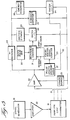
- the ignition assembly 15 has a pick-up coil 21 to receive the signal transmitted from the induction loop 16.
- the pick-up coil 21 is connected to feed the received signal to a multistage amplifier 22 (shown in detail in Figure 6) which is powered by an electric battery 23 (preferably having sufficient internal impedance to avoid firing the ignition element 26 even if directly connected there- across).
- the output signal from the amplifier 22 is fed through a half-wave rectifier 24 to a storage capacitor 25 which stores sufficient energy to fire an associated ignition element 26.
- the output signal from amplifier 22 is also fed to a pulse length discriminator 27 wherein signals formed by interruptions of the energy signal (having a duration within predetermined limits) are identified as the characteristic firing control signals and used to operate a switch 28 to discharge firing energy from the capacitor 25 through the ignition element 26.
- Instantaneous ignition elements which are not intended for use in conjunction with any delay ignition elements need only have a simple discriminator 27.
- the discriminator preferably feeds an associated firing control signal counter 29.
- the pulse length discriminator 27 may also be arranged to detect the absence of energy control signals, failure to receive a predetermined number of normal firing control signals after having started to receive same or failure to fire the ignition element within a predetermined time, and to provide an output 32 in response to any such detected inappropriate circumstance.
- Suitable energy dissipator 33 e.g., a resistor
- switch 34 may be switched across the storage capacitor 25 by switch 34 in response to such a control signal 32.
- Counter 29 is pre-set for each ignition element to respond to one or more particular (characteristic) numbers of firing control signals either to operate the switch 28 to fire the ignition element immediately on receipt of a particular number, or to effect firing of the ignition element 26 at a predetermined time after receipt of the particular numbers of signals.
- Firing of a series of ignition elements in time delay sequence is achieved by means of a clock pulse generator 30 and a reversible counter 31 wherein the clock pulses from generator 30 are counted.
- Reversible counter 31 is connected to the firing control signal counter 29 and is arranged to start a forward count of clock pulses on receipt of a first characteristic firing control signal to which counter 29 is pre-set to respond.
- reversible counter 31 On receipt of a second characteristic firing control signal (to which counter 29 is also pre-set to respond) reversible counter 31 reverses and starts counting the clock pulses backwards (i.e., the counter contents are decremented).
- counter 31 is pre-set to operate switch 28 and thus to fire ignition element 26.
- the ignition elements By identifying different firing control signals as the "first" characteristic control signals for a series of ignition elements (e.g., by differently presetting counter 29 in each row) and identifying the same firing control signal as the "second" characteristic firing control signal (in each row), the ignition elements will be fired in the reverse order of the individually identified "first" characteristic firing control signals.
- the rows of charges A, B, C and D may be fired in sequence with, for example, 25 millisecond delay between the firing of the rows, by first transmitting low energy control signals to charge the capacitor 25 in each ignition assembly and then successively generating four firing control signals 1, 2, 3 and 4 at 25 millisecond intervals in the FCU
- Signal counters 29 in the ignition assemblies of rows B, C and D are pre-set to identify signals 3, 2 and 1 respectively as the "first" characteristic firing control signals (thus starting the forward count in counter 31 at different times in the different rows) and signal 4 as the "second" characteristic firing control signal (thus reversing the count in counter 31 at a common time in all rows).
- the ignition assemblies in row A are pre-set to fire instantaneously when firing control signal 4 is identified by counter 29. (These assemblies for row A thus do not really require a clock pulse generator 30 or counter 31.) On receipt of signal 4 the charges in row A will fire, followed by those in rows B, C and D at 25 millisecond intervals. It will be understood that the time delay intervals between the firing of consecutive ignition elements need not be exactly the same as the intervals between the generated control signals, as in the aforedescribed example, but may, for example, be a multiple of the intervals of the generated control signals.
- an additional output 32 may be taken from the pulse-length discriminator 27 and used to operate a safety circuit (e.g., dissipator 33 and switch 34) to discharge the capacitor 25 when the duration of an interruption in the energy signals from the amplifier exceeds a predetermined limit.
- a safety circuit e.g., dissipator 33 and switch 34
- an auxiliary static magnetic field (e.g., via a locally placed permanent magnet) may be provided around the pick-up coil 21 in order to reduce the sensitivity of the ignition assembly to inductive fields. This renders the ignition assembly inoperable even with the power source connected in the circuit. Also, by varying the intensity of the magnetic field (e.g., by varying the size or location of the magnet) the sensitivity (gain) of the ignition assembly can be controlled.
- the magnetic field is especially effective if the pick-up coil comprises a ferrite core.
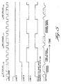
- a suitable form of signal generator 19 for supplying energy control signals and firing control signals is shown in more detail at Figure 4.
- the generator 19 comprises a power supply 41, capacitor 65, resistor 66, switch 67, start switch 42, flip-flop 43, reset line A (e.g. carrying the Q output of flip-flop 43) and a crystal oscillator 44 generating clock pulses.
- the oscillator 44 output is fed through a sine-wave shaper 45 (e.g., a passive tuned circuit with gated output control) wherein it is shaped to the form of a continuous sine-wave of a constant frequency, for example 20 kHz.
- oscillator 44 might itself generate a sinusoidal waveform and shaper 45 might be replaced with a suitable controlled gate.
- the output signal is controlled by a 2" counter 46 to last for a sufficient period to ensure full charging of the energy storage capacitors 25 in all the ignition assemblies to be fired. This period will depend on the components in the firing system but will usually not be longer than 10 seconds.
- the energy control signals are thereafter interrupted to provide firing control signals by means of a flip-flop 47, an interrupter control circuit 48 and NOR gate 49.
- switch 67 when switch 67 is closed, capacitor 65 is charged through resistor 66, and a power-on reset is applied to flip-flop 43, thereby activating reset line A and resetting the 2" counter 46 and disabling the sine-wave interrupter 48 (via resetflip-flop 47) and the sine-wave shaper 45 (via NOR gate 49).
- start switch 42 When the start switch 42 is operated, it sets flip-flop 43 and the reset line A is thereby released allowing the 2" counter 46 to operate and enabling the sine-wave shaper 45 to begin operations.
- counter 46 When counter 46 has counted sufficient pulses to ensure that each storage capacitor 25 is charged (for example for a charging time of 10 seconds at a frequency of 20 kHz, counter 46 is set to count 2 18 pulses and then to provide an output pulse) it sets flip-flop 47 which, in turn, enables the sine-wave interrupter control 48.
- the interrupter 48 may be of conventional design and is arranged to disable the sine-wave shaper 45 for an accurately determined period at regularly spaced intervals.
- an output controlling gate in the sine-wave shaper 45 is disabled for a short period every 500 cycles.
- the length of the interruption need be no more than about 3 cycles to ensure reliable detection by a receiver.
- the form of the signal from the oscillator 44, the signals through lines A, B, C and the output of Figure 4 is shown in Figure 5 for a signal generator producing at its output an initial energy control signal and subsequent firing control signals at 25 millisecond intervals.
- Amplifier 22 comprises three amplifying stages, the stages having operational amplifiers depicted as 51, 52 and 53 respectively.
- Amplifier 51 gives normal amplification of the low energy control signal received in pick-up coil 21 which is connected to amplifier 51 in parallel with a load resistor 54.
- Negative feedback is applied in conventional manner to the inverting input of amplifier 51 from the output of amplifier 51 via resistors 55 and 56, the ratio of the value of the resistors controlling the gain of the amplifier 51.
- the output of amplifier 51 is fed to a bandpass filter, which comprises a high frequency blocking filter consisting of a resistor 57 and a capacitor 58, and a low frequency blocking filter consisting of a resistor 59 and a capacitor 60, both filters having gain provided by amplifier 52.
- a bandpass filter which comprises a high frequency blocking filter consisting of a resistor 57 and a capacitor 58, and a low frequency blocking filter consisting of a resistor 59 and a capacitor 60, both filters having gain provided by amplifier 52.
- the cut-off frequencies for these filters will be chosen so as to leave passage only for the 20 kHz energy/control signals in the exemplary embodiment.
- Amplifier 52 is used as an inverting amplifier with its non-inverting input connected to ground through a resistor 61.
- the output from the bandpass filter is connected to the non-inverting input of amplifier 53.
- Negative feedback is applied in conventional manner to the inverting input of amplifier 53 from the output of amplifier 53 via resistors 62 and 63, the ratio of the values of these resistors controlling the gain of amplifier 53.
- the gain of amplifier 53 is made sufficiently large to saturate the output. Thus the output is only limited in amplitude by the size of the power supply 23.
- the output from the amplifier 53 is connected to the pulse length discriminator 27 and rectifier 24 ( Figure 3) through a resistor 64 which provides an output impedance limiting the output current. All of the amplifiers 51, 52 and 53 are powered by a split power supply 23.
- the pulse length discriminator 27, counter 29, local clock pulse generator 30, reversible counter 31 and switch 28 are well known components of electronic timing circuits. Such components and circuits may be, for example, those described in British Patent Specification No. 2,015,791 B for an electric delay device.
- the components of the firing system will be chosen to provide the requirements of a particular system.
- the components may be as follows;
- Amplifiers 51, 52, 53-LF347 QUAD operational amplifiers
Priority Applications (1)
| Application Number | Priority Date | Filing Date | Title |
|---|---|---|---|
| AT85305733T ATE45036T1 (de) | 1984-09-04 | 1985-08-13 | Verfahren und vorrichtung zum sichereren ferngesteuerten initiieren von zuendelementen. |
Applications Claiming Priority (2)
| Application Number | Priority Date | Filing Date | Title |
|---|---|---|---|
| GB8422323 | 1984-09-04 | ||
| GB8422323 | 1984-09-04 |
Publications (3)
| Publication Number | Publication Date |
|---|---|
| EP0174115A2 EP0174115A2 (en) | 1986-03-12 |
| EP0174115A3 EP0174115A3 (en) | 1987-11-19 |
| EP0174115B1 true EP0174115B1 (en) | 1989-07-26 |
Family
ID=10566240
Family Applications (1)
| Application Number | Title | Priority Date | Filing Date |
|---|---|---|---|
| EP85305733A Expired EP0174115B1 (en) | 1984-09-04 | 1985-08-13 | Method and apparatus for safer remotely controlled firing of ignition elements |
Country Status (19)
| Country | Link |
|---|---|
| US (1) | US4685396A (no) |
| EP (1) | EP0174115B1 (no) |
| JP (1) | JPS61127691A (no) |
| AT (1) | ATE45036T1 (no) |
| AU (1) | AU568226B2 (no) |
| BR (1) | BR8504243A (no) |
| CA (1) | CA1252853A (no) |
| DE (1) | DE3571873D1 (no) |
| ES (1) | ES8609694A1 (no) |
| FI (1) | FI853391L (no) |
| GB (1) | GB2164730B (no) |
| IN (1) | IN164805B (no) |
| MW (1) | MW2585A1 (no) |
| NO (1) | NO853349L (no) |
| NZ (1) | NZ213140A (no) |
| PH (1) | PH22912A (no) |
| ZA (1) | ZA856319B (no) |
| ZM (1) | ZM6085A1 (no) |
| ZW (1) | ZW13085A1 (no) |
Families Citing this family (43)
| Publication number | Priority date | Publication date | Assignee | Title |
|---|---|---|---|---|
| US4860653A (en) * | 1985-06-28 | 1989-08-29 | D. J. Moorhouse | Detonator actuator |
| GB2190730B (en) * | 1986-05-22 | 1990-10-24 | Detonix Close Corp | Detonator firing element |
| SE456939B (sv) * | 1987-02-16 | 1988-11-14 | Nitro Nobel Ab | Spraengkapsel |
| GB8718202D0 (en) * | 1987-07-31 | 1987-09-09 | Du Pont Canada | Blasting system |
| CA1326068C (en) * | 1988-02-25 | 1994-01-11 | James Robert Simon | Detonator firing system |
| US5159149A (en) * | 1988-07-26 | 1992-10-27 | Plessey South Africa Limited | Electronic device |
| US4986183A (en) * | 1989-10-24 | 1991-01-22 | Atlas Powder Company | Method and apparatus for calibration of electronic delay detonation circuits |
| FR2688583B1 (fr) * | 1992-03-10 | 1995-07-07 | Spada Entr Jean | Procede et installation de mise a feu selon une sequence determinee d'une pluralite de charges d'explosif. |
| DE4221168C1 (de) * | 1992-06-27 | 1993-11-18 | Bergwerksverband Gmbh | Verfahren zur Zündung von mehreren in Serie geschalteten Zündern und Zündmaschine mit Schaltung zur Vermeidung von Nebenschlußversagern |
| FR2701105B1 (fr) * | 1993-02-01 | 1995-04-14 | Giat Ind Sa | Dispositif de déminage. |
| US5533454A (en) * | 1994-07-18 | 1996-07-09 | Western Atlas International, Inc. | Alternating current activated firing circuit for EBW detonators |
| GB9423314D0 (en) * | 1994-11-18 | 1995-01-11 | Explosive Dev Ltd | Electrical distribution system |
| US5773749A (en) * | 1995-06-07 | 1998-06-30 | Tracor, Inc. | Frequency and voltage dependent multiple payload dispenser |
| AUPP021697A0 (en) * | 1997-11-06 | 1997-11-27 | Rocktek Limited | Radio detonation system |
| US6263989B1 (en) | 1998-03-27 | 2001-07-24 | Irobot Corporation | Robotic platform |
| DE19941301C1 (de) * | 1999-08-31 | 2000-12-07 | Honeywell Ag | Elektronischer Geschoß-Zeitzünder |
| US6265788B1 (en) * | 1999-11-05 | 2001-07-24 | Ericsson Inc. | Wireless induction loop control system |
| US6247408B1 (en) * | 1999-11-08 | 2001-06-19 | The United States Of America As Represented By The Secretary Of The Army | System for sympathetic detonation of explosives |
| DE10004582C1 (de) * | 2000-02-02 | 2001-08-30 | Honeywell Ag | Elektronischer Geschoßzünder |
| AUPQ591000A0 (en) | 2000-02-29 | 2000-03-23 | Rockmin Pty Ltd | Cartridge shell and cartridge for blast holes and method of use |
| US6584907B2 (en) * | 2000-03-17 | 2003-07-01 | Ensign-Bickford Aerospace & Defense Company | Ordnance firing system |
| US6679175B2 (en) | 2001-07-19 | 2004-01-20 | Rocktek Limited | Cartridge and method for small charge breaking |
| US6588342B2 (en) * | 2001-09-20 | 2003-07-08 | Breed Automotive Technology, Inc. | Frequency addressable ignitor control device |
| US6860206B1 (en) * | 2001-12-14 | 2005-03-01 | Irobot Corporation | Remote digital firing system |
| US7559269B2 (en) | 2001-12-14 | 2009-07-14 | Irobot Corporation | Remote digital firing system |
| US8375838B2 (en) * | 2001-12-14 | 2013-02-19 | Irobot Corporation | Remote digital firing system |
| AU2003200490B2 (en) * | 2002-02-20 | 2008-05-08 | Rocktek Ltd. | Apparatus and method for fracturing a hard material |
| CA2418387C (en) * | 2003-02-04 | 2008-06-03 | Magneto-Inductive Systems Limited | Passive inductive switch |
| EP1644689B1 (en) * | 2003-07-15 | 2010-10-20 | Detnet South Africa (Pty) Ltd | Detonator arming |
| US7594471B2 (en) * | 2004-07-21 | 2009-09-29 | Detnet South Africa (Pty) Ltd. | Blasting system and method of controlling a blasting operation |
| PE20060926A1 (es) | 2004-11-02 | 2006-09-04 | Orica Explosives Tech Pty Ltd | Montajes de detonadores inalambricos, aparatos de voladura correspondientes y metodos de voladura |
| CA2646299C (en) * | 2006-04-28 | 2014-12-02 | Orica Explosives Technology Pty Ltd | Methods of controlling components of blasting apparatuses, blasting apparatuses, and components thereof |
| US20080282925A1 (en) * | 2007-05-15 | 2008-11-20 | Orica Explosives Technology Pty Ltd | Electronic blasting with high accuracy |
| EP2006178B1 (en) * | 2007-06-19 | 2010-12-15 | Ford Global Technologies, LLC | A hybrid vehicle, a hybrid vehicle propulsion system and a method for an exhaust gas treatment device in a such a system |
| AU2009308168B2 (en) * | 2008-10-24 | 2014-10-30 | Battelle Memorial Institute | Electronic detonator system |
| WO2012061850A1 (en) | 2010-11-04 | 2012-05-10 | Detnet South Africa (Pty) Ltd | Wireless blasting module |
| AR092936A1 (es) * | 2012-10-08 | 2015-05-06 | Ael Mining Services Ltd | Detonacion de explosivos |
| US9568294B2 (en) | 2013-03-08 | 2017-02-14 | Ensign-Bickford Aerospace & Defense Company | Signal encrypted digital detonator system |
| JP6706207B2 (ja) | 2014-03-27 | 2020-06-03 | オリカ インターナショナル プライベート リミティド | 雷管ユニット、爆破システム、および爆破方法 |
| US10060716B2 (en) * | 2014-12-01 | 2018-08-28 | Matthew Creedican | Explosives manipulation using ultrasound |
| EA037944B1 (ru) | 2015-09-16 | 2021-06-10 | Орика Интернэшнл Пте Лтд | Беспроводное устройство инициирования |
| WO2017083885A1 (en) * | 2015-11-09 | 2017-05-18 | Detnet South Africa (Pty) Ltd | Wireless detonator |
| RU206899U1 (ru) * | 2020-11-27 | 2021-09-30 | Общество с ограниченной ответственностью Научно-производственная компания "Рэлсиб" (ООО НПК "Рэлсиб") | Электронный модуль детонатора с замедлением для неэлектрических систем инициирования |
Family Cites Families (10)
| Publication number | Priority date | Publication date | Assignee | Title |
|---|---|---|---|---|
| US3170399A (en) * | 1951-05-18 | 1965-02-23 | Jr Wilbur S Hinman | Radio remote control mine circuit with no current drain |
| US3171063A (en) * | 1962-07-20 | 1965-02-23 | Jersey Prod Res Co | Remote trigger arrangement for blaster |
| JPS5146248B2 (no) * | 1971-10-15 | 1976-12-08 | ||
| US3752081A (en) * | 1971-11-23 | 1973-08-14 | Bendix Corp | Blasting machine |
| JPS5028621B2 (no) * | 1972-06-23 | 1975-09-17 | ||
| US4145970A (en) * | 1976-03-30 | 1979-03-27 | Tri Electronics Ab | Electric detonator cap |
| GB2015791B (en) * | 1978-02-01 | 1982-06-03 | Ici Ltd | Selective actuation of electrical loads |
| AU518851B2 (en) * | 1978-04-26 | 1981-10-22 | Aeci Limited | Explosives |
| DE3024554C2 (de) * | 1980-06-28 | 1985-06-05 | Dynamit Nobel Ag, 5210 Troisdorf | Anordnung zur kontaktlosen Übertragung elektrischer Energie auf Flugkörper bei deren Abschuß |
| US4487125A (en) * | 1982-08-05 | 1984-12-11 | Rca Corporation | Timing circuit |
-
1985
- 1985-08-13 DE DE8585305733T patent/DE3571873D1/de not_active Expired
- 1985-08-13 EP EP85305733A patent/EP0174115B1/en not_active Expired
- 1985-08-13 GB GB08520306A patent/GB2164730B/en not_active Expired
- 1985-08-13 AT AT85305733T patent/ATE45036T1/de not_active IP Right Cessation
- 1985-08-19 NZ NZ213140A patent/NZ213140A/en unknown
- 1985-08-20 IN IN685/DEL/85A patent/IN164805B/en unknown
- 1985-08-20 PH PH32668A patent/PH22912A/en unknown
- 1985-08-20 ZW ZW130/85A patent/ZW13085A1/xx unknown
- 1985-08-20 MW MW25/85A patent/MW2585A1/xx unknown
- 1985-08-20 ZA ZA856319A patent/ZA856319B/xx unknown
- 1985-08-21 US US06/767,918 patent/US4685396A/en not_active Expired - Lifetime
- 1985-08-22 AU AU46536/85A patent/AU568226B2/en not_active Ceased
- 1985-08-22 CA CA000489271A patent/CA1252853A/en not_active Expired
- 1985-08-26 NO NO853349A patent/NO853349L/no unknown
- 1985-09-02 ZM ZM60/85A patent/ZM6085A1/xx unknown
- 1985-09-03 BR BR8504243A patent/BR8504243A/pt unknown
- 1985-09-04 JP JP60193986A patent/JPS61127691A/ja active Pending
- 1985-09-04 ES ES546710A patent/ES8609694A1/es not_active Expired
- 1985-09-04 FI FI853391A patent/FI853391L/fi not_active Application Discontinuation
Also Published As
| Publication number | Publication date |
|---|---|
| ZM6085A1 (en) | 1986-02-21 |
| GB2164730B (en) | 1988-03-16 |
| NO853349L (no) | 1986-03-05 |
| ZW13085A1 (en) | 1987-10-14 |
| EP0174115A2 (en) | 1986-03-12 |
| ES546710A0 (es) | 1986-07-16 |
| US4685396A (en) | 1987-08-11 |
| ES8609694A1 (es) | 1986-07-16 |
| FI853391L (fi) | 1986-03-05 |
| BR8504243A (pt) | 1986-07-01 |
| ZA856319B (en) | 1986-05-28 |
| MW2585A1 (en) | 1987-06-19 |
| PH22912A (en) | 1989-01-24 |
| JPS61127691A (ja) | 1986-06-14 |
| GB2164730A (en) | 1986-03-26 |
| FI853391A0 (fi) | 1985-09-04 |
| IN164805B (no) | 1989-06-03 |
| DE3571873D1 (en) | 1989-08-31 |
| AU568226B2 (en) | 1987-12-17 |
| CA1252853A (en) | 1989-04-18 |
| EP0174115A3 (en) | 1987-11-19 |
| GB8520306D0 (en) | 1985-09-18 |
| AU4653685A (en) | 1986-03-13 |
| NZ213140A (en) | 1988-02-29 |
| ATE45036T1 (de) | 1989-08-15 |
Similar Documents
| Publication | Publication Date | Title |
|---|---|---|
| EP0174115B1 (en) | Method and apparatus for safer remotely controlled firing of ignition elements | |
| EP0677164B1 (en) | Digital delay unit | |
| US4445435A (en) | Electronic delay blasting circuit | |
| US5377592A (en) | Impulse signal delay unit | |
| EP0003412A2 (en) | Electric delay device | |
| US4870902A (en) | Initiating system | |
| US6470803B1 (en) | Blasting machine and detonator apparatus | |
| GB1342507A (en) | Projectile fuse | |
| EP0694157B1 (en) | Expendable ebw firing module for detonating perforating gun charges | |
| US3255366A (en) | Pulse forming apparatus | |
| US3834310A (en) | Remote control circuit and apparatus for exploding explosives | |
| US3741124A (en) | Demolition firing device | |
| US3934514A (en) | Firing devices and processes | |
| US4799429A (en) | Programming circuit for individual bomblets in a cluster bomb | |
| GB2096415A (en) | Detonator fibring circuit | |
| CA1326068C (en) | Detonator firing system | |
| US5202532A (en) | Autonomous acoustic detonation device | |
| US3976012A (en) | Arrangement for automatic switching in electric fuses for projectiles | |
| CA1208756A (en) | Seismic recording | |
| EP0054402B1 (en) | A means for and a method of initiating explosions | |
| US4119039A (en) | Fuze system | |
| US4768127A (en) | Ignition system | |
| EP0458178A2 (en) | Autonomous acoustic detonation device | |
| US6198425B1 (en) | Pulse doppler target detecting device | |
| JP3506270B2 (ja) | 電気発破装置 |
Legal Events
| Date | Code | Title | Description |
|---|---|---|---|
| PUAI | Public reference made under article 153(3) epc to a published international application that has entered the european phase |
Free format text: ORIGINAL CODE: 0009012 |
|
| AK | Designated contracting states |
Kind code of ref document: A2 Designated state(s): AT DE FR SE |
|
| PUAL | Search report despatched |
Free format text: ORIGINAL CODE: 0009013 |
|
| AK | Designated contracting states |
Kind code of ref document: A3 Designated state(s): AT DE FR SE |
|
| 17P | Request for examination filed |
Effective date: 19871130 |
|
| 17Q | First examination report despatched |
Effective date: 19880614 |
|
| GRAA | (expected) grant |
Free format text: ORIGINAL CODE: 0009210 |
|
| AK | Designated contracting states |
Kind code of ref document: B1 Designated state(s): AT DE FR SE |
|
| REF | Corresponds to: |
Ref document number: 45036 Country of ref document: AT Date of ref document: 19890815 Kind code of ref document: T |
|
| REF | Corresponds to: |
Ref document number: 3571873 Country of ref document: DE Date of ref document: 19890831 |
|
| ET | Fr: translation filed | ||
| PLBE | No opposition filed within time limit |
Free format text: ORIGINAL CODE: 0009261 |
|
| STAA | Information on the status of an ep patent application or granted ep patent |
Free format text: STATUS: NO OPPOSITION FILED WITHIN TIME LIMIT |
|
| 26N | No opposition filed | ||
| EAL | Se: european patent in force in sweden |
Ref document number: 85305733.9 |
|
| PGFP | Annual fee paid to national office [announced via postgrant information from national office to epo] |
Ref country code: AT Payment date: 19960814 Year of fee payment: 12 |
|
| PGFP | Annual fee paid to national office [announced via postgrant information from national office to epo] |
Ref country code: SE Payment date: 19960903 Year of fee payment: 12 |
|
| PGFP | Annual fee paid to national office [announced via postgrant information from national office to epo] |
Ref country code: FR Payment date: 19970710 Year of fee payment: 13 |
|
| PGFP | Annual fee paid to national office [announced via postgrant information from national office to epo] |
Ref country code: DE Payment date: 19970723 Year of fee payment: 13 |
|
| PG25 | Lapsed in a contracting state [announced via postgrant information from national office to epo] |
Ref country code: AT Free format text: LAPSE BECAUSE OF NON-PAYMENT OF DUE FEES Effective date: 19970813 |
|
| PG25 | Lapsed in a contracting state [announced via postgrant information from national office to epo] |
Ref country code: SE Free format text: LAPSE BECAUSE OF NON-PAYMENT OF DUE FEES Effective date: 19970814 |
|
| EUG | Se: european patent has lapsed |
Ref document number: 85305733.9 |
|
| PG25 | Lapsed in a contracting state [announced via postgrant information from national office to epo] |
Ref country code: FR Free format text: LAPSE BECAUSE OF NON-PAYMENT OF DUE FEES Effective date: 19990430 |
|
| PG25 | Lapsed in a contracting state [announced via postgrant information from national office to epo] |
Ref country code: DE Free format text: LAPSE BECAUSE OF NON-PAYMENT OF DUE FEES Effective date: 19990601 |
|
| REG | Reference to a national code |
Ref country code: FR Ref legal event code: ST |