EP0172667B1 - Roller towel apparatus - Google Patents
Roller towel apparatus Download PDFInfo
- Publication number
- EP0172667B1 EP0172667B1 EP85305250A EP85305250A EP0172667B1 EP 0172667 B1 EP0172667 B1 EP 0172667B1 EP 85305250 A EP85305250 A EP 85305250A EP 85305250 A EP85305250 A EP 85305250A EP 0172667 B1 EP0172667 B1 EP 0172667B1
- Authority
- EP
- European Patent Office
- Prior art keywords
- towel
- roller
- arrangement according
- link member
- mounting means
- Prior art date
- Legal status (The legal status is an assumption and is not a legal conclusion. Google has not performed a legal analysis and makes no representation as to the accuracy of the status listed.)
- Expired
Links
Images

Classifications
-
- A—HUMAN NECESSITIES
- A47—FURNITURE; DOMESTIC ARTICLES OR APPLIANCES; COFFEE MILLS; SPICE MILLS; SUCTION CLEANERS IN GENERAL
- A47K—SANITARY EQUIPMENT; ACCESSORIES THEREFOR, e.g. TOILET ACCESSORIES
- A47K10/00—Body-drying implements; Toilet paper; Holders therefor
- A47K10/24—Towel dispensers; Toilet paper dispensers
- A47K10/28—Towel dispensers; Toilet paper dispensers dispensing a clean part and taking-up a soiled part, e.g. using rolls; with dispensers for soap or other detergents; with disinfecting or heating devices
-
- A—HUMAN NECESSITIES
- A47—FURNITURE; DOMESTIC ARTICLES OR APPLIANCES; COFFEE MILLS; SPICE MILLS; SUCTION CLEANERS IN GENERAL
- A47K—SANITARY EQUIPMENT; ACCESSORIES THEREFOR, e.g. TOILET ACCESSORIES
- A47K10/00—Body-drying implements; Toilet paper; Holders therefor
- A47K10/24—Towel dispensers; Toilet paper dispensers
- A47K10/32—Dispensers for paper towels or toilet paper
- A47K2010/3253—Dispensers for paper towels or toilet paper with one or more reserve rolls
Definitions
- the present invention relates to apparatus for dispensing roller towels.
- Roller towel cabinets are inspected periodically to check if the towel has been used up and needs replacing. Inevitably there is a delay between the exhaustion of the towel and the next inspection. This has the disadvantage that the cabinet is out of action for a period.
- the present invention seeks to overcome or reduce the above disadvantage.
- the dispensing device disclosed in that document comprises a first unit with a primary towel arranged above a second unit with a secondary towel, the secondary towel being released for use after the primary towel has become exhausted.
- the attendant either:
- the secondary towel When the secondary towel is not in use, it is concealed to a limited extent by the primary towel.
- the present invention seeks to provide an improved multiple roller towel dispensing device.
- a roller towel dispenser arrangement comprising first and second means for mounting respective roller towels, first detecting means for detecting when a roller towel on the first mounting means is exhausted, and first control means responsive to said first detecting means for allowing dispensing of a roller towel on the second mounting means, characterised in that there are provided second detecting means for detecting when the second roller towel is exhausted, and second control means responsive to said second detecting means for allowing dispensing of a roller towel on the first mounting means.
- the above arrangement has the advantage that it can provide a continuous supply of towel with the entire length of every towel being used.
- each roller through which the towel is arranged to pass, the control means keeping said rollers apart when the towel is not in use and causing the rollers to move together to allow dispensing of the towel.
- each mounting means is associated with a towel holding and concealing element which is actuated by the control means to automatically release the towel for use.
- each mounting means has at least one access door in the cabinet, the door having a plate projecting internally therefrom, and the associated towel holding and concealing element has three positions, in the first of which it holds and conceals a towel, in the second of which (with the door closed) it releases a towel for use and engages a side face of the plate, and in the third of which (with the door open) it is in the path of the plate, whereby the door cannot be closed until the element is moved out of its third position. This ensures that the door cannot be closed until the reserve side of the dispenser has been correctly set up for subsequent dispensing.
- Each mounting means may comprise a pivotally-mounted reservoir and each detecting means may comprise a link member; upon exhaustion of a towel contained in a reservoir, the reservoir pivots to actuate the respective link member.
- each control means comprises a pivotal member, actuated directly or indirectly by its respective link member, and pivoting of the pivotal member causes the rollers to move together to allow dispensing of the towel.
- the pivoting of the pivotal member may also actuate a further link member which actuates said towel holding and concealing element for automatic towel release.
- each mounting means includes a re-setting link member, whereby, upon a downward pivotal movement of the mounting means during insertion of a new towel, said re-setting link member re-sets the respective control means.
- the re-setting link member is attached to the underside of the reservoir and actuates the pivotal member to cause the rollers to move apart.
- the cabinet 20 holds two centre-less wound roller towels 10 each of 50 metre length mounted side-by-side.
- the operating mechanisms for the two towels are substantially identical and the two sides, referred to as side A and side B, operate substantially symmetrically.
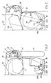
- Each towel 10 passes through a respective arrangement of combs 1, 2.
- Comb 1 is fixed betwen the side plates 30 of the mechanism.
- Comb 2 is formed by the front edge of a pivoting clean towel reservoir 9 which is biassed in an anticlockwise direction by a spring (not shown).
- a spring not shown
- the towel 10 then passes around a driver roller 4 the surface of which is covered with some medium which grips the towel without slippage.
- the towel then passes between drive roller 4 and a pinch roller 13 which is pivotally mounted on two arms 14 (see Fig. 4) and is retained in position by the spindle entering slots 33 on the side plates 30.
- Loop 11 is the length of usable towel which emerges from behind a pivoting shield 3. Towel 10 then passes under a guide bar 18 mounted on arms 38 attached to a bottom door 19 of the cabinet, and round its respective take-up roller 5 which is rotated by a roller 6, itself driven in a one- to-one ratio by the respective drive roller 4. Numeral 12 indicates the position of the fully taken-up towel.
- the flow of towel when pulled by a user, is interrupted by an escapement device 7 connected to the drive train between rollers 4 and 6.
- the drive may be transmitted by chain, belt, shafts or gears and is common to both mechanisms A and B, being driven by either roller 4A or 4B through clutch mechanisms 8A and 8B.
- rotation of either roller 4A or 4B will cause an equal rotation of both rollers 6A and 6B.
- one of the towels is accessible for use although both are prepared for use.
- the exposed towel is used as in common towel cabinet application i.e. pulling of a length oftowel from the machine causes rotation of drive roller 4.
- Roller 6 is driven from a roller 4 in a one to one ratio so that towel is wound onto movable take up roller 5 in equal length to that pulled out over roller 4.
- the towel end On exhaustion of the towel at side A, the towel end is detected by movement of the 'comb' arrangement 1, 2. This movement causes activation of a mechanism described below which exposes the reserfe towel at side B and allows the take up roller 5B to drop into contact with its driving roller 6B thus completing presentation of the towel for use.
- the mechanism for effecting changeover from dispensing of one towel to dispensing of the other towel comprises two links 15A and 15B.
- the top of link 15A is engaged and moved upwards by the side edge of reservoir 9A in its Fig. 3 position.
- the lower end of link 15A is attached to a two-arm lever 35B associated with the other side of the double towel mechanism.
- a substantially symmetrical arrangement is provided whereby a link 15B actuated by reservoir 9B is attached to a two-arm lever 35A.
- lever 35B contacts a pivotal plate 40B.
- Plate 40B has a flange 41B which holds take-up roller 5B out of contact with its driving roller 6B.
- Plate 40B is biassed by a spring (not shown) in a clockwise direction.
- link 15A is moved upwardly, lever 35B is pivoted away from plate 40B which then pivots under the effect of the spring to allow take-up roller 58 to drop into operative contact with its driving roller 6B.
- Pivoting of the plate 40B also operates a further link 16B connected to a latch 46B which releases the pivoting shield 3B containing reserve towel on side B.
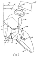
- Shield 3 is biassed (by means not shown) upwards and rearwards into the cabinet to the position shown in Fig. 2, thus releasing the reserve towel on side B.
- the towel at side A may be changed at any time during operation of the towel at side B.
- a soiled towel is removed by opening a cabinet bottom door 19.
- the soiled towel 12 together with its take up roller 5 can then be removed from the front of the cabinet.
- the take up roller is removed from the soiled towel and repositioned in its guide slots. It should be noted that the soiled towel can only be removed with arms 14 in their "up" position, Fig. 5.
- the pinch roller 13 is then lifted up from its retention slots 33 and pivoted forwards and downwards on its two arms 14.
- the clean towel reservoir 9 is then also pivoted downwards to accept a clean towel roll.
- This action operates a further linkage 17 acting on the same side which re-sets the pivoting plate 40 which holds the take up roller 5 away from the roller 6.
- This action also causes linkage 16 to reset to enable shield 3 ultimately to be locked into its closed position.
- a length of clean towel is pulled from the roll and threaded under the guide bar 18 and then wound round the take up roller 5 in the correct direction for rewinding.
- the pinch roller 13 is then pivoted upwards and repositioned in its retention slot 33 thus forming the towel loop, see Fig. 5.
- the cabinet bottom door 19 is now closed.
- a safeguard against the reserve towel being loaded without being completely covered is provided by a plate 21 attached to the top door 22 of the cabinet and positioned such that, if the pivoting shield 3 is not moved from its free position as shown in Fig. 4, then on attempting to close the door 22, plate 21 contacts shield 3 preventing the doorfrom closing. Before door 22 is opened the shield 3 engages the right hand face of plate 21 as shown in Fig. 2.
- the towel at'side B now operates as the towel at side A did during the first cycle.
- the towel at side A is released for operation, and this operation fully rewinds the towel at side B into the cabinet.
- the diameter of the rollers and gearing relative to the escapement is such that a portion length of a least 22 cm of towel is dispensed, giving a minumum capacity of 450 hand drying operations if the cabinet is not serviced.
- the width of the towel used may be approximately eight inches (20 cm). It is also intended that the cabinet shell will be configured such that either side may be converted to give a warm air drying facility.
- the towel mechanism is also capable of operating using a plastic reinforced paper 'scrim' disposable towel. Therefore the cabinet as a whole can be supplied as a completely flexible hand/face drying system capable of drying by means of any combinations of linen towel, paper scrim towel or warm air.
- the above-described description has the advantage of providing a continuous supply of towel with the entire length of every towel being used.
- the reserve towel is only released for use on exhaustion of the first towel and before being released it is completely concealed by its pivoting shield. It also has the advantage of a neat appearance since the action of advancing the replacement towel automatically winds in the exposed end of the used towel.
- the used towel can be replaced by a fresh towel at any time during use of the operational towel irrespective of which side is operational. By using a narrow towel the cabinet dimensions are kept to a minimum.
- the reservoir 9 may be arranged to move so that the growing soiled towel roll 12 will partially occupy space made available by the diminishing size of clean towel roll 10.
- reservoir 9 is of such a shape and size as to prevent contamination of clean towel areas by soiled towel areas.
- Towel metering device 7 may be a conventional time controlled arrangement. Alternatively a simple ratchet and pawl may be used to prevent the towels being pulled in the reverse direction.
- cabinet doors 19 and 22 open and close independently.
- the doors on each side e.g. 19A and 22A, may be linked so that they open and close together.
Landscapes
- Health & Medical Sciences (AREA)
- Public Health (AREA)
- Body Washing Hand Wipes And Brushes (AREA)
- Rolls And Other Rotary Bodies (AREA)
- Unwinding Webs (AREA)
- Cosmetics (AREA)
- Replacement Of Web Rolls (AREA)
- Vehicle Waterproofing, Decoration, And Sanitation Devices (AREA)
- Cleaning By Liquid Or Steam (AREA)
- Residential Or Office Buildings (AREA)
- Treatment Of Fiber Materials (AREA)
Priority Applications (1)
| Application Number | Priority Date | Filing Date | Title |
|---|---|---|---|
| AT85305250T ATE30837T1 (de) | 1984-07-24 | 1985-07-23 | Rollhandtuchgeraet. |
Applications Claiming Priority (2)
| Application Number | Priority Date | Filing Date | Title |
|---|---|---|---|
| GB848418832A GB8418832D0 (en) | 1984-07-24 | 1984-07-24 | Washroom devices |
| GB8418832 | 1984-07-24 |
Publications (2)
| Publication Number | Publication Date |
|---|---|
| EP0172667A1 EP0172667A1 (en) | 1986-02-26 |
| EP0172667B1 true EP0172667B1 (en) | 1987-11-19 |
Family
ID=10564359
Family Applications (1)
| Application Number | Title | Priority Date | Filing Date |
|---|---|---|---|
| EP85305250A Expired EP0172667B1 (en) | 1984-07-24 | 1985-07-23 | Roller towel apparatus |
Country Status (11)
| Country | Link |
|---|---|
| US (1) | US4634192A (da) |
| EP (1) | EP0172667B1 (da) |
| AT (1) | ATE30837T1 (da) |
| CA (1) | CA1236433A (da) |
| DE (2) | DE3560981D1 (da) |
| DK (1) | DK158597C (da) |
| ES (1) | ES288335Y (da) |
| GB (2) | GB8418832D0 (da) |
| HK (1) | HK6789A (da) |
| MY (1) | MY100140A (da) |
| SG (1) | SG58088G (da) |
Cited By (2)
| Publication number | Priority date | Publication date | Assignee | Title |
|---|---|---|---|---|
| DE3908253A1 (de) * | 1989-03-14 | 1990-09-20 | Schumm Erich Kg | Handtuchspender |
| DE4022003A1 (de) * | 1990-07-11 | 1992-01-16 | Schumm Erich Kg | Handtuchspender fuer eine handtuchbahn |
Families Citing this family (18)
| Publication number | Priority date | Publication date | Assignee | Title |
|---|---|---|---|---|
| GB8717546D0 (en) * | 1987-07-24 | 1987-09-03 | Crisp & Wilson Ltd | Dispensing web material from roll |
| DE3843851A1 (de) * | 1988-12-24 | 1990-06-28 | Schumm Erich Kg | Handtuchspender |
| DE69002938T2 (de) * | 1990-06-01 | 1993-12-23 | Steiner Co Lausanne Sa | System zum auswählenden Aktivieren von Spendern. |
| FR2671711B1 (fr) * | 1991-01-18 | 1993-03-26 | Elis Gie | Appareil distributeur de tissu d'essuie-mains. |
| CH689782A5 (de) * | 1995-04-19 | 1999-11-15 | Cws Ag | Verfahren und Vorrichtung zum Einfaedeln und/oder Bewegen von flaechigem Bandmaterial in einem Handtuchspender. |
| USD417109S (en) | 1998-02-02 | 1999-11-30 | Fort James Corporation | Sheet material dispenser |
| US6321963B1 (en) | 1998-02-02 | 2001-11-27 | Fort James Corporation | Sheet material dispensing apparatus and method |
| US6228454B1 (en) | 1998-02-02 | 2001-05-08 | Fort James Corporation | Sheet material having weakness zones and a system for dispensing the material |
| US6161795A (en) * | 1998-12-14 | 2000-12-19 | Kimberly-Clark Worldwide, Inc. | Surface unwind jumbo roll tissue dispenser |
| US6607160B2 (en) | 2001-07-30 | 2003-08-19 | Kimberly-Clark Worldwide | Easy loading dispenser |
| US20040130245A1 (en) * | 2003-01-06 | 2004-07-08 | Pinto Marli G. | Bathroom items dispenser |
| US10123666B2 (en) | 2012-11-30 | 2018-11-13 | Gpcp Ip Holdings Llc | System and method for reducing waste using a sheet product dispenser |
| CA2929466C (en) * | 2013-11-04 | 2019-09-03 | Wausau Paper Towel & Tissue, Llc | Dual roll paper towel dispenser |
| US11395566B2 (en) | 2016-04-11 | 2022-07-26 | Gpcp Ip Holdings Llc | Sheet product dispenser |
| US11412900B2 (en) | 2016-04-11 | 2022-08-16 | Gpcp Ip Holdings Llc | Sheet product dispenser with motor operation sensing |
| WO2020112540A1 (en) | 2018-11-28 | 2020-06-04 | Osborne Charles Agnew Jr | A sheet material dispenser assembly for selectively dispensing sheet material from a plurality of supplies of rolled sheet material |
| EP3893708B1 (en) | 2018-12-12 | 2024-11-20 | Charles Agnew Osborne, Jr. | Dispensing assembly for selectively dispensing a plurality of supplies of rolled sheet material |
| US12329327B2 (en) | 2022-02-08 | 2025-06-17 | Vsi Health And Hygiene Group, Llc | Sheet material dispenser assembly for selectively dispensing sheet material from a plurality of supplies of rolled sheet material |
Family Cites Families (6)
| Publication number | Priority date | Publication date | Assignee | Title |
|---|---|---|---|---|
| GB774970A (en) * | 1955-10-07 | 1957-05-15 | Chicago Towel Company | Multiple towel dispensing device |
| DE1778115A1 (de) * | 1968-03-29 | 1971-08-19 | Mennicken Leo | Klosettpapierrollenhalter |
| US3698653A (en) * | 1971-05-05 | 1972-10-17 | Tadasu Okamura | Toilet paper roll holding device |
| US4222621A (en) * | 1979-07-11 | 1980-09-16 | Greenlee Lois J | Device for storing and dispensing tissues, towels, and the like that are provided in the form of rolls |
| US4422585A (en) * | 1981-09-21 | 1983-12-27 | Alwin Manufacturing Company, Inc. | Toilet paper dispenser with sliding mandrels |
| US4552315A (en) * | 1983-01-13 | 1985-11-12 | Maurice Granger | Rolled web dispenser |
-
1984
- 1984-07-24 GB GB848418832A patent/GB8418832D0/en active Pending
-
1985
- 1985-07-23 AT AT85305250T patent/ATE30837T1/de not_active IP Right Cessation
- 1985-07-23 EP EP85305250A patent/EP0172667B1/en not_active Expired
- 1985-07-23 GB GB08518618A patent/GB2162151B/en not_active Expired
- 1985-07-23 DK DK334285A patent/DK158597C/da not_active IP Right Cessation
- 1985-07-23 DE DE8585305250T patent/DE3560981D1/de not_active Expired
- 1985-07-23 DE DE198585305250T patent/DE172667T1/de active Pending
- 1985-07-24 ES ES1985288335U patent/ES288335Y/es not_active Expired
- 1985-07-24 US US06/758,509 patent/US4634192A/en not_active Expired - Fee Related
- 1985-07-24 CA CA000487411A patent/CA1236433A/en not_active Expired
-
1987
- 1987-05-14 MY MYPI87000647A patent/MY100140A/en unknown
-
1988
- 1988-09-08 SG SG580/88A patent/SG58088G/en unknown
-
1989
- 1989-01-19 HK HK67/89A patent/HK6789A/xx unknown
Cited By (2)
| Publication number | Priority date | Publication date | Assignee | Title |
|---|---|---|---|---|
| DE3908253A1 (de) * | 1989-03-14 | 1990-09-20 | Schumm Erich Kg | Handtuchspender |
| DE4022003A1 (de) * | 1990-07-11 | 1992-01-16 | Schumm Erich Kg | Handtuchspender fuer eine handtuchbahn |
Also Published As
| Publication number | Publication date |
|---|---|
| DK158597B (da) | 1990-06-18 |
| DK158597C (da) | 1991-01-07 |
| ATE30837T1 (de) | 1987-12-15 |
| DE172667T1 (de) | 1987-02-26 |
| ES288335U (es) | 1985-12-16 |
| DE3560981D1 (en) | 1987-12-23 |
| GB8418832D0 (en) | 1984-08-30 |
| GB8518618D0 (en) | 1985-08-29 |
| CA1236433A (en) | 1988-05-10 |
| EP0172667A1 (en) | 1986-02-26 |
| ES288335Y (es) | 1986-07-16 |
| MY100140A (en) | 1990-01-18 |
| DK334285A (da) | 1986-01-25 |
| DK334285D0 (da) | 1985-07-23 |
| HK6789A (en) | 1989-01-27 |
| SG58088G (en) | 1989-01-27 |
| GB2162151A (en) | 1986-01-29 |
| US4634192A (en) | 1987-01-06 |
| GB2162151B (en) | 1987-03-25 |
Similar Documents
| Publication | Publication Date | Title |
|---|---|---|
| EP0172667B1 (en) | Roller towel apparatus | |
| US4487375A (en) | Roll transfer mechanism for web material dispenser | |
| US4676131A (en) | Electric paper cabinet | |
| US6237871B1 (en) | Paper towel transfer apparatus | |
| RU2447824C2 (ru) | Раздаточный аппарат для выдачи обтирочных материалов | |
| US3858951A (en) | Towel dispenser | |
| US5762287A (en) | Center pull towel dispenser with towel transfer mechanism | |
| JP3710819B2 (ja) | タオルディスペンサにおける平らなストリップ材料の装填 | |
| US4848854A (en) | Continuous towel cabinets | |
| GB2101756A (en) | Automatic film loading and rewind. | |
| US4573750A (en) | Dispensing apparatus | |
| US3826548A (en) | Dispenser for hand towelling | |
| US4370041A (en) | Combination photographing and developing apparatus | |
| US3971607A (en) | Fabric hand towel dispenser | |
| US4818042A (en) | Cloth towel dispenser and method for the operation thereof | |
| FI58258C (fi) | Handduksutmatningsanordning | |
| US2206951A (en) | Towel cabinet and mechanism therefor | |
| US5184885A (en) | Cloth towel dispenser with two adjoining units | |
| JPH01270830A (ja) | 巻きタオルディスペンサー | |
| US4073422A (en) | Ticket dispenser | |
| FI91825B (fi) | Kaksi toisiinsa liittyvää pyyheyksikköä sisältävä kangaspyyheautomaatti | |
| EP0534792B1 (en) | Towel cabinet | |
| US3522978A (en) | Hand towel dispensing appliance | |
| WO1990001286A1 (en) | Dispenser for rolled webs | |
| US1976087A (en) | Towel dispensing apparatus |
Legal Events
| Date | Code | Title | Description |
|---|---|---|---|
| PUAI | Public reference made under article 153(3) epc to a published international application that has entered the european phase |
Free format text: ORIGINAL CODE: 0009012 |
|
| AK | Designated contracting states |
Designated state(s): AT BE CH DE FR IT LI NL SE |
|
| 17P | Request for examination filed |
Effective date: 19860409 |
|
| 17Q | First examination report despatched |
Effective date: 19861208 |
|
| DET | De: translation of patent claims | ||
| ITF | It: translation for a ep patent filed | ||
| GRAA | (expected) grant |
Free format text: ORIGINAL CODE: 0009210 |
|
| AK | Designated contracting states |
Kind code of ref document: B1 Designated state(s): AT BE CH DE FR IT LI NL SE |
|
| REF | Corresponds to: |
Ref document number: 30837 Country of ref document: AT Date of ref document: 19871215 Kind code of ref document: T |
|
| REF | Corresponds to: |
Ref document number: 3560981 Country of ref document: DE Date of ref document: 19871223 |
|
| ET | Fr: translation filed | ||
| PLBE | No opposition filed within time limit |
Free format text: ORIGINAL CODE: 0009261 |
|
| STAA | Information on the status of an ep patent application or granted ep patent |
Free format text: STATUS: NO OPPOSITION FILED WITHIN TIME LIMIT |
|
| 26N | No opposition filed | ||
| PGFP | Annual fee paid to national office [announced via postgrant information from national office to epo] |
Ref country code: CH Payment date: 19910621 Year of fee payment: 7 |
|
| PGFP | Annual fee paid to national office [announced via postgrant information from national office to epo] |
Ref country code: FR Payment date: 19910705 Year of fee payment: 7 Ref country code: BE Payment date: 19910705 Year of fee payment: 7 |
|
| PGFP | Annual fee paid to national office [announced via postgrant information from national office to epo] |
Ref country code: SE Payment date: 19910717 Year of fee payment: 7 |
|
| PGFP | Annual fee paid to national office [announced via postgrant information from national office to epo] |
Ref country code: DE Payment date: 19910724 Year of fee payment: 7 |
|
| ITTA | It: last paid annual fee | ||
| PGFP | Annual fee paid to national office [announced via postgrant information from national office to epo] |
Ref country code: NL Payment date: 19910731 Year of fee payment: 7 Ref country code: AT Payment date: 19910731 Year of fee payment: 7 |
|
| PG25 | Lapsed in a contracting state [announced via postgrant information from national office to epo] |
Ref country code: AT Effective date: 19920723 |
|
| PG25 | Lapsed in a contracting state [announced via postgrant information from national office to epo] |
Ref country code: SE Effective date: 19920724 |
|
| PG25 | Lapsed in a contracting state [announced via postgrant information from national office to epo] |
Ref country code: LI Effective date: 19920731 Ref country code: CH Effective date: 19920731 Ref country code: BE Effective date: 19920731 |
|
| BERE | Be: lapsed |
Owner name: DUDLEY INDUSTRIES LTD Effective date: 19920731 |
|
| PG25 | Lapsed in a contracting state [announced via postgrant information from national office to epo] |
Ref country code: NL Effective date: 19930201 |
|
| NLV4 | Nl: lapsed or anulled due to non-payment of the annual fee | ||
| PG25 | Lapsed in a contracting state [announced via postgrant information from national office to epo] |
Ref country code: FR Effective date: 19930331 |
|
| REG | Reference to a national code |
Ref country code: CH Ref legal event code: PL |
|
| PG25 | Lapsed in a contracting state [announced via postgrant information from national office to epo] |
Ref country code: DE Effective date: 19930401 |
|
| REG | Reference to a national code |
Ref country code: FR Ref legal event code: ST |
|
| EUG | Se: european patent has lapsed |
Ref document number: 85305250.4 Effective date: 19930204 |