EP0171750A2 - Système de télécommunications à services intégrés pour services à bande étroite et large bande - Google Patents
Système de télécommunications à services intégrés pour services à bande étroite et large bande Download PDFInfo
- Publication number
- EP0171750A2 EP0171750A2 EP85109940A EP85109940A EP0171750A2 EP 0171750 A2 EP0171750 A2 EP 0171750A2 EP 85109940 A EP85109940 A EP 85109940A EP 85109940 A EP85109940 A EP 85109940A EP 0171750 A2 EP0171750 A2 EP 0171750A2
- Authority
- EP
- European Patent Office
- Prior art keywords
- optical
- subscriber
- electrical
- kfo
- broadband
- Prior art date
- Legal status (The legal status is an assumption and is not a legal conclusion. Google has not performed a legal analysis and makes no representation as to the accuracy of the status listed.)
- Withdrawn
Links
- 230000003287 optical effect Effects 0.000 claims abstract description 53
- 230000008878 coupling Effects 0.000 claims abstract description 46
- 238000010168 coupling process Methods 0.000 claims abstract description 46
- 238000005859 coupling reaction Methods 0.000 claims abstract description 46
- 239000013307 optical fiber Substances 0.000 claims description 12
- 239000000835 fiber Substances 0.000 claims description 9
- 238000004891 communication Methods 0.000 description 11
- 230000005540 biological transmission Effects 0.000 description 9
- 230000011664 signaling Effects 0.000 description 6
- 238000006243 chemical reaction Methods 0.000 description 5
- 238000005516 engineering process Methods 0.000 description 3
- 230000008929 regeneration Effects 0.000 description 3
- 238000011069 regeneration method Methods 0.000 description 3
- 238000011161 development Methods 0.000 description 2
- 230000018109 developmental process Effects 0.000 description 2
- 101001050622 Homo sapiens KH domain-containing, RNA-binding, signal transduction-associated protein 2 Proteins 0.000 description 1
- 101001050607 Homo sapiens KH domain-containing, RNA-binding, signal transduction-associated protein 3 Proteins 0.000 description 1
- 102100023411 KH domain-containing, RNA-binding, signal transduction-associated protein 2 Human genes 0.000 description 1
- 102100023428 KH domain-containing, RNA-binding, signal transduction-associated protein 3 Human genes 0.000 description 1
- 230000004913 activation Effects 0.000 description 1
- 230000002457 bidirectional effect Effects 0.000 description 1
- 238000001514 detection method Methods 0.000 description 1
- 230000000694 effects Effects 0.000 description 1
- 238000010291 electrical method Methods 0.000 description 1
Images
Classifications
-
- H—ELECTRICITY
- H04—ELECTRIC COMMUNICATION TECHNIQUE
- H04Q—SELECTING
- H04Q11/00—Selecting arrangements for multiplex systems
- H04Q11/04—Selecting arrangements for multiplex systems for time-division multiplexing
- H04Q11/0428—Integrated services digital network, i.e. systems for transmission of different types of digitised signals, e.g. speech, data, telecentral, television signals
- H04Q11/0478—Provisions for broadband connections
-
- H—ELECTRICITY
- H04—ELECTRIC COMMUNICATION TECHNIQUE
- H04J—MULTIPLEX COMMUNICATION
- H04J2203/00—Aspects of optical multiplex systems other than those covered by H04J14/05 and H04J14/07
- H04J2203/0001—Provisions for broadband connections in integrated services digital network using frames of the Optical Transport Network [OTN] or using synchronous transfer mode [STM], e.g. SONET, SDH
- H04J2203/0003—Switching fabrics, e.g. transport network, control network
-
- H—ELECTRICITY
- H04—ELECTRIC COMMUNICATION TECHNIQUE
- H04J—MULTIPLEX COMMUNICATION
- H04J2203/00—Aspects of optical multiplex systems other than those covered by H04J14/05 and H04J14/07
- H04J2203/0001—Provisions for broadband connections in integrated services digital network using frames of the Optical Transport Network [OTN] or using synchronous transfer mode [STM], e.g. SONET, SDH
- H04J2203/0089—Multiplexing, e.g. coding, scrambling, SONET
Definitions
- Such a telecommunication system can be designed in such a way that optical fibers operated at a bit rate of 140 Mbit / s are provided as the transmission medium in the level of the subscriber lines, via which narrowband communication signals and 64 kbit / s telephony digital signals are used in the electrical multiplex , as well as broadband communication signals, such as moving picture communication signals, and via which narrowband services and broadband services also provide common signaling, and that narrowband switching devices and broadband switching devices are provided next to one another in the exchanges (preferably having a common control device) (DE-PS 2421002 );
- a star structure of the optical waveguides is to be preferred in such an integrated broadband digital network (broadband ISDN).
- the circuitry complexity in an end switching center is mainly due to the broadband subscriber line circuits, which terminate the fiber optic subscriber lines with opto-electrical and electro-optical converters and, via this converter, the following demultiplexers or preceding multiplexers with the broadband -Connect coupling arrangement and the narrowband coupling arrangement and their possibly common control device, the broadband coupling arrangement between the subscriber lines formed by at least one optical waveguide and a central electrical broadband coupling network, a subscriber coupling stage for concentrating or expanding the traffic from or to the subscriber lines can have (ISS'84 Proceedings Paper 23 C. 1. 1 ... 7, FIG 4 and 5).
- the coupling devices are set with electrical signals which are derived from the signaling characters which are transmitted in the narrowband or signaling channels via the optical connecting lines. At least in this respect, therefore, an opto-electrical conversion must take place, and if, as stated above, broadband and narrowband signals and signaling signs are transmitted in the electrical multiplex, the entire optical signal transmitted on the optical fiber connecting line must be converted into electrical. Then electrical broadband signals can also be transmitted in this form.
- the transmission technology provided on the subscriber lines will not be optimized for extreme ranges for reasons of complexity; when switching to connecting lines, the broadband signals must therefore be regenerated in general.
- the object of the invention is to reduce the complexity of broadband connection circuits with opto-electrical and electro-optical converters for signal conversion and demultiplexers and multiplexers for fanning out or combining the broadband connections in a service-integrating broadband digital network with optical waveguide subscriber lines in a star structure. To reduce narrowband and signaling channels.
- the invention relates to an integrated telecommunications system for narrowband and broadband services, with narrowband coupling arrangements and broadband coupling arrangements provided next to one another in switching centers, such a broadband coupling arrangement between the subscriber lines formed by at least one optical waveguide and a central electrical broadband coupling network, a subscriber coupling stage for concentrating or expanding the traffic from or to the subscriber lines.
- this telecommunication system is characterized in that an optical coupling network is provided as the subscriber coupling stage, to which on the one hand the optical waveguide subscriber connection lines are connected and on the other hand via opto-electrical / electro provided only in the intermediate lines running between the optical subscriber coupling stage and the central electrical broadband coupling network -optical converter and electrical demultiplexer / muttiplexer is connected to the electrical broadband switching network;
- signal regenerators can also be inserted between the opto-electrical converters and the electrical demultiplexers.
- the invention brings with it the advantage of not having to provide any subscriber-specific expenditure for the opto / electrical and electro / optical signal conversion, for the demultiplexing and multiplexing of broadband and narrowband channels and, if appropriate, for signal regeneration, but rather the expenditure required for this depending on to be able to reduce the traffic values to be expected on the subscriber lines by about a factor of 4 ... 10.
- the aforementioned subsequent signal regeneration makes it possible that the transmission technology requirements for the optical concentration or expansion stage need not be great.
- optical coupling points are not taken into account in any case that the range of the connection is not reduced too much by the signal attenuation caused by the optical coupling network, such a reduction can also be counteracted by further developing the invention in addition to the optical coupling points the optical subscriber coupling stage, optical amplifiers are also provided in the optical signal paths.
- connection incentives in the optical waveguide subscriber connection lines which are not terminated by an individual broadband subscriber circuit in order to be able to recognize connection incentives in the optical waveguide subscriber connection lines which are not terminated by an individual broadband subscriber circuit, in the development of the invention all free optical waveguide subscriber lines can be cyclically connected to a connection circuit of the electrical broadband coupling network which is kept free of connections. An activation attempt by the subscriber concerned, for example in the form of switching on the light or in the form of emitting a special bit pattern, can then take effect in the switching control via this connection circuit.
- fiber-optic subscriber lines not involved in a connection can be darkened; in a further embodiment of the invention, however, it is also possible for the optical fiber subscriber connection lines not involved in a connection to be acted upon by an optical office clock signal in order, for example, to maintain synchronism between subscriber stations and the network.
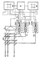
- a subscriber lines Ah1, AI2 ... AII forming a star network are provided, each of which may be formed by (with bidirectional operation) one or also (with unidirectional operation) two optical fibers and via the subscriber stations (not shown in the drawing) of the telecommunication system are connected to their associated switching center.
- narrowband communication signals such as 64 kbit / s digital telephone signals and control signals (signaling characters) and broadband communication signals such as image telephony signals may be transmitted from the exchange to the exchange and in the opposite direction from the exchange to the exchange .
- a narrow-band coupling arrangement KFS transmitting electrical narrowband communication signals and a broadband switching network KFB switching through electrical broadband communication signals are provided side by side, which, as is also indicated in the drawing, can have a (at least partially) common control device VS.
- an optical switching network KFO is provided as a subscriber coupling stage concentrating or expanding the traffic to or from the subscriber connection lines, which is also provided by an adjusting device E from the Switching control VS is controllable here.
- This optical coupling network KFO to which on the one hand the fiber optic subscriber line connections A1, A12, All are directly connected, is on the other hand via intermediate lines Zl1, Zl2 ... Zlm, the number m of which is smaller than the number I of the fiber optic connecting lines the electrical coupling devices KFB, KFS connected.
- a connection shading SLM is inserted into each intermediate line ZI, which - seen in one transmission direction - has an opto / electrical converter and a subsequent electrical demultiplexer and - seen in the other transmission direction - an electrical multiplexer and a subsequent electro / optical converter, whereby , as is also indicated in the drawing, a signal regenerator R may be inserted between the opto / electrical converter and the electrical demultiplexer.
- a multiplex signal from a subscriber station via its fiber optic subscriber line Al to the exchange is switched through the optical coupling network KFO to an intermediate line ZI and thus to the connecting circuit SLM associated with this intermediate line, where it is first converted opto / electrically, then regenerated and finally into the individual signals contained therein are fanned out into a narrowband communication signal to be relayed via the narrowband switching network KFS, a control signal picked up by the switching control VS and a broadband communication signal to be relayed via the broadband coupling network KFB.
- narrowband communication signals transmitted through the narrowband switching network KFS are combined with a broadband communication signal transmitted through the broadband switching network KFB in the relevant connection circuit SLM to form an electrical multiplex signal, which is then converted electro / optically and as an optical signal from the optical section of the associated intermediate line ZI ago through the optical coupling network KFO to the relevant fiber optic subscriber line Al is switched through.
- the fiber optic subscriber connecting lines A1 the optical sections of the intermediate lines ZI and the demultiplexer outputs / multiplexer inputs of the connecting shafts SLM with the broadband switching network KFB, the narrowband switching network KFS and the switching control VS connecting branch lines ZIB, ZIS, ZID just like the connection circuits SLM itself appear in a somewhat single-core representation that, like the optical fiber subscriber connecting lines A1 but also the optical fiber sections of the intermediate lines ZI, each can be realized with two optical fibers operated in a directionally separating manner and that the intermediate line branches ZIB, ZIS, which transmit the individual electrical signals ZID will be implemented as four-wire lines.
- optical amplifiers can also be provided in the optical sections of the intermediate lines ZI without this being shown in more detail in the drawing
- each fiber-optic subscriber line Al involved in a connection is connected for the duration of the connection in question to the link-specific connection circuit SLM via whose intermediate line ZI the connection in question is expediently one of the connection shafts SLM1, SLM2, ... SLMm of such connections are kept free, and all free, ie not currently participating in a connection, fiber optic subscriber lines Al are cyclically connected to this free connection circuit SLM via the optical subscriber coupling stage KFO. It is thereby achieved that connection incentives coming from previously free subscriber lines reach the switching control VS in such a cycle and can thus be recognized by the latter.
- connection incentive can reach, for example, the connection circuit SLM in such a way that the direction of transmission leading there previously darkened optical waveguide is now lighted.
- a connection circuit SLM instead of a connection circuit SLM, a separate indication circuit can also be used to recognize a connection incentive, and then, after detection of a connection incentive, a connection is made to a connection circuit SLM.
- optical fiber subscriber lines Al In the reverse direction of transmission, free, i.e. Optical fiber subscriber lines Al not involved in a connection must also be darkened. These optical fiber subscriber line connections can, however, without this being shown in more detail in the drawing, can be acted upon by an optical office clock signal in order to be able to maintain synchronization of the free subscriber stations with respect to the network.
Landscapes
- Engineering & Computer Science (AREA)
- Computer Networks & Wireless Communication (AREA)
- Data Exchanges In Wide-Area Networks (AREA)
- Small-Scale Networks (AREA)
- Use Of Switch Circuits For Exchanges And Methods Of Control Of Multiplex Exchanges (AREA)
Applications Claiming Priority (2)
| Application Number | Priority Date | Filing Date | Title |
|---|---|---|---|
| DE3429397 | 1984-08-09 | ||
| DE3429397 | 1984-08-09 |
Publications (2)
| Publication Number | Publication Date |
|---|---|
| EP0171750A2 true EP0171750A2 (fr) | 1986-02-19 |
| EP0171750A3 EP0171750A3 (fr) | 1988-06-22 |
Family
ID=6242728
Family Applications (1)
| Application Number | Title | Priority Date | Filing Date |
|---|---|---|---|
| EP85109940A Withdrawn EP0171750A3 (fr) | 1984-08-09 | 1985-08-07 | Système de télécommunications à services intégrés pour services à bande étroite et large bande |
Country Status (1)
| Country | Link |
|---|---|
| EP (1) | EP0171750A3 (fr) |
Cited By (3)
| Publication number | Priority date | Publication date | Assignee | Title |
|---|---|---|---|---|
| GB2184327A (en) * | 1985-12-13 | 1987-06-17 | American Telephone & Telegraph | Digital communication network architecture for providing universal information services |
| EP0440062A2 (fr) * | 1990-02-01 | 1991-08-07 | Alcatel SEL Aktiengesellschaft | Reconnaissance d'état de connection dans un central de communication privé À large bande |
| EP0615390A2 (fr) * | 1993-03-09 | 1994-09-14 | Hitachi, Ltd. | Commutateur optique, système de commutation matrixelle optique, et procédé pour optimiser la connectivité du système |
Citations (2)
| Publication number | Priority date | Publication date | Assignee | Title |
|---|---|---|---|---|
| JPS55158794A (en) * | 1979-05-28 | 1980-12-10 | Fujitsu Ltd | Channel connecting optical switch possessing photodetector |
| GB2132441A (en) * | 1982-12-09 | 1984-07-04 | Krone Gmbh | Optical main distributor |
-
1985
- 1985-08-07 EP EP85109940A patent/EP0171750A3/fr not_active Withdrawn
Patent Citations (2)
| Publication number | Priority date | Publication date | Assignee | Title |
|---|---|---|---|---|
| JPS55158794A (en) * | 1979-05-28 | 1980-12-10 | Fujitsu Ltd | Channel connecting optical switch possessing photodetector |
| GB2132441A (en) * | 1982-12-09 | 1984-07-04 | Krone Gmbh | Optical main distributor |
Non-Patent Citations (5)
| Title |
|---|
| ANT NACHRICHTENTECHNISCHE BERICHTE, Nr. 1, Mai 1984, Seiten 32-38, Backnang, DE; G. Knopp et al.: "Anschluss herkömmlicher Endgeräte an das Fernsprech- und Integrierte Datennetz" * |
| CONFERENCE EUROPEENNE SUR LES COMMUNICATIONS OPTIQUES, Cannes, 21.-24. September 1982, Sektion A XIII-5, Seiten 442-445; A. GENTRIC et al.: "Un élément du réseau local tout optique: le concentrateur-distributeur" * |
| NACHRICHTENTECHNISCHE ZEITSCHRIFT E.T.Z., Band 37, Nr. 6, Juni 1984, Seiten 352-356, Berlin, DE; H.W. KREUTZER: "Lokales Breitbandkommunikationssystem mit optischer Vermittlungstechnik" * |
| PATENT ABSTRACTS OF JAPAN, Band 5, Nr. 34 (E-48)[706], 04. März 1981; & JP-A-55 158 794 (FUJITSU K.K.) 10-12-1980 * |
| PROCEEDINGS OF THE INTERNATIONAL SWITCHING SYMPOSIUM, Florenz, Italien, 7.-11. Mai 1984, Sektion 23C, Teil I, Seiten 1-7, North-Holland Publishing Co.; H. BAUCH et al.: "Architectural and technology aspects of broadband switching" * |
Cited By (7)
| Publication number | Priority date | Publication date | Assignee | Title |
|---|---|---|---|---|
| GB2184327A (en) * | 1985-12-13 | 1987-06-17 | American Telephone & Telegraph | Digital communication network architecture for providing universal information services |
| GB2184327B (en) * | 1985-12-13 | 1989-10-11 | American Telephone & Telegraph | Digital communication network architecture for providing universal information services |
| EP0440062A2 (fr) * | 1990-02-01 | 1991-08-07 | Alcatel SEL Aktiengesellschaft | Reconnaissance d'état de connection dans un central de communication privé À large bande |
| EP0440062A3 (en) * | 1990-02-01 | 1992-07-01 | Standard Elektrik Lorenz Aktiengesellschaft | Connection state recognizing in a broad band private communication exchange |
| EP0615390A2 (fr) * | 1993-03-09 | 1994-09-14 | Hitachi, Ltd. | Commutateur optique, système de commutation matrixelle optique, et procédé pour optimiser la connectivité du système |
| EP0615390A3 (en) * | 1993-03-09 | 1995-10-25 | Hitachi Ltd | Optical switch, optical matrix switch system and method of optimizing system connectivity. |
| US5576872A (en) * | 1993-03-09 | 1996-11-19 | Hitachi, Ltd. | Optical distribution device, optical distribution circuit, and synthesizing method of distribution circuits |
Also Published As
| Publication number | Publication date |
|---|---|
| EP0171750A3 (fr) | 1988-06-22 |
Similar Documents
| Publication | Publication Date | Title |
|---|---|---|
| DE69434078T2 (de) | Optisches Netzwerk mit Endgerätfernabfrage und optische Netzwerkeinheit dafür, dass Wellenlängen transformiert | |
| DE19841775B4 (de) | Teilnehmernetz mit optischer Faser | |
| EP0094096B1 (fr) | Système de communication à large bande | |
| EP0419710A1 (fr) | Système de télécommunication bidirectionnel à fibre optique à division de longueur d'onde entre un station de télécommunication central et un nombre de stations de télécommunication à distance | |
| EP0972367B1 (fr) | Reseau d'acces pour la transmission de signaux optiques | |
| DE2828624C3 (de) | Einrichtung zur Rückkanalübertragung bei der Programmübertragung über Lichtwellenleiter | |
| EP0474914A1 (fr) | Système de télécommunication bidirectionnel | |
| DE3632047A1 (de) | Optisches nachrichtenuebertragungssystem fuer schmalband- und breitband-nachrichtensignale, insbesondere im teilnehmeranschlussbereich | |
| EP0171080A2 (fr) | Système de télécommunications à services intégrés pour services à bande étroite | |
| DE4436818C1 (de) | Teilnehmeranschlußnetz | |
| EP0171750A2 (fr) | Système de télécommunications à services intégrés pour services à bande étroite et large bande | |
| EP0448927B1 (fr) | Procédé de transmission d'informations en temps discret | |
| EP0629099A2 (fr) | Réseau optique | |
| EP0613315B1 (fr) | Dispositif et procédé pour la transmission de données par une ligne | |
| DE4436642A1 (de) | Telekommunikationsnetz | |
| EP0162994A1 (fr) | Réseau de communication et son utilisation | |
| DE10036709A1 (de) | Optischer Netzknoten mit Add-Drop- oder Cross-Connect-Funktionalität | |
| EP0071232B1 (fr) | Système de communication à large bande | |
| DE3129752A1 (de) | Breitbandkommunikationssystem | |
| EP0126413B1 (fr) | Système de télécommunication à la fois pour trafic en mode-circuit et pour trafic en mode-paquet | |
| DE3233958C1 (de) | Integriertes Nachrichtensystem | |
| DE3420814A1 (de) | Lokales kommunikationssystem mit einem sternnetz | |
| EP0127570A2 (fr) | Système de communication locale à réseau en étoile et à canaux optiques | |
| DE3210674C2 (fr) | ||
| DE2836695A1 (de) | Digitalsignal-vermittlungssystem |
Legal Events
| Date | Code | Title | Description |
|---|---|---|---|
| PUAI | Public reference made under article 153(3) epc to a published international application that has entered the european phase |
Free format text: ORIGINAL CODE: 0009012 |
|
| AK | Designated contracting states |
Designated state(s): AT BE CH DE FR GB IT LI NL SE |
|
| PUAL | Search report despatched |
Free format text: ORIGINAL CODE: 0009013 |
|
| AK | Designated contracting states |
Kind code of ref document: A3 Designated state(s): AT BE CH DE FR GB IT LI NL SE |
|
| STAA | Information on the status of an ep patent application or granted ep patent |
Free format text: STATUS: THE APPLICATION IS DEEMED TO BE WITHDRAWN |
|
| 18D | Application deemed to be withdrawn |
Effective date: 19880901 |
|
| RIN1 | Information on inventor provided before grant (corrected) |
Inventor name: SCHAFFER, BERNHARD, DIPL.-ING. |