EP0171347A2 - Procédé pour ajouter de l'électrolyte à une batterie de piles à combustible - Google Patents
Procédé pour ajouter de l'électrolyte à une batterie de piles à combustible Download PDFInfo
- Publication number
- EP0171347A2 EP0171347A2 EP85630119A EP85630119A EP0171347A2 EP 0171347 A2 EP0171347 A2 EP 0171347A2 EP 85630119 A EP85630119 A EP 85630119A EP 85630119 A EP85630119 A EP 85630119A EP 0171347 A2 EP0171347 A2 EP 0171347A2
- Authority
- EP
- European Patent Office
- Prior art keywords
- stack
- electrolyte
- concentration
- face
- depositing
- Prior art date
- Legal status (The legal status is an assumption and is not a legal conclusion. Google has not performed a legal analysis and makes no representation as to the accuracy of the status listed.)
- Granted
Links
Images


Classifications
-
- H—ELECTRICITY
- H01—ELECTRIC ELEMENTS
- H01M—PROCESSES OR MEANS, e.g. BATTERIES, FOR THE DIRECT CONVERSION OF CHEMICAL ENERGY INTO ELECTRICAL ENERGY
- H01M8/00—Fuel cells; Manufacture thereof
- H01M8/04—Auxiliary arrangements, e.g. for control of pressure or for circulation of fluids
- H01M8/04276—Arrangements for managing the electrolyte stream, e.g. heat exchange
- H01M8/04283—Supply means of electrolyte to or in matrix-fuel cells
-
- Y—GENERAL TAGGING OF NEW TECHNOLOGICAL DEVELOPMENTS; GENERAL TAGGING OF CROSS-SECTIONAL TECHNOLOGIES SPANNING OVER SEVERAL SECTIONS OF THE IPC; TECHNICAL SUBJECTS COVERED BY FORMER USPC CROSS-REFERENCE ART COLLECTIONS [XRACs] AND DIGESTS
- Y02—TECHNOLOGIES OR APPLICATIONS FOR MITIGATION OR ADAPTATION AGAINST CLIMATE CHANGE
- Y02E—REDUCTION OF GREENHOUSE GAS [GHG] EMISSIONS, RELATED TO ENERGY GENERATION, TRANSMISSION OR DISTRIBUTION
- Y02E60/00—Enabling technologies; Technologies with a potential or indirect contribution to GHG emissions mitigation
- Y02E60/10—Energy storage using batteries
-
- Y—GENERAL TAGGING OF NEW TECHNOLOGICAL DEVELOPMENTS; GENERAL TAGGING OF CROSS-SECTIONAL TECHNOLOGIES SPANNING OVER SEVERAL SECTIONS OF THE IPC; TECHNICAL SUBJECTS COVERED BY FORMER USPC CROSS-REFERENCE ART COLLECTIONS [XRACs] AND DIGESTS
- Y02—TECHNOLOGIES OR APPLICATIONS FOR MITIGATION OR ADAPTATION AGAINST CLIMATE CHANGE
- Y02E—REDUCTION OF GREENHOUSE GAS [GHG] EMISSIONS, RELATED TO ENERGY GENERATION, TRANSMISSION OR DISTRIBUTION
- Y02E60/00—Enabling technologies; Technologies with a potential or indirect contribution to GHG emissions mitigation
- Y02E60/30—Hydrogen technology
- Y02E60/50—Fuel cells
Definitions
- This invention relates to fuel cells and more particularly to adding electrolyte to fuel cells.
- the electrolyte used in fuel cells is lost slowly over a period of time, mostly by evaporation into reactant gases passing through the cell.
- a matrix layer disposed between the electrodes of the cell holds the electrolyte in position between the electrodes during cell operation.
- the electrolyte within the matrix provides a liquid barrier preventing commingling of the fuel and oxidant gases which flow through the cell on opposite sides of the matrix. If too much electrolyte evaporates from the cell, the reactants may mix with each other through localized areas of the matrix. The electrochemical reaction also stops in those areas.
- the system should fill the stack uniformly to a desired electrolyte volume and concentration, and should not require significant redesign or reoperation of fuel cell stack components.
- One object of the present invention is an improved system for adding electrolyte to an assembled fuel cell stack.
- a further object of the present invention is a system for adding electrolyte to a fuel cell stack, which system does not require costly modifications to existing fuel cell stack components.
- Another object of the present invention is a method for refilling a fuel cell stack with electrolyte to a predetermined operating volume and concentation.
- Yet another object of the present invention is a system for adding electrolyte to a fuel cell stack uniformly throughout the height of the stack.
- electrolyte is added to a fuel cell stack to a desired concentration and volume by depositing dilute electrolyte on an external face of the stack until all the electrodes and matrix layers of the stack are fully saturated, excess water in the saturated stack thereafter being evaporated under selected conditions of humidity and temperature until the stack has the desired electrolyte volume and electrolyte concentration therein.
- dilute electrolyte the concentration of which is known
- dilute electrolyte the concentration of which is known
- the concentration of the electrolyte in the fully saturated stack will be substantially the same as the concentration of the electrolyte deposited on its face.
- the volume of electrolyte in the fully saturated stack can be determined experimentally or approximated closely by knowing the size and pore spectra of the stack components. Water is then evaporated from the saturated stack, such as by passing a gas stream through reactant gas channels of the stack under controlled conditions of humidity and stack temperature.
- the concentration of electrolyte deposited on the face of the stack, the temperature to which the stack is heated during the evaporation phase of the process, and the dew point of the gas used to evaporate water from the saturated stack are selected such that, when a steady state condition is reached during the evaporation phase of the process, the concentration and volume of the electrolyte remaining in the stack will be that which was desired.
- a major advantage of the present process is in its simplicity. No special channels or holes need to be formed in the stack components, and no extra stack pieces are required in order to add the electrolyte.
- every cell in the stack will end up with virtually the same volume and concentration of electrolyte; and this volume and concentration of electrolyte may be selected in advance by controlling the variables of the process. Obtaining a uniform electrolyte distribution throughout the stack and being able to control the final concentration and volume of electrolyte has not been possible using prior art processes.
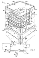
- a fuel cell system is generally referred to by the reference numeral 2.
- the electrolyte is phosphoric acid; however, the invention is not intended to be limited thereon.
- the assembly 2 includes a fuel cell stack 4 with reactant gas manifolds 6a, 6b, 8a, 8b covering each of the four external vertical faces 7a, 7b, 9a, 9b, respectively, of the stack.
- Manifolds 6a, 6b are the fuel (i.e. hydrogen) inlet and outlet manifolds, respectively; and manifolds 8a, 8b are the oxidant (i.e. air) inlet and outlet manifolds respectively.
- the manifolds are held in sealing relationship to the faces of the stack by any suitable means such as by a plurality of bands 10.
- the faces 7a, 7b, 9a, 9b are hereinafter referred to, respectively, as the fuel inlet face, fuel outlet face, oxidant inlet face and oxidant outlet face.
- Each stack 4 is comprised of a plurality of repeating fuel cell units 11.
- the fuel cell units 11 are stacked one atop the other.
- a thick carbon end plate 13 rests on top of the stack.
- a stack may contain only a few cells or several hundreds of cells.
- Each cell may have an active (catalyzed) surface area of only a very few square centimeters up to a square meter or more, depending upon the application for which the system is designed.
- the present invention is particularly suited for use with stacks containing relatively large numbers of fuel cells of fairly large size, since those are the types of systems which are the most difficult to uniformly refill with electrolyte; however, the present invention is not intended to be limited to any particular size cell or stack.
- Each cell unit 11 comprises a fuel cell 12 and a sheet-like separator 14.
- the separator 14 is flat and substantially nonporous to both the reactant gases and the electrolyte.
- Separators may be made by any known method from any material which is compatible with and can withstand the operating environment within the cells.
- the fuel cell electrolyte is phosphoric acid
- these plates are usually made from graphite.
- they may be made by molding, under pressure, a dry mixture of graphite powder and thermosetting resin, the molded parts subsequently being cured and then heat treated to a temperature of at least 2000°C to graphitize the resin.
- the separator is no greater than 1275 ⁇ m thick with 762 to 1016)1m thick being most preferred.
- a suitable separator plate is described in commonly owned U.S. Patent 4,301,222, Emanuelson et al, and is incorporated herein by reference.
- the fuel cells 12 may be similar to those shown and described in commonly owned U.S. Patent No. 4,115,627 which is incorporated herein by reference.
- Each cell 12 includes a thin, sheet-like electrolyte retaining matrix layer 16 sandwiched between a sheet-like anode electrode 20 disposed on one side thereof and a sheet-like cathode electrode 18 disposed on the other side thereof.
- the matrix layer 16 between the anode and cathode electrodes may be 127.5 ⁇ m thick layer of silicon carbide held together by a binder such as polytetra-fluoroethylene, and described in commonly owned U. S. Patent 4,017,664, incorporated herein by reference.
- the anode and cathode electrodes each comprise a relatively thick fibrous gas porous sheet-like substrate having a catalyst layer disposed on a flat surface thereof facing the matrix layer 16.
- the catalyst layer may have a thickness on the order of 50.8 127.5 ⁇ m.
- the substrate thickness may be on the order of about 2032hm thick.
- phosphoric acid cells it is usually a finely divided platinum or platinum alloy supported on carbon particles and bonded together with a fluorocarbon polymer.
- the catalyst is not critical to the present invention.
- Each anode electrode 20 includes a flat face 22 in contact with the lower surface 24 of a separator 14 disposed directly above it.
- a plurality of parallel grooves in the electrode face 22 and perpendicular to the fuel inlet face 7a form, with the separator 14, open chennels 26 which extend through the fuel cell 11 to the opposite face 7b of the stack 4.
- the channels provide gas communication between the fuel inlet manifold 6a and fuel outlet manifold 6b.
- each cathode electrode 18 has a flat face 28 in contact with the upper surface 30 of the separator disposed immediately below it.
- the cathode electrode 18 also includes a plurality of parallel grooves in its face 28 perpendicular to the oxidant inlet face 9a and forming, with the separator 14, open channels 32 extending across the stack 4 from the oxidant inlet manifold 8a to the oxidant outlet manifold 8b.
- the edges of the anode electrodes 20, defining the stack fuel inlet and fuel outlet faces 7a, 7b, respectively, are preferably treated or manufactured such that they act as gas seals which prevent fuel traveling in the channels 26 from leaking into the oxidant manifolds 8a, 8b.
- edges of the cathode electrodes 18 which form a portion of each of the fuel faces 7a, 7b of the stack 4 are also treated or manufactured to act as gas seals to prevent air from leaking from the channels 32 into the fuel manifolds 6a, 6b.
- Commonly owned U.S. Patent 4,269,642 describes one method for forming gas seals along the edges of electrode substrates and is incorporated herein by reference.
- fuel enters the manifold 6a via a conduit 34 and travels through the cells via the channels 26 into the fuel outlet manifold 6b.
- the depleted fuel gas is then carried away from the stack (or recirculated) by means not shown.
- An oxidant such as air, enters the oxidant manifold 8a via the conduit 36 and passes through the cells into the oxidant outlet manifold 8b via the channels 32, and is carried away from the stack by means not shown.
- a horizontal header 40 Disposed within the oxidant inlet manifold 8a near the top of the stack is a horizontal header 40 which feeds a plurality of nozzles 42 each having an opening 44.
- An electrolyte storage tank 46 external of the stack 4, holds phosphoric acid electrolyte (diluted with water to a predetermined concentration, as explained below) for use in replenishing the electrolyte lost from the stack 4 during cell operation.
- a series of conduits provide fluid communication between the tank 46 and the header 40 as further explained hereinbelow.
- the stack is first taken off line.
- a valve 48 in a conduit 49 is opened which permits electrolyte to flow from the tank 46 into a conduit 50.
- the electrolyte is pumped through the conduit 50 to the header 40 by a pump 52.
- a filter 54 disposed within the conduit 50 assures that the electrolyte added to the stack 4 is clean.
- the nozzles 42 direct streams 53 of the dilute electrolyte against the surface 9a.
- the number and location of the nozzles 42 and the size of their outlets 44 are designed to create a substantially continuous vertically falling film 54 of electrolyte over the entire surface 9a.
- This film is, of course, in contact with the edges of the fuel cell components, such as the edges of the matrices 16, the anode electrodes 20 and the cathode electrodes 18. These components are porous, and the electrolyte which comes into contact with their edges is drawn into them and across the cells by capillary action.
- the cathode electrodes may absorb electrolyte faster than the anode electrodes since the edges of the anode electrodes along the oxidant inlet face 9a of the stack will normally be less porous than the cathode electrode edges due to the presence of the gas seal discussed above. Electrolyte which is not absorbed by the stack runs off the stack face to the bottom of the oxidant inlet manifold 8a.
- a conduit 60 attached to the bottom of the manifold 8a feeds that excess electrolyte back into the tank 46 for recirculation.
- Electrolyte is added and recirculated until a steady state is reached wherein both the anode and cathode electrodes and the matrix layers of every cell in the stack are completely saturated with electrolyte at the same concentration.
- the valve 48 is then closed and a valve 62 is opened to drain electrolyte from the circulating system and from the manifold 8a.
- the volume of circulated electrolyte i.e. the amount in the tank 46
- the volume of circulated electrolyte is preferably large relative to the amount of electrolyte remaining in the stack just prior to refilling in order that the concentration of electrolyte in the fully saturated stack at steady state will be substantially the concentration of the electrolyte in the storage tank at the onset of the refilling operation. This eliminates the need to estimate the amount and concentration of electrolyte in the stack at the beginning of the refilling operation.
- the total volume of electrolyte held by the stack when fully saturated This volume will depend upon whether there is electrolyte within the reactant gas channels 32 after steady state has been reached. Unless the channels are completely empty or completely filled, it will not be possible to determine the total volume of electrolyte in the stack. Whether or not the gas channels will become filled may depend upon several factors. The size of the channels is one factor. Large channels will tend to remain empty while small channels will tend to fill and hold electrolyte by capillary action.
- the liquid volume in each cell must be reduced to a proper level for cell operation, and the electrolyte must also be brought to a suitable operating concentration.
- the stack is heated to a preselected temperature, which is preferably, but not necessarily, the temperature at which the stack normally operates. This may be done by various means. For example, the process could be conducted within an oven in which the stack is disposed; or heaters could be strapped onto the stack.
- the stack's own internal cooling system is used to heat the stack, such as by conducting hot liquid or gas through cooling tubes which pass through the stack at various locations. (Stack cooling systems are shown and described in commonly owned U.S.
- a moist gas such as nitrogen or air, having a known dew point, is passed through the fuel channels 26 and/or oxidant channels 32 (if they are empty).
- water evaporates into the moist gas stream.
- the process is continued until a steady state is reached and no further water evaporates from the stack. This occurs when the vapor pressure of the water in the gas equals the vapor pressure of the water in the cells. Steady state conditions will determine the final volume of liquid in the stack and the concentration of electrolyte remaining in the stack.
- a phosphoric acid fuel cell stack which operates at a nominal temperature of 204 0 C was heated from room temperature to about 132 0 C at a rate of 2 O C every 15 minutes.
- the initial concentration of acid in the fully saturated stack was 40% by weight.
- the moist gas was then replaced by hydrogen.
- the temperature of the stack was further increased at a rate of 8.5 to 11°C every 15 minutes until a temperature of 20 4 ° C was reached. Upon reaching this temperature, the stack was put on line (i.e. to produce power). Within a short time (about 30 to 60 minutes) steady state was reached and the acid concentration was at the desired level of about 100%.
- electrolyte is deposited only on one side or face of the stack. It should be apparent that the same procedure may be utilized simultaneously on other sides of the stack and will speed the refilling process. Furthermore, it is not intended that the invention be limited to depositing electrolyte on the face of the stack by means of a plurality of nozzles fed by a common header which create streams of electrolyte against the surface only near the top of the stack. Any means for depositing the electrolyte in a manner which results in substantially the entire face of the stack being maintained continuously wet (such as with a film of electrolyte which moves down the face) for a sufficiently long period of time to fully saturate the stack to a steady state condition may be used.
- Fig. 4 shows an embodiment of the present invention described and claimed in commonly owned U.S. Patent Application Serial No. (Our Docket No. C-602) filed on even date herewith, entitled “Method and Apparatus for Adding Electrolyte to a Fuel Cell Stack” by V. Congdon and J. English, incorporated herein by reference.
- the separator plates 14 are extended outwardly of the oxidant inlet face 9a to form tabs or shelves 102, the uppermost tab being designated by the reference numeral 102.
- the nozzles 42 have been replaced by holes 100 in the bottom of the header 40 through which the electrolyte drips onto the uppermost tab 102'.
- Some of the electrolyte cascades over the edges of the tab 102' and down the vertical face of the stack to the next succeeding tab, and so forth, until a continuous flow of electrolyte is running over the tabs down the face of the stack.
- the tabs help distribute the electrolyte uniformly over the width and height of the face 9a of the stack.
- Some of the electrolyte tends to accumulate along the back edges of the tabs. This accumulated electrolyte rests on the tabs against the stack face thereby providing a "reservoir" of electrolyte which is continuously absorbed into the edges of the cell components immediately above each tab. This speeds the refilling process.
- the reservoir is continuously replenished as electrolyte is deposited on the tabs.
Landscapes
- Life Sciences & Earth Sciences (AREA)
- Engineering & Computer Science (AREA)
- Manufacturing & Machinery (AREA)
- Sustainable Development (AREA)
- Sustainable Energy (AREA)
- Chemical & Material Sciences (AREA)
- Chemical Kinetics & Catalysis (AREA)
- Electrochemistry (AREA)
- General Chemical & Material Sciences (AREA)
- Fuel Cell (AREA)
Applications Claiming Priority (2)
| Application Number | Priority Date | Filing Date | Title |
|---|---|---|---|
| US06/638,337 US4612262A (en) | 1984-08-06 | 1984-08-06 | Process for adding electrolyte to a fuel cell stack |
| US638337 | 1991-01-07 |
Publications (3)
| Publication Number | Publication Date |
|---|---|
| EP0171347A2 true EP0171347A2 (fr) | 1986-02-12 |
| EP0171347A3 EP0171347A3 (en) | 1986-08-13 |
| EP0171347B1 EP0171347B1 (fr) | 1989-05-10 |
Family
ID=24559626
Family Applications (1)
| Application Number | Title | Priority Date | Filing Date |
|---|---|---|---|
| EP85630119A Expired EP0171347B1 (fr) | 1984-08-06 | 1985-08-01 | Procédé pour ajouter de l'électrolyte à une batterie de piles à combustible |
Country Status (7)
| Country | Link |
|---|---|
| US (1) | US4612262A (fr) |
| EP (1) | EP0171347B1 (fr) |
| JP (1) | JPS6147074A (fr) |
| BR (1) | BR8503664A (fr) |
| CA (1) | CA1246139A (fr) |
| DE (2) | DE3570155D1 (fr) |
| ZA (1) | ZA855888B (fr) |
Families Citing this family (7)
| Publication number | Priority date | Publication date | Assignee | Title |
|---|---|---|---|---|
| JPH0821398B2 (ja) * | 1987-12-02 | 1996-03-04 | 三菱電機株式会社 | 積層形燃料電池 |
| US4978591A (en) * | 1989-09-11 | 1990-12-18 | The United States Of America As Represented By The United States Department Of Energy | Corrosion free phosphoric acid fuel cell |
| US20020197517A1 (en) * | 2001-06-22 | 2002-12-26 | Mackelvie Winston | Fuel cell enhancement process |
| GB201001972D0 (en) * | 2010-02-08 | 2010-03-24 | Afc Energy Plc | Cell stack system |
| KR20140126718A (ko) | 2012-01-26 | 2014-10-31 | 두산 퓨얼 셀 아메리카, 인크. | 연료전지 내의 전해질 생성 |
| DE102012208222A1 (de) * | 2012-05-16 | 2013-11-21 | Evonik Litarion Gmbh | Modellbasiertes Elektrolyt-Befüllverfahren |
| TWI527300B (zh) * | 2015-02-13 | 2016-03-21 | Taiwan Carbon Nano Technology Corp | Hierarchical arrangement of parallel seawater batteries |
Citations (4)
| Publication number | Priority date | Publication date | Assignee | Title |
|---|---|---|---|---|
| JPS58165258A (ja) * | 1982-03-26 | 1983-09-30 | Fuji Electric Co Ltd | 燃料電池のマトリックスへの電解液含浸方法 |
| JPS58165268A (ja) * | 1982-03-26 | 1983-09-30 | Fuji Electric Co Ltd | 燃料電池のマトリックスへの電解液含浸方法 |
| EP0106605A1 (fr) * | 1982-09-30 | 1984-04-25 | Engelhard Corporation | Pile à combustible à matrice diélectrolyte à porosité multiple et système d'admission de l'électrolyte |
| EP0107396A1 (fr) * | 1982-09-30 | 1984-05-02 | Engelhard Corporation | Système d'admission d'électrolyte à des piles à combustible |
Family Cites Families (8)
| Publication number | Priority date | Publication date | Assignee | Title |
|---|---|---|---|---|
| BE868387A (nl) * | 1977-06-29 | 1978-12-27 | Electrochem Energieconversie | Batterij-eenheid, bevattende een of meer brandstofcellenblokken |
| US4185145A (en) * | 1978-09-11 | 1980-01-22 | United Technologies Corporation | Fuel cell electrolyte reservoir layer and method for making |
| JPS5792759A (en) * | 1980-12-01 | 1982-06-09 | Sanyo Electric Co Ltd | Liquid pouring method of matrix type fuel cell |
| US4463068A (en) * | 1982-09-30 | 1984-07-31 | Engelhard Corporation | Fuel cell and system for supplying electrolyte thereto with wick feed |
| US4450212A (en) * | 1982-09-30 | 1984-05-22 | Engelhard Corporation | Edge seal for a porous gas distribution plate of a fuel cell |
| US4463066A (en) * | 1982-09-30 | 1984-07-31 | Engelhard Corporation | Fuel cell and system for supplying electrolyte thereto |
| US4467019A (en) * | 1982-09-30 | 1984-08-21 | Engelhard Corporation | Fuel cell with electrolyte feed system |
| US4487157A (en) * | 1983-11-07 | 1984-12-11 | Hazelett Strip-Casting Corporation | Machine for producing insulative and protective coatings on endless flexible metallic belts of continuous casting machines |
-
1984
- 1984-08-06 US US06/638,337 patent/US4612262A/en not_active Expired - Fee Related
-
1985
- 1985-06-27 CA CA000485581A patent/CA1246139A/fr not_active Expired
- 1985-08-01 DE DE8585630119T patent/DE3570155D1/de not_active Expired
- 1985-08-01 DE DE198585630119T patent/DE171347T1/de active Pending
- 1985-08-01 EP EP85630119A patent/EP0171347B1/fr not_active Expired
- 1985-08-02 BR BR8503664A patent/BR8503664A/pt unknown
- 1985-08-05 ZA ZA855888A patent/ZA855888B/xx unknown
- 1985-08-06 JP JP60173072A patent/JPS6147074A/ja active Pending
Patent Citations (4)
| Publication number | Priority date | Publication date | Assignee | Title |
|---|---|---|---|---|
| JPS58165258A (ja) * | 1982-03-26 | 1983-09-30 | Fuji Electric Co Ltd | 燃料電池のマトリックスへの電解液含浸方法 |
| JPS58165268A (ja) * | 1982-03-26 | 1983-09-30 | Fuji Electric Co Ltd | 燃料電池のマトリックスへの電解液含浸方法 |
| EP0106605A1 (fr) * | 1982-09-30 | 1984-04-25 | Engelhard Corporation | Pile à combustible à matrice diélectrolyte à porosité multiple et système d'admission de l'électrolyte |
| EP0107396A1 (fr) * | 1982-09-30 | 1984-05-02 | Engelhard Corporation | Système d'admission d'électrolyte à des piles à combustible |
Non-Patent Citations (2)
| Title |
|---|
| PATENTS ABSTRACTS OF JAPAN, vol. 7, no. 288 (E-218) [1433], 22nd December 1983; & JP - A - 58 165 258 (FUJI DENKI SEIZO K.K.) 30-09-1983 * |
| PATENTS ABSTRACTS OF JAPAN, vol. 7, no. 288 (E-218) [1433], 22nd December 1983; & JP - A - 58 165 268 (FUJI DENKI SEIZO K.K.) 30-09-1983 * |
Also Published As
| Publication number | Publication date |
|---|---|
| EP0171347A3 (en) | 1986-08-13 |
| US4612262A (en) | 1986-09-16 |
| DE171347T1 (de) | 1986-06-12 |
| ZA855888B (en) | 1986-04-30 |
| CA1246139A (fr) | 1988-12-06 |
| EP0171347B1 (fr) | 1989-05-10 |
| DE3570155D1 (en) | 1989-06-15 |
| JPS6147074A (ja) | 1986-03-07 |
| BR8503664A (pt) | 1986-05-06 |
Similar Documents
| Publication | Publication Date | Title |
|---|---|---|
| US4769297A (en) | Solid polymer electrolyte fuel cell stack water management system | |
| US7153605B2 (en) | Fuel cell cooled by latent heat of water evaporation | |
| JP3596332B2 (ja) | 積層型燃料電池の運転方法、積層型燃料電池及び積層型燃料電池システム | |
| JP3203150B2 (ja) | 固体高分子型燃料電池及び固体高分子型燃料電池システム | |
| US6376110B1 (en) | Method for regulating membrane moisture of a polymer electrolyte fuel cell, and a polymer electrolyte fuel cell | |
| JP5174471B2 (ja) | Pem燃料電池スタックのヘッダ用の水分除去チャネル | |
| US6723461B2 (en) | Water management system for fuel cell | |
| JPS6130385B2 (fr) | ||
| JPH06231793A (ja) | 固体高分子電解質型燃料電池 | |
| EP1952471B1 (fr) | Pile a combustible pem dotee d'une chambre de chargement | |
| WO2006071580A2 (fr) | Piles a combustible refroidies par evaporation au moyen de gaz reactifs et procede antigivrage | |
| JP2006339145A (ja) | 燃料電池セパレータ板コーティング | |
| US4463067A (en) | Fuel cell and system for supplying electrolyte thereto utilizing cascade feed | |
| EP0171346B1 (fr) | Méthode et dispositif pour ajouter de l'électrolyte à une batterie de piles à combustible | |
| US4612262A (en) | Process for adding electrolyte to a fuel cell stack | |
| JPS61227370A (ja) | 燃料電池集合体 | |
| EP0107396B1 (fr) | Système d'admission d'électrolyte à des piles à combustible | |
| JPH07320753A (ja) | 固体高分子電解質膜型燃料電池 | |
| WO2024015648A1 (fr) | Plaque bipolaire à quatre fluides pour pile à combustible | |
| CN106133972A (zh) | 用于延长ht‑pem燃料电池的使用寿命的设备和方法 | |
| WO1994015377A1 (fr) | Dispositif a pile a combustible a membrane d'echange de protons, et a plaques de separation pour le transfert de l'eau | |
| US20040058206A1 (en) | Method for improving the water balance of fuel cells | |
| EP0262961B1 (fr) | Cellule à combustible ayant un ensemble de matrice contenant l'électrolyte | |
| EP0181134B1 (fr) | Batterie de piles à combustible comportant des moyens de récupération de l'électrolyte | |
| KR102604253B1 (ko) | 바이폴라 플레이트를 갖는 연료 전지 스택, 및 연료 전지 시스템 |
Legal Events
| Date | Code | Title | Description |
|---|---|---|---|
| PUAI | Public reference made under article 153(3) epc to a published international application that has entered the european phase |
Free format text: ORIGINAL CODE: 0009012 |
|
| AK | Designated contracting states |
Designated state(s): BE DE FR GB IT NL |
|
| TCNL | Nl: translation of patent claims filed | ||
| EL | Fr: translation of claims filed | ||
| ITCL | It: translation for ep claims filed |
Representative=s name: RICCARDI SERGIO & CO. |
|
| DET | De: translation of patent claims | ||
| PUAL | Search report despatched |
Free format text: ORIGINAL CODE: 0009013 |
|
| AK | Designated contracting states |
Kind code of ref document: A3 Designated state(s): BE DE FR GB IT NL |
|
| 17P | Request for examination filed |
Effective date: 19870129 |
|
| 17Q | First examination report despatched |
Effective date: 19880115 |
|
| GRAA | (expected) grant |
Free format text: ORIGINAL CODE: 0009210 |
|
| AK | Designated contracting states |
Kind code of ref document: B1 Designated state(s): BE DE FR GB IT NL |
|
| REF | Corresponds to: |
Ref document number: 3570155 Country of ref document: DE Date of ref document: 19890615 |
|
| PGFP | Annual fee paid to national office [announced via postgrant information from national office to epo] |
Ref country code: FR Payment date: 19890710 Year of fee payment: 5 |
|
| PGFP | Annual fee paid to national office [announced via postgrant information from national office to epo] |
Ref country code: BE Payment date: 19890727 Year of fee payment: 5 |
|
| PGFP | Annual fee paid to national office [announced via postgrant information from national office to epo] |
Ref country code: GB Payment date: 19890731 Year of fee payment: 5 Ref country code: DE Payment date: 19890731 Year of fee payment: 5 |
|
| ET | Fr: translation filed | ||
| ITF | It: translation for a ep patent filed |
Owner name: UFFICIO BREVETTI RICCARDI & C. |
|
| ITTA | It: last paid annual fee | ||
| PGFP | Annual fee paid to national office [announced via postgrant information from national office to epo] |
Ref country code: NL Payment date: 19890831 Year of fee payment: 5 |
|
| PLBE | No opposition filed within time limit |
Free format text: ORIGINAL CODE: 0009261 |
|
| STAA | Information on the status of an ep patent application or granted ep patent |
Free format text: STATUS: NO OPPOSITION FILED WITHIN TIME LIMIT |
|
| 26N | No opposition filed | ||
| PG25 | Lapsed in a contracting state [announced via postgrant information from national office to epo] |
Ref country code: GB Effective date: 19900801 |
|
| PG25 | Lapsed in a contracting state [announced via postgrant information from national office to epo] |
Ref country code: BE Effective date: 19900831 |
|
| BERE | Be: lapsed |
Owner name: UNITED TECHNOLOGIES CORP. Effective date: 19900831 |
|
| PG25 | Lapsed in a contracting state [announced via postgrant information from national office to epo] |
Ref country code: NL Effective date: 19910301 |
|
| GBPC | Gb: european patent ceased through non-payment of renewal fee | ||
| NLV4 | Nl: lapsed or anulled due to non-payment of the annual fee | ||
| PG25 | Lapsed in a contracting state [announced via postgrant information from national office to epo] |
Ref country code: FR Effective date: 19910430 |
|
| PG25 | Lapsed in a contracting state [announced via postgrant information from national office to epo] |
Ref country code: DE Effective date: 19910501 |
|
| REG | Reference to a national code |
Ref country code: FR Ref legal event code: ST |