EP0170271A2 - Elektronische Registrierkasse - Google Patents
Elektronische Registrierkasse Download PDFInfo
- Publication number
- EP0170271A2 EP0170271A2 EP85109607A EP85109607A EP0170271A2 EP 0170271 A2 EP0170271 A2 EP 0170271A2 EP 85109607 A EP85109607 A EP 85109607A EP 85109607 A EP85109607 A EP 85109607A EP 0170271 A2 EP0170271 A2 EP 0170271A2
- Authority
- EP
- European Patent Office
- Prior art keywords
- bar code
- department
- commodity
- key
- registered
- Prior art date
- Legal status (The legal status is an assumption and is not a legal conclusion. Google has not performed a legal analysis and makes no representation as to the accuracy of the status listed.)
- Withdrawn
Links
Images


Classifications
-
- G—PHYSICS
- G07—CHECKING-DEVICES
- G07G—REGISTERING THE RECEIPT OF CASH, VALUABLES, OR TOKENS
- G07G1/00—Cash registers
- G07G1/12—Cash registers electronically operated
- G07G1/14—Systems including one or more distant stations co-operating with a central processing unit
- G07G1/145—PLU-management
-
- G—PHYSICS
- G07—CHECKING-DEVICES
- G07G—REGISTERING THE RECEIPT OF CASH, VALUABLES, OR TOKENS
- G07G1/00—Cash registers
- G07G1/12—Cash registers electronically operated
Definitions
- the present invention relates to an electronic cash register (ECR). More particularly, the present invention relates to an electronic cash register in which a bar code attached to a commodity is read out by a scanner so that the data concerning the commodity can be registered.
- ECR electronic cash register
- bar code there is one kind of bar code, which is a so-called source marking which is pointed in advance in a package for a commodity by a maker who produces the commodity and there is another kind of bar code, which is a so-called instore marking, in which a store selling commodities prints a bar code on a label which is attached to a commodity.
- the bar code of the source marking includes only a commodity code of the commodity as recorded and the bar code of the instore marking includes an amount data of a commodity as coded and recorded, as well as the commodity code.
- a PLU file is actually provided in most of conventional electronic cash registers, so that when a bar code of instore marking is read out, the PLU file is searched based on the commodity code recorded in the bar code as read out so that the department-to-be-registered can be identified.
- PLU file used in an electronic cash register requires a large scale capacity of memory.
- the amount data of commodities stored in the PLU file must be changed each time the amount of the commodities varies. For this reason, it is usual that PLU file is not required for a store requiring only bar codes of instore marking to be read out.
- a primary object of the present invention is to provide an electronic cash register which can register data concerning commodities by reading out the bar code of an instore marking, without needing any PLU file.
- a bar code attached to a commodity is read out by a bar code reading means and, based on an identification code contained in the bar code, representing a kind of the bar code,
- department-of-destination-to-be-registered storing means is searched, so that a department number of destination-to-be-registered corresponding to the identification code stored in advance is determined.
- An amount data of the commodity recorded in the bar code as read out is registered in each department storing region of department storing means corresponding to the determined department.
- the kind of bar code of instore marking recording a commodity code and an amount data is determined so that the department of destination-to-be-registered of that commodity can be searched, and hence, the data concerning the commodity can be registered in the corresponding department storing region, without referring to a PLU file, after reading out the bar code. Accordingly, in a situation where only a bar code of instore marking is read out and registered, there is no need to provide a PLU file of a large scale memory and hence a cost of an electronic cash register can be reduced. In addition, even if a price of a commodity changes, there is no need to alter the amount data in the PLU file at each time.
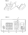
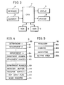
- Fig. 1 is a perspective view of one embodiment of the present invention and Fig. 2 is a key arrangement of a keyboard included in an electronic cash register shown in Fig. 1.
- a scanner 2 a bar code reading means, connected to an electronic cash register main body 1 through a cable 3.
- the scanner 2 reads out a bar code recorded in a commodity or a bar code recorded in a label attached to a commodity.
- the electronic cash register main body 1 is provided with a keyboard 4 on a vertical operating surface, and with a display 5 and a printer 6 on a vertical operating surface thereof.
- the keyboard 4 is provided with a mode selection switch 41, department keys 42, a ten-key 43 and function keys 44.
- the mode selection switch 41 selects one of a program mode (P), a power supply-off mode (OFF), a register mode (R), an inspection mode (X) and an adjustment mode (Z).
- the department keys 42 designate a department number of a commodity to be registered.
- the ten-key 43 is adapted to input the data concerning the number of commodities.
- the ten-key 43 includes an X-key 431.
- the X-key 431 is adapted to specify that the numerical data inputted from the ten-key 43 is the number of commodities.
- the function keys 44 are operated for providing various kinds of processing instructions and comprise a sub-total key 441 and a cash total/deposit key 442.
- the sub-total key 441 is operated when an operation of the total data of the commodities registered so far is instructed, and the cash total/deposit key 442 is operated or depressed when an operation of total of amount data concerning all of the commodities that a customer purchased is instructed or when operation for calculating a change is instructed.
- the sub-total key 441 and the cash total/deposit key 442 are also operated or depressed when the department of destination to be registered, as described subsequently, is set.
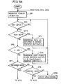
- Fig. 3 is a schematic block diagram of one embodiment of the present invention and Figs. 4 and 5 are diagrams showing the data stored in a random access memory 9 shown in Fig. 3.
- the scanner 2 the keyboard 4, the display 5 and the printer 6 as shown in Fig. 1, are connected to a central processing unit 7.
- a read only memory (ROM) 8 and a random access memory (RAM) 9 are connected in association with the cental processing unit 7.
- the read only memory 8 stores in advance a program based on a flow diagram shown in Figs. 9A through 9D described subsequently.
- the random access memory 9 includes storage areas 91, 92, ... 9n, 100, 101, ... 109, and 111 through 114 for storing each kind of data, as shown in Figs. 4 and 5.
- the storage areas 91, 92, ... 9n constitute a department file 90 as department storing means and each of the areas includes, as shown in Fig. 6, a totalizer 901, a counter 902, a descriptor area 903 and a setting area 904.
- the totalizer 901 stores the amount sold for each department
- the counter 902 is an area for storing accumulatively the number of registering commodities for each department
- the descriptor area 903 is an area for storing a descriptor for each department
- the setting area 904 is an area for storing a status, such as presence or absence of tax, and presence or absence of authorization printing.
- the storage areas 100, 101, .... 109 constitutes department-number-of-destination-to-be-registered storing means which stores department number of destination to be registered, corresponding to the kind of the bar code.
- the storage areas 111, 112 are used as a register buffer for temporarily storing numerical data inputted from the ten-key 43.
- the storage areas 113 stores a register flag indicating an operation of the ten-key 43 and flag F1 indicating an operation of the X-key 431.
- the storage area 114 is used as a work register for temporarily storing the data necessary for processing by the central processing unit 7.
- Fig. 6 is a diagram showing bar codes.
- the bar code shown in Fig. 6 is a type of an instore marking as described in the foregoing, the instore marking including UPC TYPE II and EAN 13.
- the EAN 13 includes 21 through 29 recorded in the top of the code indicating each of bar codes and also includes nine kinds of EAN 13 FLAG 21 through EAN 13 FLAG 29 as used. In case where a label is attached to each commodity in an instore marking, it may be attached corresponding to any one of these format types for each department.
- X 1 through X 5 of the UPC TYPE II and X 1 through X 4 of the EAN 13 represent commodity code and P 1 through P 4 of the UPC TYPE II and P 1 through P 5 of the EAN 13 represent amount data.
- C/P is a check digit for amount data and C is a check digit for the whole bar code.
- Fig. 7A is a diagram showing a procedure of key operation when the department of destination to be registered is set
- Fig. 7B is a diagram showing a procedure of key operation for registering
- Fig. 8A is an example of a printed receipt when the department of destination to be registered is set
- Fig. BB is an example of a printed receipt for registering.
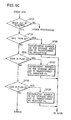
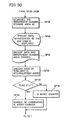
- Figs. 9A through 9D are flow diagrams for explaining a specific operation of one embodiment of the present invention.
- a department number of destination to be registered is set in the storage areas 100, 101, ... 109. More particularly, an operator operates a mode selection switch 41 for selecting a preset mode. Then, in accordance with a procedure of key operation shown in Fig. 7A, a number representing the kind of bar code is inputted from the ten-key 43. That is, if and when a kind of bar code is of the UPC TYPE II, "0" is inputted, and if the kind of bar code is of the ENA 13 FLAG 21, "1" is inputted, if EAN 13 FLAG 22, "2", ....
- the X-key 431 is operated so that it can be specified that the numerical data inputted from the ten-key 43 is the kind of the bar code. Thereafter, the operator provides, by using the ten-key 43, the numerical data showing a department number and again operates the X-key 431 so that it can be specified that the inputted numerical data is a department number. In such a way, the kind of bar code and the department number are inputted and when the next department number of destination to be registered is set, a sub-total key 41 is operated. After completion of all of the department numbers of destination to be registered, a cash total/deposit key 442 is operated.
- the central processing unit 7 sets such department number as inputted in the storage areas 100, 101, ... 109. More particularly, the central processing unit 7 clears the register flag and flag F1 in the step SP1. In the step SP2, the central processing unit 7 waits until any key input is applied and if and when it is determined that any key input is applied, the program proceed to the step SP3. In the step SP3, it is determined whether numerical data from the ten-key 43 is applied or not, and if applied, in the step SP4, the numerical data as inputted is stored in the register buffer 111.
- step SP5 If and when the X-key 431 is operated for the purpose of specifying that the numerical data inputted from the ten-key 43 is the kind of bar code, in the step SP5, it is determined whether the X-key 431 is operated and if operated, in the step SP6, the numerical data stored in the register buffer 111 is transferred to the register buffer 112. As a result, in the register buffer 112, the identification code representing the kind of the bar code comes to be stored.
- an operator After inputting the numerical data representative of the kind of bar code, an operator inputs a department number by using a ten-key 43, and then, in the step SP2, the central processing unit 7 determines that any key operation was made, and if and when it is determined in the step SP3, that the numerical data from the ten-key 43 is inputted, the inputted numerical data is stored in the register buffer 111 in the step-SP4.
- the operator operates the X-key 431 for the purpose of specifying that the numerical data inputted from the ten-key 43 is a department number, and then in the step SP5, the central processing unit 7 determines that the X-key 431 was operated and the numerical data stored in the register buffer 111 is transferred to the register buffer 112.
- the identification code representing the kind of the bar code and the department number corresponding to the bar code come to be stored.
- the program again returns to the step SP2 in which any key operation is determined and, if and when no ten-key 43 is operated in the step SP3, and no X-key 431 is operated in the step SP5, the mode set by the mode selection switch 41 is determined in the steps SP7 and SP8. If and when the program mode is determined in the step SP7, the program proceeds to the programming processing operation of the step SP10 and the steps subsequent thereto. If and when it is determined that the mode is not a program mode in the step SP7, it is determined whether the mode is a register mode or not in the step SP8. If it is a register mode, the program proceed to the registering operation defined in the step SP22 and the steps subsequent thereto, and if it is not a register mode, other processing is made in the step SP80.
- the central processsing unit 7 determines whether the sub-total key 441 is operated or not in the step SP10. If and when it is determined that the sub-total key 441 is operated, it is determined whether the register flag is set in the step SP11. Since the register flag has been set in the storage area 113 when the ten-key 43 is operated, the central processsing unit 7 makes a decision, depending on the fact that the register flag is set in the storage area 113 or not. If the register flag is set, an error processing is made.
- the central processing unit 7 determines whether the flag F1 is set in the storage area 113 or not in the step SP12.
- the flag Fl is set when the X-key 431 is operated. If and when the flag F1 is set, it is determined in the step SP13, whether the numerical value representing the kind of the bar code stored in the register buffer 112 is "0" or not. If it is "0", which means that the kind of the bar code is of the UPC TYPE II, the department number stored in the register buffer 112 is transferred to the department storage area 100 in the step SP16.
- step SP14 determines whether the numerical value representing the kind of the bar code stored in the register buffer 112 is "1" or not. If and when "1" is stored in the register buffer 112, the department number stored in the register buffer 112 is transferred to the storage area 101 in the step SP17. Similarly, based on the numerical value representing the kind of the bar code stored in the register buffer 112, department numbers as sequentially inputted are set in the storage area 109.
- the central processing unit 7 After completion of setting department numbers in the storage area 109, the central processing unit 7 applies to the printer 6 the data as set respectively in the storage areas 100, 101, ... 109 in the step SP21, so that the printed form as shown in Fig. 8A can be obtained. Finally, if and when the operator depresses the cash total/deposit key 442, it is determined in the step SP19 whether the cash total/deposit key 442 is operated or not and if and when it is determined that such key 442 is operated, the character "end print" is printed by the printer 6 in the step SP20.
- register mode an operator selects a register mode through the mode selection switch 41 and the bar code attached to the commodity the customer purchased is read out by the scanner 2.
- step SP8 it is determined whether the register mode is set or not and if set, it is determined whether such registration is made by the scanner 2 or not in the step SP22. If it is determined that such registration is made by the scanner 2, and then it is determined whether the bar code as read out is of the UPC TYPE II or not in the step SP23. If it is the UPC TYPE I1 bar code, in the step SP26, the department number stored in the department number storage area 100 is stored in the register 114. If and when the bar code as read out is not UPC TYPE II, it is determined whether it is a bar code of EAN 13 FLAG 21 in the step SP24.
- step SP27 If it is a bar code of EAN 13 FLAG 21, in the step SP27, the department number stored in the department number storage area 101 is stored in the register 114. Subsequently, the similar processing is made and if and when in the step SP25, it is a bar code of EAN 13 FLAG 29, the department number stored in the department number storage area 109 is stored in the register 114 in the step SP28.
- the central processing unit 7 searches the department number storage area 90 based on the department number stored in the register 114. Then, in the step SP30, amount data represented by the bar code is displayed in the display 5. Furthermore, in the step SP31, the descriptor of the department is read out from the storage area of the corresponding department and descriptor, the amount data and the department number are printed by the printer 6 in a manner as shown in Fig. 8B. In addition, in the step SP32, the amount data of the totalizer of the corresponding department number is accumulatively added. Furthermore, in the step SP33, the central processing unit 7 determines whether the flag Fl is set or not.
Landscapes
- Physics & Mathematics (AREA)
- General Physics & Mathematics (AREA)
- Engineering & Computer Science (AREA)
- Computer Networks & Wireless Communication (AREA)
- Cash Registers Or Receiving Machines (AREA)
Applications Claiming Priority (2)
| Application Number | Priority Date | Filing Date | Title |
|---|---|---|---|
| JP162604/84 | 1984-07-31 | ||
| JP16260484A JPS6140692A (ja) | 1984-07-31 | 1984-07-31 | 電子式キヤツシユレジスタ |
Publications (2)
| Publication Number | Publication Date |
|---|---|
| EP0170271A2 true EP0170271A2 (de) | 1986-02-05 |
| EP0170271A3 EP0170271A3 (de) | 1988-03-16 |
Family
ID=15757747
Family Applications (1)
| Application Number | Title | Priority Date | Filing Date |
|---|---|---|---|
| EP85109607A Withdrawn EP0170271A3 (de) | 1984-07-31 | 1985-07-31 | Elektronische Registrierkasse |
Country Status (2)
| Country | Link |
|---|---|
| EP (1) | EP0170271A3 (de) |
| JP (1) | JPS6140692A (de) |
Cited By (4)
| Publication number | Priority date | Publication date | Assignee | Title |
|---|---|---|---|---|
| EP0234402A3 (en) * | 1986-02-10 | 1988-11-17 | Omron Tateisi Electronics Co. | Electronic cash register |
| EP0261650A3 (de) * | 1986-09-22 | 1989-10-25 | Omron Tateisi Electronics Co. | Elektronisches Registrierkassensystem mit kürzerer Zugangszeit zum Preisespeicher |
| US5710416A (en) * | 1995-10-05 | 1998-01-20 | Ncr Corporation | Price verifier |
| JP2014222505A (ja) * | 2014-06-17 | 2014-11-27 | カシオ計算機株式会社 | 情報処理装置及びプログラム |
Families Citing this family (1)
| Publication number | Priority date | Publication date | Assignee | Title |
|---|---|---|---|---|
| US7399098B2 (en) | 2003-04-18 | 2008-07-15 | Matsushita Electric Industrial Co., Ltd. | Illuminating apparatus for operating section |
Family Cites Families (5)
| Publication number | Priority date | Publication date | Assignee | Title |
|---|---|---|---|---|
| US3181124A (en) * | 1962-04-05 | 1965-04-27 | David G Hammel | Data processing system |
| JPS5578371A (en) * | 1978-12-08 | 1980-06-12 | Tokyo Electric Co Ltd | Electronic cash register |
| DE3147274A1 (de) * | 1981-11-28 | 1983-06-09 | Maatschappij van Berkel's, Patent N.V., Rotterdam | Anlage mit mehreren unabhaengigen ladenwaagen |
| JPS59121466A (ja) * | 1982-12-27 | 1984-07-13 | Sharp Corp | 金銭登録機 |
| JPS59220875A (ja) * | 1983-05-27 | 1984-12-12 | Sharp Corp | 電子式キヤツシユレジスタ |
-
1984
- 1984-07-31 JP JP16260484A patent/JPS6140692A/ja active Granted
-
1985
- 1985-07-31 EP EP85109607A patent/EP0170271A3/de not_active Withdrawn
Cited By (4)
| Publication number | Priority date | Publication date | Assignee | Title |
|---|---|---|---|---|
| EP0234402A3 (en) * | 1986-02-10 | 1988-11-17 | Omron Tateisi Electronics Co. | Electronic cash register |
| EP0261650A3 (de) * | 1986-09-22 | 1989-10-25 | Omron Tateisi Electronics Co. | Elektronisches Registrierkassensystem mit kürzerer Zugangszeit zum Preisespeicher |
| US5710416A (en) * | 1995-10-05 | 1998-01-20 | Ncr Corporation | Price verifier |
| JP2014222505A (ja) * | 2014-06-17 | 2014-11-27 | カシオ計算機株式会社 | 情報処理装置及びプログラム |
Also Published As
| Publication number | Publication date |
|---|---|
| JPH0228199B2 (de) | 1990-06-21 |
| JPS6140692A (ja) | 1986-02-26 |
| EP0170271A3 (de) | 1988-03-16 |
Similar Documents
| Publication | Publication Date | Title |
|---|---|---|
| JP2501115B2 (ja) | 電子式キャッシュレジスタ | |
| EP0322442B1 (de) | Verfahren zur verarbeitung von daten bezüglich abgekaufter waren | |
| US5202984A (en) | Apparatus and method for updating transaction file | |
| US4493037A (en) | Retail terminal | |
| KR920004437B1 (ko) | 금전등록기의 거래선 관리방법 | |
| EP0028127A1 (de) | Elektronische Registrierkasse | |
| US4502119A (en) | Electronic register | |
| US5742039A (en) | Commodity management system | |
| WO2003053702A1 (en) | Commodity information printing apparatus and commodity label attachment | |
| EP0170271A2 (de) | Elektronische Registrierkasse | |
| EP0239982A2 (de) | Dateneingabevorrichtung | |
| US4752875A (en) | Electronic cash register with a specialized data capturing function | |
| US4879649A (en) | Transaction processing apparatus having PLU function | |
| US4742521A (en) | Bar cord information input confirming method | |
| US4949258A (en) | Transaction processor which derives a commodity code from an article code and stores sales of data of both | |
| US4786788A (en) | Transaction processing apparatus having function of managing the number of days during which commodities remain unsold | |
| JPS6340994A (ja) | Pos端末装置 | |
| KR0163734B1 (ko) | 고객의 구입 누계 금액에 따라 차별 할인율을 적용하는 방법 | |
| JPH0391099A (ja) | 商品コード処理装置 | |
| JPS59186068A (ja) | Plu機能付電子式キヤツシユレジスタ | |
| JPS636914B2 (de) | ||
| JPS61115194A (ja) | 電子式キヤツシユレジスタ | |
| JPH0636233B2 (ja) | 販売登録処理装置 | |
| JPH071516B2 (ja) | 電子式キヤツシユレジスタ | |
| JP2561355B2 (ja) | 電子式キャッシュレジスタ |
Legal Events
| Date | Code | Title | Description |
|---|---|---|---|
| PUAI | Public reference made under article 153(3) epc to a published international application that has entered the european phase |
Free format text: ORIGINAL CODE: 0009012 |
|
| AK | Designated contracting states |
Designated state(s): AT BE CH DE FR GB IT LI LU NL SE |
|
| PUAL | Search report despatched |
Free format text: ORIGINAL CODE: 0009013 |
|
| AK | Designated contracting states |
Kind code of ref document: A3 Designated state(s): AT BE CH DE FR GB IT LI LU NL SE |
|
| 17P | Request for examination filed |
Effective date: 19880826 |
|
| 17Q | First examination report despatched |
Effective date: 19910311 |
|
| STAA | Information on the status of an ep patent application or granted ep patent |
Free format text: STATUS: THE APPLICATION IS DEEMED TO BE WITHDRAWN |
|
| 18D | Application deemed to be withdrawn |
Effective date: 19920505 |
|
| RIN1 | Information on inventor provided before grant (corrected) |
Inventor name: TAKAGI, HIROSHIOMRON TATEISI ELECTRONICS CO. |