EP0169657B1 - Non-contact shaft angle detector - Google Patents
Non-contact shaft angle detector Download PDFInfo
- Publication number
- EP0169657B1 EP0169657B1 EP85304315A EP85304315A EP0169657B1 EP 0169657 B1 EP0169657 B1 EP 0169657B1 EP 85304315 A EP85304315 A EP 85304315A EP 85304315 A EP85304315 A EP 85304315A EP 0169657 B1 EP0169657 B1 EP 0169657B1
- Authority
- EP
- European Patent Office
- Prior art keywords
- shaft
- pattern
- digital
- radiant energy
- sector
- Prior art date
- Legal status (The legal status is an assumption and is not a legal conclusion. Google has not performed a legal analysis and makes no representation as to the accuracy of the status listed.)
- Expired - Lifetime
Links
Images
Classifications
-
- G—PHYSICS
- G01—MEASURING; TESTING
- G01D—MEASURING NOT SPECIALLY ADAPTED FOR A SPECIFIC VARIABLE; ARRANGEMENTS FOR MEASURING TWO OR MORE VARIABLES NOT COVERED IN A SINGLE OTHER SUBCLASS; TARIFF METERING APPARATUS; MEASURING OR TESTING NOT OTHERWISE PROVIDED FOR
- G01D5/00—Mechanical means for transferring the output of a sensing member; Means for converting the output of a sensing member to another variable where the form or nature of the sensing member does not constrain the means for converting; Transducers not specially adapted for a specific variable
- G01D5/26—Mechanical means for transferring the output of a sensing member; Means for converting the output of a sensing member to another variable where the form or nature of the sensing member does not constrain the means for converting; Transducers not specially adapted for a specific variable characterised by optical transfer means, i.e. using infrared, visible, or ultraviolet light
- G01D5/32—Mechanical means for transferring the output of a sensing member; Means for converting the output of a sensing member to another variable where the form or nature of the sensing member does not constrain the means for converting; Transducers not specially adapted for a specific variable characterised by optical transfer means, i.e. using infrared, visible, or ultraviolet light with attenuation or whole or partial obturation of beams of light
- G01D5/34—Mechanical means for transferring the output of a sensing member; Means for converting the output of a sensing member to another variable where the form or nature of the sensing member does not constrain the means for converting; Transducers not specially adapted for a specific variable characterised by optical transfer means, i.e. using infrared, visible, or ultraviolet light with attenuation or whole or partial obturation of beams of light the beams of light being detected by photocells
- G01D5/36—Forming the light into pulses
-
- G—PHYSICS
- G01—MEASURING; TESTING
- G01D—MEASURING NOT SPECIALLY ADAPTED FOR A SPECIFIC VARIABLE; ARRANGEMENTS FOR MEASURING TWO OR MORE VARIABLES NOT COVERED IN A SINGLE OTHER SUBCLASS; TARIFF METERING APPARATUS; MEASURING OR TESTING NOT OTHERWISE PROVIDED FOR
- G01D5/00—Mechanical means for transferring the output of a sensing member; Means for converting the output of a sensing member to another variable where the form or nature of the sensing member does not constrain the means for converting; Transducers not specially adapted for a specific variable
- G01D5/26—Mechanical means for transferring the output of a sensing member; Means for converting the output of a sensing member to another variable where the form or nature of the sensing member does not constrain the means for converting; Transducers not specially adapted for a specific variable characterised by optical transfer means, i.e. using infrared, visible, or ultraviolet light
- G01D5/32—Mechanical means for transferring the output of a sensing member; Means for converting the output of a sensing member to another variable where the form or nature of the sensing member does not constrain the means for converting; Transducers not specially adapted for a specific variable characterised by optical transfer means, i.e. using infrared, visible, or ultraviolet light with attenuation or whole or partial obturation of beams of light
- G01D5/34—Mechanical means for transferring the output of a sensing member; Means for converting the output of a sensing member to another variable where the form or nature of the sensing member does not constrain the means for converting; Transducers not specially adapted for a specific variable characterised by optical transfer means, i.e. using infrared, visible, or ultraviolet light with attenuation or whole or partial obturation of beams of light the beams of light being detected by photocells
- G01D5/347—Mechanical means for transferring the output of a sensing member; Means for converting the output of a sensing member to another variable where the form or nature of the sensing member does not constrain the means for converting; Transducers not specially adapted for a specific variable characterised by optical transfer means, i.e. using infrared, visible, or ultraviolet light with attenuation or whole or partial obturation of beams of light the beams of light being detected by photocells using displacement encoding scales
- G01D5/34776—Absolute encoders with analogue or digital scales
Definitions
- This invention relates to apparatus and method for noncontact optical measurement of the angular position of a shaft or like element supported to rotate about a predetermined axis.
- Various types of mechanism are known for this general purpose, but they have limitations due to concentricity and resolution requirements, complexity, expense, or reliability.
- Typical of prior art devices are drums or discs affixed to the shaft in question and carrying magnetic or optical "marks" which define some increment of shaft angle.
- Higher resolution requires a larger number of marks, and as this number increases it becomes necessary to either increase the radius of the drum or disc to maintain a readable separation of the marks, or to make the marks smaller and the construction of the optical or magnetic readouts more precise.
- Some devices use a single circle of such marks together with some index or "O angle” indicator; the detecting mechanism simply counts the number of marks as the shaft rotates from zero position to determine the shaft angle. An interruption of device power may cause the counting system to lose track of the total count, or angle.
- An absolute angle indication can be obtained if each mark is replaced by a unique code word.
- the size of such code words determines the resolution, and the larger the word, the more constraints are placed upon construction tolerances, leading to more complexity, closer tolerances, and more expensive devices.
- An angle-position transducer system of a direct reading analog-to-digital type is disclosed in US Patent No 4,320,293.
- a source of light which provides a thin "line" of light, preferably from a laser source, is directed transversely to a transparent angle-shaped opening arranged around the surface of a drum carried on the shaft being monitored.
- a photodetector mounted on the opposite side of the drum from the light source receives a variable amount of light according to the shaft rotation, and the resulting variable voltage signal is converted to a digital signal which is used to drive a digital indicator.
- US Patent No 3,918,814 discloses an optical position sensor in which a beam of light is collimated and directed by an optical fibre cable through the centre of a four quadrant photodetector (quad detector), through a lens and onto a target having a regular target areas of uniform reflectivity. Reflected light returns through the lens to the quad detector, and the resultant output voltage from each quadrant bears a direct relationship to the displacement of the target image along either the x or y axis, while z axis measurements can be achieved with a more complex detector and circuit.
- US Patent No 4,421,980 discloses an angular position encoder which has a transparent scale notably supported between an illumination device secured to the housing and a self-scanning diode array having an annular photo sensitive region.
- the scale has uniform incremental graduation interrupted at one point by a code field which covers a few diodes in the array enabling the position of the scale to be determined as an absolute quantity by a "rough” reading to which is added a "fine” reading effected by an interpretation based on the signal intensities of the other diodes covered by the incremental graduation.
- An encoder having an array of 2048 diodes is contemplated, it being noted that the accuracy of measurement increases (error reduces) with the number of diodes used.
- a non-contact shaft angle detector comprising a shaft mounted for rotation about its axis, a sectored pattern printed onto the end of the shaft or onto a disc attached to and disposed radially on the shaft, the pattern consisting of two sectors of different optical properties which are arranged to be illuminated simultaneously by radiant energy to which they are exposed, optical means arranged to direct the radiant energy from all sectors of said pattern onto a sectored array of detectors and analogue-to-digital converting means arranged to generate a set of digital output signals from analogue output signals of the respective detectors, said analogue output signals being dependent upon the respective amounts of radiant energy incident upon said detectors and the included angle of each pattern sector being at least as great as the included angle of each detector sector, whereby the angular position of the shaft is uniquely determined by said set of digital output signals.
- Also according to the invention we propose a method of determining the angular position of a shaft rotatable about its axis of rotation, comprising the steps of: printing on an end of the shaft or fixing to the shaft a disc bearing a sectored pattern consisting -of two sectors of different radiation attenuating capability: directing radiant energy of predetermined wavelength onto the pattern so that said sectors both simultaneously receive radiant energy: sensing the attenuated radiation from each sector of the pattern over a plurality of discrete sectors and generating analogue signals proportional to the attenuated energy impinging upon each discrete sector of sensing: converting each of said analogue signals into digital signals; and calculating from said digital signals the angular position of the shaft, the included angle of each disc sector being at least as great as the included angle of each sector of sensing whereby the angular position of the shaft is uniquely determined by said digital signals.
- the pattern can be illuminated by either ambient light or a radiation source contained within the package.
- the pattern could, for example, be comprised of areas of differing optical transmission, and backlift.
- a simple form of this invention utilises a circular pattern which is divided into equal sized semi-circular areas of high and low refectivity, and a "quad" detector which is comprised of 4 equal size quandrants of a circle.
- the responsivity of the detector quadrants can be adjusted in different wavelength regions to improve the contrast of the target pattern or to reject contaminating radiation sources.
- LED output may optionally be pulsed to further discriminate its radiation from natural sources.
- concentricity of the disc and the center of the quad detector may be easily controlled, and "off axis" reading may not present any particular problem.
- a preferred embodiment of the invention includes a feature which reduces error introduced by such lack of concentricity. This feature is described in connection with the readout and analysis of the signals from the segments of the quad detector of such an embodiment.
- radiant energy attenuated by the different parts of the disc is directed or focused onto four elements of a quad detector by a simple optical system.
- a simple optical system In addition to sharpening the image observed by the detector, and collecting more radiation, this also allows enlargement or reduction of the image for applications where a very small or very large disc might be necessary because of size or space limitations.
- Each segment of the quad detector is an independent photodetector having an output which is proportional to the amount of radiant energy to which it is exposed within its wavelength region of responsivity.
- Each of these output signals is directed to an appropriate electronic amplifier, and the amplifier outputs are connected into analog or digital converters.
- a set of separate digital output signals which define the angular position of the disc, and therefore of the shaft to which the disc is attached.
- These digital output signals are directed to a processor device, preferably a microprocessor.
- the microprocessor in turn calculates the shaft angle which corresponds to that particular set of digital signals.
- the microprocessor angle computation algorithm can compensate for modest amounts of decenter. This capability is of particular value in situations where the position of the shaft axis may shift during rotation, or where it is costly to achieve concentricity of the disc on the shaft, or of the shaft/disc assembly to the quad detector and optical system assembly.
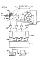
- a rotatable member is represented by the shaft 10 which is supported for rotation about an axis 12. It is desired to determine accurately the angular position of this shaft.
- a small disc 15 is fixed to the shaft 10.
- the disc pattern is divided in half, as shown, by having two separate areas 15A and 15B of different optical properties, such that each will attenuate energy directed thereon (orthrough) in a distinctly different manner. This may be achieved in any suitable manner, as by constructing the disc of different halves, or appropriately coating its surface, to obtain the desired result.
- the disc is provided with suitable coatings which make one half of its surface reflective and the other half absorptive. It should be noted that each of the different halves of the disc covers two quadrants of the disc surface.
- the disc is described as "fixed" to the member or shaft under observation, but it should be understood that such fixation may be of temporary nature, for example when using the invention in testing or asssembling operations. However, the fixing of the disc to the shaft, even if temporary, is tight enough that the two rotate together.
- the surface of the disc is uniformly flooded with radiant energy of desired wavelength. In some uses, this may simply be ambient light (daylight or artificial) if such wavelengths are satisfactory. Where it is desired to minimize optical interference from ambient light, it is useful to utilize a source of radiant energy in the invisible part of the spectrum, e.g. infrared light, and this is illustrated in Fig.
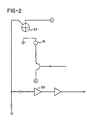
- FIG. 1 as an infrared LED (light emitting diode) 16 which is connected to a suitable power source via an electronic switch 18. Details of a suitable circuit are shown in Fig. 2.
- the trigger input to the switch 18 provides a way to control or "strobe" the light output of the LED for timing purposes and to discriminate the LED output from slowly varying natural radiation sources.
- the radiant energy from the LED light source is reflected differently by the two different parts 15A and 15B of the disc, and the encoded energy is directed through a simple lens system 20 which focuses an image (inverted and reversed) onto the quad detector 22.
- This is a commercially available device which is available with different response characteristics, in this case being responsive to a range of intensity of infrared light as emitted from the LED.
- Detector 22 is comprised of four photodetector elements Q1, Q2, Q3 and Q4, each of which has a distinct output signal line 24A, 24B, 24C, and 24D which lead to individual electronic amplifiers 25A, 25B, 25C, and 25D.
- the power supply and amplifier circuit for one element Q4 is shown in Fig. 2.
- the amplified output signals thus are an analog representation of the quantity of radiant energy directed to the respective quadrant elements of the sensor 22.
- each amplifier is connected to the inputs of conventional analog-to-digital (A to D) converter circuits 28A, 28B, 28C, and 28D which generate four digital outputs on their outputs 29A, 29B, 29C, and 29D.
- a to D analog-to-digital
- This group or set of digital words defines a specific angular position of disc 15, and thus shaft 10, with respect to the fixed position of sensor 22.
- angle 0° is a vector from the center of the detector extending between the segments Q1 and Q2 and the corresponding shaft angle 0° locates the disc with the line between the sections 15A and 15B extending horizontally and the section 15B at the top, whereby there is maximum illumination of the segments Q1 and Q2 and minimum illumination of segments Q3 and Q4.
- a set of digital words is-thus transmitted for each reading to apparatus for converting this information into an angular representation or expression.
- a preferred apparatus for this purpose is a microcomputer 30.
- a Commodore 64 (TM) unit with a 6502 microprocessor is used.
- the angular representation which it calculates can be used to drive a conventional display device 32, and/or the representation can be recorded by a suitable printer 34.
- the output signals from segments Q1 and Q2 will be the maximum i.e. corresponding to full radiant energy thereon, and the output signals from segments Q3 and Q4 will be minimum, i.e. the least amount of reflection possible; note that this assumes an inversion and a side-to-side reversal of the radiant light image by the lens. It follows that, proceeding clockwise as the sensor is shown in Fig. 1, angle 90° will have Q1 and Q4 at full maximum signal, at 180° Q4 and Q3 will be at full signal, and at 270° Q3 and Q2 will be at full signal.
- the signal outputs S1, S2, S3 and S4 from the four quadrants of the detector can be translated into an angle by using the following sequence of mathematical operations (uniform illumination of the pattern and identical sensitivity of each detector quadrant is assumed for simplicity).
- This analysis technique is insensitive to small decenters of the pattern image on the quad detector since it finds the bisector of the energy distribution.
- Steps 4000 through 4500 read the AD/outputs, execute the comparisons for stability and perform the centering calculations. If these are not required in a particular installation, they may be deleted. Steps 4510 through 5000 perform the calculation of the angular representations.
Landscapes
- Physics & Mathematics (AREA)
- General Physics & Mathematics (AREA)
- Optical Transform (AREA)
- Length Measuring Devices By Optical Means (AREA)
- Transmission And Conversion Of Sensor Element Output (AREA)
- Vehicle Body Suspensions (AREA)
Applications Claiming Priority (2)
| Application Number | Priority Date | Filing Date | Title |
|---|---|---|---|
| US624156 | 1984-06-24 | ||
| US06/624,156 US4587513A (en) | 1984-06-25 | 1984-06-25 | Noncontact shaft angle detector |
Publications (3)
| Publication Number | Publication Date |
|---|---|
| EP0169657A2 EP0169657A2 (en) | 1986-01-29 |
| EP0169657A3 EP0169657A3 (en) | 1986-11-12 |
| EP0169657B1 true EP0169657B1 (en) | 1990-09-19 |
Family
ID=24500881
Family Applications (1)
| Application Number | Title | Priority Date | Filing Date |
|---|---|---|---|
| EP85304315A Expired - Lifetime EP0169657B1 (en) | 1984-06-25 | 1985-06-17 | Non-contact shaft angle detector |
Country Status (12)
| Country | Link |
|---|---|
| US (1) | US4587513A (da) |
| EP (1) | EP0169657B1 (da) |
| JP (1) | JPS6114518A (da) |
| AU (1) | AU569686B2 (da) |
| DE (1) | DE3579767D1 (da) |
| DK (1) | DK162908C (da) |
| GB (1) | GB2162635B (da) |
| IE (1) | IE56671B1 (da) |
| IL (1) | IL75604A0 (da) |
| NO (1) | NO169865C (da) |
| NZ (1) | NZ212463A (da) |
| ZA (1) | ZA854600B (da) |
Families Citing this family (29)
| Publication number | Priority date | Publication date | Assignee | Title |
|---|---|---|---|---|
| JPS63150624A (ja) * | 1986-12-16 | 1988-06-23 | Yoshida Kogyo Kk <Ykk> | エンコ−ダ−のパルス判断方法 |
| JPS63311119A (ja) * | 1987-06-15 | 1988-12-19 | Fanuc Ltd | 絶対位置エンコ−ダ |
| GB8719154D0 (en) * | 1987-08-13 | 1987-09-23 | Coal Industry Patents Ltd | Optically measuring relative angular movement |
| US4808817A (en) * | 1987-11-23 | 1989-02-28 | Sundstrand Corporation | Rotational acceleration detector with microdot coding |
| FR2644239B1 (fr) * | 1989-03-13 | 1994-04-01 | Spectec Sa | Chaine de mesure d'angle ou de position optique et a transmission par fibres optiques intrinsequement lineaire et reference utilisant une ou plusieurs sources lumineuses |
| JPH0752345B2 (ja) * | 1989-03-30 | 1995-06-05 | ヤマハ株式会社 | イニシャルタッチ制御装置 |
| US5241124A (en) * | 1990-04-18 | 1993-08-31 | Yamaha Corporation | Electronic musical instrument capable of controlling touch response based on a reference value |
| US5235180A (en) * | 1992-03-05 | 1993-08-10 | General Scanning, Inc. | Rotary motor having an angular position transducer and galvanometer scanning system employing such motor |
| JP2570945B2 (ja) * | 1992-06-16 | 1997-01-16 | カシオ計算機株式会社 | 楽音発生装置 |
| JPH087587B2 (ja) * | 1992-06-16 | 1996-01-29 | カシオ計算機株式会社 | 楽音発生装置 |
| US5442281A (en) * | 1993-06-01 | 1995-08-15 | Enscan, Inc. | Method and apparatus for deriving power consumption information from the angular motion of a rotating disk in a watt hour meter |
| US6483104B1 (en) * | 1996-09-23 | 2002-11-19 | Valeo Schalter Und Sensoren Gmbh | Rotational angle sensor using a CCD line with enhanced measuring precision |
| GB9926574D0 (en) * | 1999-11-11 | 2000-01-12 | Renishaw Plc | Absolute position measurement |
| US6396052B1 (en) | 2000-04-07 | 2002-05-28 | Lexmark International, Inc. | High precision analog encoder system |
| US6507016B1 (en) | 2000-04-18 | 2003-01-14 | Trw Inc. | Apparatus and method for sensing a vehicle rollover condition |
| US6495820B1 (en) | 2000-10-02 | 2002-12-17 | Trw Inc. | Sensor apparatus and method for sensing angular rotation of an object using light reflected off a rotor and bifurcation compensation |
| AU2002230747A1 (en) * | 2000-12-21 | 2002-07-08 | The Gleason Works | Stroking speed adjustment for shaping machine |
| DE10257494B4 (de) * | 2002-12-10 | 2011-01-27 | Matthias Zahn | Bestimmen von Attributen der Drehbewegung eines Objektes |
| US7102123B2 (en) * | 2003-10-28 | 2006-09-05 | Avago Technologies Ecbu Ip (Singapore) Pte. Ltd. | Reflective imaging encoder |
| KR101240792B1 (ko) * | 2005-10-13 | 2013-03-07 | 하마마츠 포토닉스 가부시키가이샤 | 엔코더 및 엔코더용 수광장치 |
| IL175831A0 (en) * | 2006-05-22 | 2007-08-19 | Igor Fridland | Angular position sensor |
| CN101636638B (zh) * | 2006-06-19 | 2013-06-05 | 杰斯集团公司 | 使用反射照明光的光学位置传感系统和方法 |
| JP2008096205A (ja) * | 2006-10-10 | 2008-04-24 | Hamamatsu Photonics Kk | エンコーダ及びエンコーダ用受光装置 |
| JP4890190B2 (ja) * | 2006-10-10 | 2012-03-07 | 浜松ホトニクス株式会社 | エンコーダ |
| FR2926633B1 (fr) * | 2008-01-18 | 2010-12-24 | Crouzet Automatismes | Capteur optique |
| WO2009103342A1 (en) | 2008-02-22 | 2009-08-27 | Trimble Jena Gmbh | Angle measurement device and method |
| US8212202B2 (en) * | 2009-01-08 | 2012-07-03 | Avago Technologies Ecbu Ip (Singapore) Pte. Ltd. | Reflective optical encoder package and method |
| DE102018133120A1 (de) * | 2018-12-20 | 2020-06-25 | Universität Rostock | Vorrichtung und Verfahren zur berührungslosen Rotationsmessung |
| CN116989827B (zh) * | 2023-09-28 | 2023-12-19 | 深圳舜昌自动化控制技术有限公司 | 接近式传感器防电磁干扰方法、装置、设备及存储介质 |
Citations (1)
| Publication number | Priority date | Publication date | Assignee | Title |
|---|---|---|---|---|
| US4421980A (en) * | 1980-09-17 | 1983-12-20 | Carl-Zeiss-Stiftung, Heidenheim/Brenz | Position encoder with closed-ring diode array |
Family Cites Families (8)
| Publication number | Priority date | Publication date | Assignee | Title |
|---|---|---|---|---|
| US3603688A (en) * | 1967-11-08 | 1971-09-07 | Perkin Elmer Corp | Alignment apparatus |
| US3610936A (en) * | 1969-03-20 | 1971-10-05 | North American Rockwell | Apparatus for determining the position of a discrete target occurring within a field of view |
| US3918814A (en) * | 1974-05-13 | 1975-11-11 | Weiser Robodyne Corp | Optical position sensor |
| DE2646674A1 (de) * | 1974-09-30 | 1977-04-21 | Keystone Int | Lageempfindliches abtast-bedienungssystem |
| US4320293A (en) * | 1978-08-30 | 1982-03-16 | Harold Guretzky | Angle-position transducer |
| US4327362A (en) * | 1978-10-23 | 1982-04-27 | Rockwell International Corporation | Meter rotor rotation optical sensor |
| US4321531A (en) * | 1979-09-17 | 1982-03-23 | Sangamo-Weston Inc. | Direction sensitive pulse initiator for a wattmeter |
| DE3201163A1 (de) * | 1982-01-15 | 1983-07-28 | Siemens AG, 1000 Berlin und 8000 München | Vorrichtung zur drehwinkelermittlung |
-
1984
- 1984-06-25 US US06/624,156 patent/US4587513A/en not_active Expired - Fee Related
-
1985
- 1985-06-17 DE DE8585304315T patent/DE3579767D1/de not_active Expired - Lifetime
- 1985-06-17 AU AU43806/85A patent/AU569686B2/en not_active Ceased
- 1985-06-17 EP EP85304315A patent/EP0169657B1/en not_active Expired - Lifetime
- 1985-06-18 GB GB08515358A patent/GB2162635B/en not_active Expired
- 1985-06-18 ZA ZA854600A patent/ZA854600B/xx unknown
- 1985-06-19 NZ NZ212463A patent/NZ212463A/en unknown
- 1985-06-21 IE IE1551/85A patent/IE56671B1/en not_active IP Right Cessation
- 1985-06-24 NO NO852532A patent/NO169865C/no unknown
- 1985-06-24 JP JP60136209A patent/JPS6114518A/ja active Pending
- 1985-06-24 IL IL75604A patent/IL75604A0/xx not_active IP Right Cessation
- 1985-06-24 DK DK284885A patent/DK162908C/da not_active IP Right Cessation
Patent Citations (1)
| Publication number | Priority date | Publication date | Assignee | Title |
|---|---|---|---|---|
| US4421980A (en) * | 1980-09-17 | 1983-12-20 | Carl-Zeiss-Stiftung, Heidenheim/Brenz | Position encoder with closed-ring diode array |
Also Published As
| Publication number | Publication date |
|---|---|
| JPS6114518A (ja) | 1986-01-22 |
| AU4380685A (en) | 1986-02-20 |
| GB2162635B (en) | 1988-05-11 |
| GB8515358D0 (en) | 1985-07-17 |
| GB2162635A (en) | 1986-02-05 |
| IE851551L (en) | 1985-12-25 |
| US4587513A (en) | 1986-05-06 |
| DK284885A (da) | 1985-12-26 |
| DK162908B (da) | 1991-12-23 |
| NO169865B (no) | 1992-05-04 |
| NO852532L (no) | 1985-12-27 |
| EP0169657A3 (en) | 1986-11-12 |
| GB2162635A8 (en) | 2001-07-25 |
| IL75604A0 (en) | 1985-10-31 |
| IE56671B1 (en) | 1991-10-23 |
| EP0169657A2 (en) | 1986-01-29 |
| NZ212463A (en) | 1988-02-12 |
| ZA854600B (en) | 1986-02-26 |
| DK162908C (da) | 1992-07-06 |
| NO169865C (no) | 1992-08-12 |
| DE3579767D1 (de) | 1990-10-25 |
| DK284885D0 (da) | 1985-06-24 |
| AU569686B2 (en) | 1988-02-11 |
Similar Documents
| Publication | Publication Date | Title |
|---|---|---|
| EP0169657B1 (en) | Non-contact shaft angle detector | |
| US4421980A (en) | Position encoder with closed-ring diode array | |
| KR20010074741A (ko) | 각 인코더 | |
| US4443108A (en) | Optical analyzing instrument with equal wavelength increment indexing | |
| CA1213369A (en) | Method and apparatus for determining measured quantities | |
| US4746792A (en) | Optical transducer element and displacement meter comprising such an element | |
| US4218615A (en) | Incremental digital shaft encoder | |
| US4677293A (en) | Photoelectric measuring system | |
| US4606642A (en) | Measuring arrangement for the clear scanning of at least one reference mark allocated to a graduation | |
| JPH05500707A (ja) | 高分解能絶対エンコーダ | |
| US4433585A (en) | Device for measurement of the torsional angular deviation of a loaded rotating or static shaft | |
| US4803484A (en) | Optically readable and human readable dial | |
| US3544800A (en) | Optical apparatus for encoding angular movement of a rotating shaft | |
| US5640015A (en) | Pyrometer electromagnetic radiation measuring device | |
| US3502414A (en) | Optical electric system | |
| US5349183A (en) | Diffraction grating rotary speed sensor having a circumferentially variable pitch diffraction grating | |
| CA1056593A (en) | Apparatus for direct measurement of linear and angular displacements with digital readout | |
| US4463259A (en) | Method and apparatus for measuring the displacement of a radiation-restrictive mark, as in a surveying instrument | |
| EP0691525B1 (en) | Sensing system with a multi-channel fiber optic bundle sensitive probe | |
| SU832479A1 (ru) | Измеритель скорости и угла поворота вала | |
| SU1756756A1 (ru) | Устройство дл определени параметров вращени объектов | |
| SU1374061A1 (ru) | Дозиметр ультрафиолетового излучени | |
| KR980010375A (ko) | 디지탈 태양센서 | |
| RU1789046C (ru) | Устройство дл измерени рассто ни | |
| JPH0136044B2 (da) |
Legal Events
| Date | Code | Title | Description |
|---|---|---|---|
| PUAI | Public reference made under article 153(3) epc to a published international application that has entered the european phase |
Free format text: ORIGINAL CODE: 0009012 |
|
| AK | Designated contracting states |
Designated state(s): BE CH DE FR IT LI NL SE |
|
| PUAL | Search report despatched |
Free format text: ORIGINAL CODE: 0009013 |
|
| AK | Designated contracting states |
Kind code of ref document: A3 Designated state(s): BE CH DE FR IT LI NL SE |
|
| 17P | Request for examination filed |
Effective date: 19861030 |
|
| RAP1 | Party data changed (applicant data changed or rights of an application transferred) |
Owner name: ENERGY INNOVATIONS INC. |
|
| 17Q | First examination report despatched |
Effective date: 19880321 |
|
| GRAA | (expected) grant |
Free format text: ORIGINAL CODE: 0009210 |
|
| AK | Designated contracting states |
Kind code of ref document: B1 Designated state(s): BE CH DE FR IT LI NL SE |
|
| REF | Corresponds to: |
Ref document number: 3579767 Country of ref document: DE Date of ref document: 19901025 |
|
| ITF | It: translation for a ep patent filed | ||
| ET | Fr: translation filed | ||
| PGFP | Annual fee paid to national office [announced via postgrant information from national office to epo] |
Ref country code: FR Payment date: 19910329 Year of fee payment: 7 |
|
| PGFP | Annual fee paid to national office [announced via postgrant information from national office to epo] |
Ref country code: SE Payment date: 19910503 Year of fee payment: 7 |
|
| PGFP | Annual fee paid to national office [announced via postgrant information from national office to epo] |
Ref country code: BE Payment date: 19910517 Year of fee payment: 7 |
|
| PGFP | Annual fee paid to national office [announced via postgrant information from national office to epo] |
Ref country code: DE Payment date: 19910612 Year of fee payment: 7 |
|
| ITTA | It: last paid annual fee | ||
| PGFP | Annual fee paid to national office [announced via postgrant information from national office to epo] |
Ref country code: NL Payment date: 19910630 Year of fee payment: 7 |
|
| PGFP | Annual fee paid to national office [announced via postgrant information from national office to epo] |
Ref country code: CH Payment date: 19910715 Year of fee payment: 7 |
|
| PLBE | No opposition filed within time limit |
Free format text: ORIGINAL CODE: 0009261 |
|
| STAA | Information on the status of an ep patent application or granted ep patent |
Free format text: STATUS: NO OPPOSITION FILED WITHIN TIME LIMIT |
|
| 26N | No opposition filed | ||
| PG25 | Lapsed in a contracting state [announced via postgrant information from national office to epo] |
Ref country code: SE Effective date: 19920618 |
|
| PG25 | Lapsed in a contracting state [announced via postgrant information from national office to epo] |
Ref country code: LI Effective date: 19920630 Ref country code: CH Effective date: 19920630 Ref country code: BE Effective date: 19920630 |
|
| BERE | Be: lapsed |
Owner name: ENERGY INNOVATIONS INC. Effective date: 19920630 |
|
| PG25 | Lapsed in a contracting state [announced via postgrant information from national office to epo] |
Ref country code: NL Effective date: 19930101 |
|
| NLV4 | Nl: lapsed or anulled due to non-payment of the annual fee | ||
| PG25 | Lapsed in a contracting state [announced via postgrant information from national office to epo] |
Ref country code: FR Effective date: 19930226 |
|
| REG | Reference to a national code |
Ref country code: CH Ref legal event code: PL |
|
| PG25 | Lapsed in a contracting state [announced via postgrant information from national office to epo] |
Ref country code: DE Effective date: 19930302 |
|
| REG | Reference to a national code |
Ref country code: FR Ref legal event code: ST |
|
| EUG | Se: european patent has lapsed |
Ref document number: 85304315.6 Effective date: 19930109 |