EP0169002A2 - Spritzbeschichtungsanlagen - Google Patents
Spritzbeschichtungsanlagen Download PDFInfo
- Publication number
- EP0169002A2 EP0169002A2 EP85304679A EP85304679A EP0169002A2 EP 0169002 A2 EP0169002 A2 EP 0169002A2 EP 85304679 A EP85304679 A EP 85304679A EP 85304679 A EP85304679 A EP 85304679A EP 0169002 A2 EP0169002 A2 EP 0169002A2
- Authority
- EP
- European Patent Office
- Prior art keywords
- coating
- article
- booth
- conveyor
- spray
- Prior art date
- Legal status (The legal status is an assumption and is not a legal conclusion. Google has not performed a legal analysis and makes no representation as to the accuracy of the status listed.)
- Granted
Links
Images

Classifications
-
- B—PERFORMING OPERATIONS; TRANSPORTING
- B05—SPRAYING OR ATOMISING IN GENERAL; APPLYING FLUENT MATERIALS TO SURFACES, IN GENERAL
- B05B—SPRAYING APPARATUS; ATOMISING APPARATUS; NOZZLES
- B05B13/00—Machines or plants for applying liquids or other fluent materials to surfaces of objects or other work by spraying, not covered by groups B05B1/00 - B05B11/00
- B05B13/02—Means for supporting work; Arrangement or mounting of spray heads; Adaptation or arrangement of means for feeding work
- B05B13/0221—Means for supporting work; Arrangement or mounting of spray heads; Adaptation or arrangement of means for feeding work characterised by the means for moving or conveying the objects or other work, e.g. conveyor belts
- B05B13/0235—Means for supporting work; Arrangement or mounting of spray heads; Adaptation or arrangement of means for feeding work characterised by the means for moving or conveying the objects or other work, e.g. conveyor belts the movement of the objects being a combination of rotation and linear displacement
-
- B—PERFORMING OPERATIONS; TRANSPORTING
- B05—SPRAYING OR ATOMISING IN GENERAL; APPLYING FLUENT MATERIALS TO SURFACES, IN GENERAL
- B05B—SPRAYING APPARATUS; ATOMISING APPARATUS; NOZZLES
- B05B16/00—Spray booths
- B05B16/60—Ventilation arrangements specially adapted therefor
-
- B—PERFORMING OPERATIONS; TRANSPORTING
- B05—SPRAYING OR ATOMISING IN GENERAL; APPLYING FLUENT MATERIALS TO SURFACES, IN GENERAL
- B05B—SPRAYING APPARATUS; ATOMISING APPARATUS; NOZZLES
- B05B16/00—Spray booths
- B05B16/90—Spray booths comprising conveying means for moving objects or other work to be sprayed in and out of the booth, e.g. through the booth
-
- Y—GENERAL TAGGING OF NEW TECHNOLOGICAL DEVELOPMENTS; GENERAL TAGGING OF CROSS-SECTIONAL TECHNOLOGIES SPANNING OVER SEVERAL SECTIONS OF THE IPC; TECHNICAL SUBJECTS COVERED BY FORMER USPC CROSS-REFERENCE ART COLLECTIONS [XRACs] AND DIGESTS
- Y10—TECHNICAL SUBJECTS COVERED BY FORMER USPC
- Y10S—TECHNICAL SUBJECTS COVERED BY FORMER USPC CROSS-REFERENCE ART COLLECTIONS [XRACs] AND DIGESTS
- Y10S118/00—Coating apparatus
- Y10S118/07—Hoods
Definitions
- This invention relates to apparatus and a method for spray coating articles, such as preformed plastic containers, with a coating material.
- the invention is for example applicable to coating polyethylene terephthalate (hereafter referred to as PET) bottles with a copolymer of vinylidene chloride (hereafter referred to as PVDC) to provide the bottles with a gas barrier coating.
- PET polyethylene terephthalate
- PVDC copolymer of vinylidene chloride
- apparatus comprising a coating booth and characterised by an overspray particle collector chamber enclosing an article exit from the booth and a conveyor for moving the article for coating following a path into the booth through an article entry past the nozzle(s), through the exit and out of the collector through a collector exit.
- the coated article ducting may be connected to the chamber displaced from the article, chamber exit, the ducting being provided with a fan so that air is sucked around the article and overspray is drawn off from the chamber into the ducting and away from the article chamber exit.
- a method of spray coating an article is characterised in that after spraying,the article is conveyed through an article exit from the booth into an enclosed particle collector space, having an entry and an exit, whilst the article is within the space passing a gaseous fluid past and over the article and extracting the fluid and overspray from the space through ducting whilst continuing to convey the article out of the space.
- a solution to the problem of providing efficient spray coating apparatus using a coating booth is solved in another aspect of the invention in which the spray nozzle(s) is (are) connected to a coating supply line by means of two available lines of which are controlled by first valve means so that one of the available lines at any one time and wherein the available lines are connectable to a flushing liquid supply by a further valve means.
- a further improvement of apparatus for spray coating according to another aspect of the invention in which a conveyor conveys an article past a spray nozzle means in a spray booth is characterised in that the conveyor is provided with means mounted to the conveyor for enabling the article to be rotated on the conveyor, the means comprising an article gripping means mounted to a spindle pivotally mounted to a link pin of the conveyor and a circular bearing surface engageable by one or more belts to spin the article on the conveyor.
- PET plastic containers for beverages are coated with a PVDC gas barrier coating.
- This process is carried out by spray impacting a stream of an aqueous dispersion of film-forming polymer particles onto the substrate surface to form a gel layer having the polymer in the continuous phase of the layer.
- the process provides initially a wet uniform coating of the substrate which coating is then dried completely coalescing the material into a polymer film.
- the apparatus includes a spray coater for receiving a continuously moving line of articles e.g., containers or bottles to be coated, an oven for receiving the containers after coating for drying of the coating and a conveyor for moving the bottles into and through the coater and then into and through the drying oven.
- the speed of the line is controlled for controlling the time the bottles are in the spray coating chamber and in the drying oven.
- the spray coating chamber or booth in a presently preferred form of the invention is a vertical coater having two banks of three sets of spray nozzles vertically disposed on one side wall of the coater.
- the continuously moving lines of containers or bottles to be coated is conveyed downwardly in the coater and in front of the spray nozzles.. Conventional airless spray nozzles may be used.
- One bank of spray nozzles is operated at a time.
- the bottles to be coated pass in close proximity to the airless spray nozzles through which is passed the wet coating material such that the outside surface of the container is impacted with a stream.of the coating material to provide the outside surface of the container with a wet coating layer.
- the bottle conveyor of the preferred embodiment then carries the coated bottles vertically upward and out of the spray coating booth, to an oven, and vertically downward into the oven.
- the coating is dried by radiant heat to remove the water.
- heating is continued to film-form or completely coalesce the coating on the bottles. Drying time is short enough and the temperature low enough, however, to prevent the distortion of the bottles.
- the bottles are then conveyed out of the oven and removed from the conveyor while bottles to be coated are moved into the booth.
- the coating apparatus is both efficient and economical by providing a moving line of articles e.g. bottles through a continuous coater at coating rates, for example, of 300 bottles per minute.
- the spray coating operation is applied with a 95+% transfer efficiency.
- the spray coating booth includes a collection system for collecting the liquid overspray and returning it to be repumped to the spray nozzles. Overspray escaping from the spray chamber is contained and conducted through duct work to first dry it and then through a conventional bag filter to capture the dry film-forming particles in the overspray atmosphere.
- the system further includes valves and piping for conducting the liquid material to be coated from a bulk source to the spray nozzles.
- valves and piping for conducting the liquid material to be coated from a bulk source to the spray nozzles.
- two feed lines are provided containing filters for filtering the coating material upstream of the spray nozzles and such that one filter bank can be shut down for backwashing while the other filter bank is operable.
- the present invention provides apparatus for coating plastic substrates, e.g., PET bottles with a PVDC barrier coating, to provide coatings having superior physical properties at production rates suitable for commercial applications.
- F ig. 1 skows diagrammatically the apparatus of the present invention for the coating of bottles wherein bottles 10 carried on a conveyor 12 are conveyed into a coater or booth 14 for impact spraying of a liquid dispersion coating thereon, and then conveyed to an oven 16 where the coating layer formed on the containers is dried to remove the water from the coating and to form a thin film, without distortion of the bottles.
- the bottles 10 to be coated e.g., PET bottles to be coated with PVDC, are mounted on the conveyor 12 in line to form a spaced series of bottles to be conveyed continuously into, through and out of the coater 14 and then the oven 16.
- Each bottle extends horizontally in a chuck and spindle assembly 18 (Fig. 5) which is mounted to an extension 19 of a chain link pin 20 fixing the chain link of the conveyor 12.
- the extension 19 has a flanged ball bearing assembly 21 at one end which permits the chuck and spindle assembly 18 to rotate the spindle, in turn, rotating the bottles 10 on the conveyor 12.
- the clwck and spindle assembly 18 includes a cup 22 which grips the bottle neck to hold it to the assembly and permits removal of the bottles 10 from the assembly 18.
- the chuck and spindle assemblies 18 are regularly spaced along the chain conveyor 12 and are designed to be spun by a belt engaging the outer surface of the assembly, as will be described in detail. Although only three bottles are shown in Fig. 1 for purposes of illustration, it will be understood that chuck and spindle assemblies are provided along the entire length of the conveyor 12 for the continuous coating of bottles.
- the position of the bottles 10, as shown in Fig. 1, shows where the bottles 10 may be loaded andunloaded from the conveyor. After being loaded on the conveyor, the bottles 10 are carried by the chain conveyor 12 in the direction of the arrows in Fig. 1.
- the bottles 10 pass first around an idler sprocket 24 and then into the spray coater 14.
- Bottles 10 are conveyed through the inlet 28 into the interior of the cabinet 26 in a vertically downward path such that the bottles pass by a paired bank of impact spray nozzles 29, each bank having three spray nozzle assemblies 29a, 29b and 29c (Fig. 2) which extend through a side wall of the cabinet 14.
- a paired bank of impact spray nozzles 29a, 29b and 29c Fig. 2
- Two banks of spray nozzles are provided but only one bank is used at any one time. This permits the coating operation to operate continuously when one bank is shut down for maintenance merely by switching spray coating material to the other bank.
- Each of the nozzle assemblies 29a, 29b and 29c includes two airless spray nozzles. Suitable nozzles are airless spray nozzles, Part No. 713201, manufactured by Nordson Corporation of Amherst, Ohio.
- the nozzle assemblies 29a, 29b and 29c in each bank are laterally spaced one from another in a diagonal line so that each sprays a portion of each bottle 10 as it passes by.
- the bottle-to-nozzle distance preferably is relatively small, 3.g., on the order 64 mm (21 ⁇ 2 inches) when spraying a coating material such as a W. R. Grace 820 PVDC emulsion, at a pressure of about 45.7kg/cm 2 (650 psig) for approximately 200 msec.
- the bottles are rotated at least two revolutions as they pass by the bank of spray nozzles 29a, 29b and 29c.
- the bottles With a conveyor line speed of around 100 feet per minute, the bottles are rotated during the coating operation at speeds in the range of 200 to 800 rpm.
- the rate of rotation can be varies depending on the line speed, spray volume from the nozzles, or any other relevant parameter.
- Rotation of the bottles within the coater 14 is accomplished by means of a belt 32 mounted on a pair of timing belt sprockets 34 and 36.
- the timing belt sprocket 36 is driven by a suitable motor (not shown), with the sprocket 34 being an idler sprocket.
- a tensioner sprocket 38 is provided to maintain adequate tension in the belt 32.
- the r portion 32a of the belt 32 contacts the outer surface of the chuck and spindle assemblies 18 causing them and, as a result, the bottles to rotate in a counterclockwise direction.
- this rotational speed is in the range of 200 to 000 rpm.
- Rotation of the bottles in a direction opposite the direction of their movement past the spray nozzles causes the bottle surface to rotate into the spray to achieve in cooperation with the nozzle spray pressure and relatively small nozzle-to- bottle spacing the required impacting of the coating material on the bottle to successfully carry out the impact spray process.
- the bottles 10 After the bottles 10 have been spray coated, they continue downwardly and around a pair of idler sprockets 40 and 42 located in the bottom portion of the conveyor loop within the coater 14. Once the bottles pass around idler sprocket 42, they then move vertically upwardly through the interior of the coater cabinet 26 and out the outlet 30. The bottles on the chain conveyor 12 next pass around an idler sprocket 44 and then are conveyed to the drying oven 16.
- a spin is again imparted to the bottles 10 to prevent the coating from sagging as the bottles move between the coater 14 and the oven 16.
- a second belt 46 is provided which is carried by two timing belt sprockets 48 and 50, and which spans the distance between the coater 14 and the oven 16.
- the sprocket 50 is driven by a suitable motor (not shown) and a tension sprocket 52 is provided to maintain proper tension in the belt 46.
- a portion 46a of the belt 46 runs parallel to the path of the chain conveyor 12 and frictionally engages the outer surface of of the chuck and spindle assembly 18 to impart a rotation to the bottles.
- the distance between the coater 14 and the oven 16 varies depending on the nature of the coating material.
- a distance of 3 to 4 feet may be used.
- an inflammable solvunt- based coating is used, a separation of the coater from the heat source, such as the oven 16, is required to meet applicable codes.
- a radiant heat source is used composed of a plurality of qunrtz heaters 58 which extend vertically along one interior side wall of the oven 16 adjacent the downward path of the bottles 10 in the oven 16.
- a radiant heat source is illustrated, a convective heat source using electric heaters or some combination of radiant/convective heating could be employed.
- the bottles 10 on the conveyer 12 pass into the oven 16 through the inlet 56 and downwardly past the radiant heaters 58.
- the bottles 10 then travel on the conveyor 12 around an idler sprocket 60 and a drive sprocket 62 in the oven 16, where the conveyor path then turns vertically upwardly to carry the bottles out through an outlet 64.
- the bottles then pass around a sprocket 66 and back to the loading/unloading point.
- Drive sprocket 62 propels the entire chain conveyor 12.
- This sprocket is preferably driven by a variable speed drive motor, such as an electric motor.
- the oven 16 is of such a size in relation to the speed of the bottles passing therethrough to provide sufficient heating to the coating on the bottles to dry it throughout its thickness and to form a substantially uniform coating on the bottle surface.
- the temperature and humidity of the oven can be controlled as desired.
- a presently preferred environment for drying a PVDC coating on PET containers, for example, is 20-90% relative humidity and a temperature of 76.7-79.5°C (170-175°F)
- the exposure time of the bottles in the oven is short enough to keep the temperature of the containers below their distortion temperature but yet long enough to dry the coating to a substantially tack-free condition.
- a larger oven and/or the utilization of a serpentine path may be required for higher.line speeds of the conveyor 12. That is, to insure a sufficient dwell time within the oven 16 to effect a proper cure of the coating on the bottles, the oven may be modified so that the bottles 10 are.exposed to heat for a sufficient length of time to remove the water from the coating to complete the formation of the desired coating film The oven time, however, is still short enough to keep the temperature of the containers sufficiently low to avoid distoriton of the containers.
- the bottles 10 within the oven 16 are again spun to expose the bottles evently to the radiant heaters 58. This is accomplished by another belt 68 which is carried on three timing belt sprockets 70, 72 and 74 and drive sprocket 76. Any suitable variable speed drive motor (not shown)
- Belt 68 engages the outside surface of the chuck and spindle assembly 18, in the name manner as the belts previously described, along a length 68a of the belt which runs parallel to the downward path of the bottles to turn the spindles and thus the bottles.
- a length 68b of belt 68 also runs parallel to the upward path of the conveyor 12 to continue rotation of the bottles as they move upwardly and out of the oven 16.
- an electronic counter 78 may be used to register the travel of the chain conveyor 12 to indicate the position of a point on the chain conveyor around its circuit. This is accomplished by a small sprocket 00 which engages the chain conveyor 12 to register its travel. Alternatively, the counter can be directly connected to one of the idler sprockets with distance of chain travel correlated to rotation of that idler sprocket.
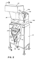
- the coater 14 is shown in more detail in Figs. 2-4. With reference to those figures, the top of the coater 14 is enclosed with duct work 02 to contain and convey overspray from the coater to a dust collector 84 for collecting oversprayed film-forming particles.
- one wall 06 of the duct 82 is formed of a mask having openings 86a and 86b, respectively, in the shape of a silhouette of the bottles being coated.
- a second mask 88 having openings 88a and 88b, which correspond to bottle inlet 28 and outlet 30 openings in Fig. 1, again in the shape of the silhouette of the bottles being coated is located at the top of the coater interiorly of the duct work 82.
- Mask 88 closes the top of the coater, except for the openings 88a and 88b, to contain the overspray within the coater as much as possible while still permitting the bottles to enter the coater through opening 88a and exit through opening 88b.
- Both of the masks 86 and 88 are readily removable to permit quick exchange when the bottles (and the bottle silhouettes) change from one type of bottle to another.
- Fig. 4 which is a back view of the coater 14
- the bottle chuck and spindle assemblies 18 extend through a U-shaped conveyor slot 90 in the back of the coater 14.
- the U-shaped slot has rubber or urethane sealing flapu 92 on opposed side edyes along the length of the conveyor slot 90.
- the flaps 92 slightly overlap to seal the slot 90 against the escape of coating material spray from the cabinet interior.
- the chuck and spindle assemblies 18 can nevertheless move easily between the flaps 92, with the slot 90 being sealed ahead of and behind each assembly.
- overspray baffle 94 is located directly opposite the spray nozzle bank 29a, 29b, 29c.
- the baffle 94 extends vertically along a substantial length of the cabinet interior. Overspray or material deflected from the bottles 10 splashes against this panel.
- a forwardly sloping baffle portion 96 at the bottom of the panels 94 acts as a gutter to catch the coating material running down the side of the vortlcal panel 94.
- the gutter which has a slight lip, 98, collects this overspray and directs it toward the front of the cabinet interior where it can then trickle down the front wall 100 of the cabinet 26 into a forwardly sloping sump 102 to a drain 104 (Fig. 3).
- a lika baffle portion 105 is located at the upper part of the baffle 94 generally parallel to the bottom portion 96.
- Baffle portion 105 is likewise forwardly sloped to permit overspray to run off the front of it onto the interior of the front wall 100 of the coater cabinet 26. It will be noted that a alight space of perhaps 1/4 inch is left between the front of each of the baffle portions 96 and 105 and the inside of the front wall 100 of the cabinet 26 to permit this fluid flow.
- the lower baffle portion 96 prevents overspray running down the vertical bottle panel 94 from dripping onto the bottles as they travel through the bottom part of the U-shaped conveyor loop in the coater 14 under and around baffle portion 96.
- the upper baffle portion 105 reduces spray from spattering upwardly out of the cabinet.
- the second mask 08 is also forwardly angled to direct any overspray accumulating on it toward the interior of the front wall 100 of the cabinet 26 where it can trickle down to the sump 102.
- Any spray which does escape beyond the baffles 94 and through the second mask 08 is in the form of a relative fine mist as it enters into the ducting 82. From the duct 82 it is captured by the dust collector 84 connected to the top of duct 82.
- An example of a suitable dust collector is a Torit Model 64 cabinet dust collector which has a plurality of fabric filters to trap dust particles of micron or greater size.
- An American Air Filter dust collector sold under the name Arrestall, Size No. 400, can also be used.
- the dust collector 84 has an internal fan which pulls ambient air through the openings 86a and 86b of the first mask 86 into the duct 82 and into the dust collector 84. Wet overspray within the duct 82 is caught in this swirling air flow as it passes up through the ducting 82 into the dust collector 84 and is thereby dried to a powder of flour-like consistency. The dried overspray powder is trapped in the dust collector 84 and can then be readily disposed of.
- a lip (not shown) can be provided along the bottom inner circumference of the ducting 82 to collect any dried particulate powder which may adhere to the interior walls of ' the duct 82 and then become dislodged and fall downwardly, e.g., by vibration of the duct.
- the dust collector is both vertically and laterally offset from the top of the coater 14 to provide clearance for.the bottles carried by the conveyor and sufficient travel distance of the overspray to dry it before reaching the collector.
- a spacing of the dust collector of about 760 mm (30 inches) vertically from the top of the chamber and offset to provide a diagonal distance from mask 88 to the collector of about 1070 mm (42 inches) has been used.
- parts of the coater below the duct 82 which come in contact with the spray coating material are made of 316 stainless steel.
- the ducting 82 is made of a plastic which is nonreactive with the spray coating material.
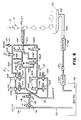
- FIG. 6 a schematic diagram of the fluid flow system is illustrated. This system provides for alternate flow paths to the pair of banks of spray nozzles 29, as well as for purging the system with water or cleaning solution.
- the illustrated flow arrangement provides for the simultaneous flow of coating material to the nozzles through one circuit of the flow path while the other circuit is being back flushed.
- a pump 108 draws coating material such as PVDC contained in a supply container or reservoir 110 through a siphon tube 112 into one of two alternate fluid flow circuits indicated by A and B.
- Pump 100 also draws water for purging the system through water line 114 into either of the two flow circuits A and B.
- a suitable pump is a Nordson Corporation 711816 pump.
- Initial selection between either water or coating material flow is made through the actuation of a three-way valve 116.
- Both the three-way valve 116 and the pump 108 are located in a connecting line 118 which includes another three-way valve 120 downstream of the pump 108.
- the three-way valve 120 is actuated to permit fluid flow either into fluid circuit A or fluid circuit B.
- three-way valves 116 and 120 are shown actuated to permit coating material to be pumped from reservoir 110 into fluid circuit B.
- the coating firnt passes through a coarse mesh filter 122B and then through a finer mesh filter 123B located in a flow line 124B.
- These filters 122B and 1238 are of a cleanable screen type having a fine mesh wrapped around a core. The filters are designed to be cleaned in situ, as by back flushing.
- a two-way valve 125B is shown in the closed position in line 1248.
- the coating flow therefore passes into a branch line 119B.
- a two-way valve 126B closed in line 127B, which connects into branch line 119B, the coating material passes through a three-way valve 128 into nozzle line 129 and from there to the nozzles 29a, 29b and 29c of the nozzle bank.
- three-way valve 120 and three-way valve 128 ard operated in conjunction in the selection of fluid flow through either circuit A or circuit B.
- circuit A To utilize circuit A instead of circuit B, as when circuit B is being back flushed or serviced three-way valves 120 and 128 are actuated to permit coating material flow through circuit A in the identical manner as just described in relation to circuit B and to close circuit D. That is, coating material pauses through three-way valve 120 into line 124h, then throuyh a coarse filter 122A and then a fine filter 123A where it encounters a closed two-way valve 125A in the line. The material then passes into a branch line 119A where it passes through three-way valve 128, since a two-way valve 126A in line 127A, which connects into line 119A, is closed. The coating material then flows out of circuit A and through nozzle line 129, to the nozzles 29a, 29b and 29c of the nozzle bank.
- circuit A can be back flushed by the introduction of water or some other cleaning fluid at line 130.
- the water flush pauses through a one-way check valve 131 and into line 124A since valve 125B in line 124B is closed. With two-way valve 125A now open to fluid flow, the flush water passes through line 124h to fine filter 123A.
- Fine filter 123A is connected to a back flush line 132A, which has a two-way dump valve 133A therein.
- Coarse filter 122A likewise has a back flush line 134A which likewise has a two-way dump valve 135A.
- Both lines 132A and 134A connect with a waste line 136 which terminates in a waste fluid receptacle (not shown).
- valve 126A is opened permitting fluid flow into line 127A and from there into line 136 to waste.
- Valves 126B, 133A and 135A are of course closed. Water id thus quickly purged from the major portion of circuit A in this manner, with only a small amount remaining to be vented through the nozzles.
- Circuit B can be treated in a like manner by opening of valve 126B in line 12711.
- Water line 114 is provided to purge the entire system, including the spray nozzles. This purge ordinarily occurs at tho end of a run, such as when the coating system is being shut down. To this end, three-way valve 116 is actuated to interconnect water flow from line 114 into line 118 while cutting off the flow of coating material. Water can then be pumped through either circuit A or circuit B, as selected at three-way valve 120, and run through the entire circuit and out the nozzles 29a, 294 and 29c.
- All piping used in the system is of 316 stainless steel or plastic.
- Suitable two-way valves for use in the coating material supply system are manufactured by Nordson Corporation, Amherst, Ohio, and are Part No. 713436.
- Suitable thrue-way valves are Whitey No. SS-44XF6 valves.
- the valves are all pneumatically operated pilot control valves indicated schematically by the notation "PV" in Fig. 6, and the two-way valves are all spring biased into a normally closed position.
- the valves could be solenoid operated, or standard ball valves manually operated.
- FIG. 6 An overspray collection and recirculation system at the bottom of the coater 14 is further shown in Fig. 6.
- a coarse screen 138 is provided in the bottom of the coater cabinet 26 above the drain 104 which permits overspray to pass into the collecting drain 104 but screens out any large debris which may get into the coater.
- the sump .102 has a slanted bottom (Figs. 3 and 4) and terminates in the coating sump drain 104.
- the drain 104 connects with a return line 140 which opens into the coating reservoir 110.
- a diaphragm sump pump 141 such as a Wilden Model No. M2 Champ, is located in return line 140 to pump the collected overspray from the coater to the coating reservoir 110.
- Pump 141 is controlled by a level detector which ensures that the overspray has a controlled risidence time in the sump to permit entrapped air to escape from the coating before it is pumped out of the sump.
- a screen or strainer 142 for catching larger particular matter which might damage the pump is located in line 140 umstream of the pump.
- a fine filter 143 such as a Filterchem FC-Al-30 type filter body made by Filterchem of Alhambra, California, having a 14 micron filter therein is located downstream from the pump.
- the overspray can be collected and returned with the above-described system to achieve greater than 95% material transfer efficiency.
Landscapes
- Spray Control Apparatus (AREA)
- Application Of Or Painting With Fluid Materials (AREA)
Applications Claiming Priority (2)
| Application Number | Priority Date | Filing Date | Title |
|---|---|---|---|
| US631403 | 1984-07-16 | ||
| US06/631,403 US4538542A (en) | 1984-07-16 | 1984-07-16 | System for spray coating substrates |
Publications (3)
| Publication Number | Publication Date |
|---|---|
| EP0169002A2 true EP0169002A2 (de) | 1986-01-22 |
| EP0169002A3 EP0169002A3 (en) | 1986-12-10 |
| EP0169002B1 EP0169002B1 (de) | 1990-06-06 |
Family
ID=24531049
Family Applications (1)
| Application Number | Title | Priority Date | Filing Date |
|---|---|---|---|
| EP85304679A Expired - Lifetime EP0169002B1 (de) | 1984-07-16 | 1985-07-01 | Spritzbeschichtungsanlagen |
Country Status (6)
| Country | Link |
|---|---|
| US (1) | US4538542A (de) |
| EP (1) | EP0169002B1 (de) |
| JP (1) | JPS6133271A (de) |
| AU (1) | AU567052B2 (de) |
| CA (1) | CA1236285A (de) |
| DE (1) | DE3578043D1 (de) |
Cited By (1)
| Publication number | Priority date | Publication date | Assignee | Title |
|---|---|---|---|---|
| GB2298152A (en) * | 1995-02-25 | 1996-08-28 | Edward Christopher Gummer | Powder coating apparatus |
Families Citing this family (50)
| Publication number | Priority date | Publication date | Assignee | Title |
|---|---|---|---|---|
| US4635585A (en) * | 1985-10-15 | 1987-01-13 | Nordson Corporation | System for spray coating substrates |
| US4662309A (en) * | 1986-04-22 | 1987-05-05 | Nordson Corporation | Portable powder spray booth |
| EP0253026A1 (de) * | 1986-07-18 | 1988-01-20 | FECO Engineered Systems, Inc. | Verfahren und Vorrichtung zum Beschichten und Nachbehandeln von Behältern |
| DE3838927A1 (de) * | 1988-11-17 | 1990-05-23 | Columbus System Patent Ag | Langgut-pulverbeschichtungsanlage |
| US5136971A (en) * | 1990-12-27 | 1992-08-11 | Metokote Corporation | Apparatus for transporting articles |
| US5482745A (en) * | 1993-11-29 | 1996-01-09 | Dana Corporation | Spray coating process and apparatus |
| US5711289A (en) * | 1995-01-17 | 1998-01-27 | Nordson Corporation | Vapor removal system for bulk adhesive handling systems |
| US5582957A (en) | 1995-03-28 | 1996-12-10 | Eastman Kodak Company | Resuspension optimization for photographic nanosuspensions |
| DE19517915A1 (de) * | 1995-05-16 | 1996-11-21 | Elringklinger Gmbh | Verfahren zur Herstellung von elastomerbeschichteten Metallagendichtungen |
| US5658383A (en) * | 1995-05-16 | 1997-08-19 | Cutshall; Taylor K. | Liquid coating apparatus |
| TWI250934B (en) * | 1997-10-17 | 2006-03-11 | Advancsd Plastics Technologies | Barrier-coated polyester articles and the fabrication method thereof |
| US6352426B1 (en) | 1998-03-19 | 2002-03-05 | Advanced Plastics Technologies, Ltd. | Mold for injection molding multilayer preforms |
| US6312641B1 (en) | 1997-10-17 | 2001-11-06 | Plastic Fabrication Technologies Llc | Method of making containers and preforms incorporating barrier materials |
| USD410015S (en) | 1998-04-06 | 1999-05-18 | Nordson Corporation | Lid assembly for a hot melt adhesive applicator |
| US6039217A (en) * | 1998-04-07 | 2000-03-21 | Nordson Corporation | Apparatus and method for thermoplastic material handling |
| DK1842898T3 (da) | 1999-07-22 | 2012-08-13 | Diversey Inc | Anvendelse af en smøremiddelsammensætning til at smøre et transportbælte |
| ATE288387T1 (de) | 1999-08-16 | 2005-02-15 | Ecolab Inc | Verfahren zum schmieren von auf förderband transportieten gebinden |
| US7384895B2 (en) * | 1999-08-16 | 2008-06-10 | Ecolab Inc. | Conveyor lubricant, passivation of a thermoplastic container to stress cracking and thermoplastic stress crack inhibitor |
| US6495494B1 (en) * | 2000-06-16 | 2002-12-17 | Ecolab Inc. | Conveyor lubricant and method for transporting articles on a conveyor system |
| US6427826B1 (en) | 1999-11-17 | 2002-08-06 | Ecolab Inc. | Container, such as a food or beverage container, lubrication method |
| DE19942534A1 (de) * | 1999-09-07 | 2001-03-08 | Henkel Ecolab Gmbh & Co Ohg | Fluorhaltige Schmiermittel |
| US7364033B2 (en) * | 1999-11-17 | 2008-04-29 | Ecolab Inc. | Container, such as a food or beverage container, lubrication method |
| FR2804405B1 (fr) * | 2000-01-28 | 2002-05-10 | Schmalbach Lubeca | Procede et appareil de stockage de preformes plastiques dans un container, procede et installation de fabrication et de stockage de preformes plastiques |
| US6806240B1 (en) | 2000-08-14 | 2004-10-19 | Ecolab Inc. | Conveyor lubricant, passivation of a thermoplastic container to stress cracking, and thermoplastics stress crack inhibitor |
| AU2001288916B2 (en) | 2000-09-05 | 2007-05-10 | Advanced Plastics Technologies Luxembourg S.A. | Multilayer containers and preforms having barrier properties utilizing recycled material |
| US6576298B2 (en) * | 2000-09-07 | 2003-06-10 | Ecolab Inc. | Lubricant qualified for contact with a composition suitable for human consumption including a food, a conveyor lubrication method and an apparatus using droplets or a spray of liquid lubricant |
| US6509302B2 (en) | 2000-12-20 | 2003-01-21 | Ecolab Inc. | Stable dispersion of liquid hydrophilic and oleophilic phases in a conveyor lubricant |
| EG23499A (en) | 2002-07-03 | 2006-01-17 | Advanced Plastics Technologies | Dip, spray, and flow coating process for forming coated articles |
| AU2003285192A1 (en) | 2002-11-08 | 2004-06-03 | Advanced Plastics Technologies Ltd | Injection mold having a wear resistant portion and a high heat transfer portion and a method for forming a preform |
| US7150902B2 (en) * | 2004-04-07 | 2006-12-19 | Pepsico, Inc. | High Tg coatings |
| ES2321421T3 (es) * | 2004-04-16 | 2009-06-05 | Advanced Plastics Technologies Luxembourg S.A. | Reforma y procedimientos de fabricacion de la preforma y una botella. |
| BRPI0511664A (pt) | 2004-06-10 | 2008-01-02 | Advanced Plastics Technologies | métodos e sistemas para o controle de temperaturas de moldes |
| US20090101068A1 (en) * | 2004-11-15 | 2009-04-23 | Vmi Epe Holland Bv | Roll Coater Assembly System |
| US7741257B2 (en) * | 2005-03-15 | 2010-06-22 | Ecolab Inc. | Dry lubricant for conveying containers |
| US7745381B2 (en) | 2005-03-15 | 2010-06-29 | Ecolab Inc. | Lubricant for conveying containers |
| US7806073B2 (en) * | 2005-03-22 | 2010-10-05 | Cytonix Llc | System and method for coating articles |
| US7717697B2 (en) | 2005-08-30 | 2010-05-18 | Sharon Hutchinson | Methods and systems for controlling mold temperatures |
| US7727941B2 (en) * | 2005-09-22 | 2010-06-01 | Ecolab Inc. | Silicone conveyor lubricant with stoichiometric amount of an acid |
| US7915206B2 (en) * | 2005-09-22 | 2011-03-29 | Ecolab | Silicone lubricant with good wetting on PET surfaces |
| US7644512B1 (en) * | 2006-01-18 | 2010-01-12 | Akrion, Inc. | Systems and methods for drying a rotating substrate |
| ITRM20060277A1 (it) * | 2006-05-24 | 2007-11-25 | Sipa Societa Industrializzazio | Impianto e processo di verniciatura di contenitori |
| US7741255B2 (en) * | 2006-06-23 | 2010-06-22 | Ecolab Inc. | Aqueous compositions useful in filling and conveying of beverage bottles wherein the compositions comprise hardness ions and have improved compatibility with pet |
| WO2008121998A1 (en) * | 2007-03-29 | 2008-10-09 | Vmi Holland B.V. | Spindle spray coating system |
| US9359579B2 (en) | 2010-09-24 | 2016-06-07 | Ecolab Usa Inc. | Conveyor lubricants including emulsions and methods employing them |
| EP4410935B1 (de) | 2013-03-11 | 2026-01-21 | Ecolab USA Inc. | Schmierung von transferplatten mit öl-in-wasser-emulsionen |
| TWI495515B (zh) * | 2013-07-31 | 2015-08-11 | Asia Neo Tech Ind Co Ltd | Substrate double - sided spraying method |
| US10239088B2 (en) | 2017-03-22 | 2019-03-26 | Ford Motor Company | Fluid application system adapted to collect and reuse reclaimed fluid |
| CN108855713B (zh) * | 2018-08-01 | 2020-04-14 | 宁波高新区意川汽车零部件有限公司 | 一种汽车用圆管内壁喷漆装置 |
| CN118002387B (zh) * | 2024-04-10 | 2024-06-28 | 山东熠阳工业技术有限公司 | 一种板材加工用喷漆装置 |
| CN119287906B (zh) * | 2024-12-13 | 2025-03-14 | 成都建工集团有限公司 | 地下室排水的防渗漏液体喷涂装置 |
Family Cites Families (14)
| Publication number | Priority date | Publication date | Assignee | Title |
|---|---|---|---|---|
| US1553133A (en) * | 1924-05-28 | 1925-09-08 | John D Bowman | Glazing machine |
| US2210187A (en) * | 1938-09-20 | 1940-08-06 | Hazel Atlas Glass Co | Bottle stabilizer |
| US2247963A (en) * | 1939-06-29 | 1941-07-01 | Harper J Ransburg | Apparatus for spray coating articles |
| US2425642A (en) * | 1944-05-20 | 1947-08-12 | Gardner Richardson Co | Sealable carton for frozen foods |
| US2505063A (en) * | 1947-09-08 | 1950-04-25 | Victor Ind Corp | Selective spraying machine for containers |
| US2528087A (en) * | 1948-01-02 | 1950-10-31 | Kwikset Locks Inc | Apparatus for spray coating |
| US3989001A (en) * | 1966-12-16 | 1976-11-02 | Continental Can Company, Inc. | Machine for spray-coating can body exteriors |
| US3513808A (en) * | 1967-10-30 | 1970-05-26 | Modern Decorating Co | Paint spray device |
| US3902453A (en) * | 1974-03-22 | 1975-09-02 | Indian Head Inc | Ultra high speed bottle coating system and process |
| US4009301A (en) * | 1974-09-05 | 1977-02-22 | Owens-Illinois, Inc. | Method for powder coating |
| US4099486A (en) * | 1977-03-28 | 1978-07-11 | Owens-Illinois, Inc. | Electrostatically coating hollow glass articles |
| SU674799A1 (ru) * | 1977-11-16 | 1979-07-25 | Ворошиловградский Филиал Проектно-Технологического Института Автоматизации И Механизации Производства | Лини дл окраски изделий в электрическом поле |
| US4600608A (en) * | 1981-10-17 | 1986-07-15 | Lucas Industries | Surface coating apparatus and method |
| EP0090606A3 (de) * | 1982-03-29 | 1984-07-11 | Nordson Corporation | Kontinuierliches Verfahren zur Rückgewinnung von Lösungsmitteln aus einer Beschichtungsanlage |
-
1984
- 1984-07-16 US US06/631,403 patent/US4538542A/en not_active Expired - Fee Related
-
1985
- 1985-06-27 CA CA000485625A patent/CA1236285A/en not_active Expired
- 1985-07-01 DE DE8585304679T patent/DE3578043D1/de not_active Expired - Lifetime
- 1985-07-01 EP EP85304679A patent/EP0169002B1/de not_active Expired - Lifetime
- 1985-07-10 AU AU44748/85A patent/AU567052B2/en not_active Ceased
- 1985-07-16 JP JP15528485A patent/JPS6133271A/ja active Pending
Cited By (2)
| Publication number | Priority date | Publication date | Assignee | Title |
|---|---|---|---|---|
| GB2298152A (en) * | 1995-02-25 | 1996-08-28 | Edward Christopher Gummer | Powder coating apparatus |
| GB2298152B (en) * | 1995-02-25 | 1999-06-16 | Edward Christopher Gummer | Improvements in or relating to powder coating apparatus |
Also Published As
| Publication number | Publication date |
|---|---|
| AU4474885A (en) | 1986-01-23 |
| CA1236285A (en) | 1988-05-10 |
| AU567052B2 (en) | 1987-11-05 |
| EP0169002B1 (de) | 1990-06-06 |
| DE3578043D1 (de) | 1990-07-12 |
| JPS6133271A (ja) | 1986-02-17 |
| EP0169002A3 (en) | 1986-12-10 |
| US4538542A (en) | 1985-09-03 |
Similar Documents
| Publication | Publication Date | Title |
|---|---|---|
| EP0169002A2 (de) | Spritzbeschichtungsanlagen | |
| US4784169A (en) | Apparatus for treating articles with solution to remove solids and then filtering the solution | |
| US20180065135A1 (en) | Spray applicating line and assembly for producing a coated part and including multiple overspray and recapture/recycle configurations | |
| JP3749095B2 (ja) | チップ型電子部品分離洗浄乾燥装置 | |
| NL7909137A (nl) | Werkwijze en inrichting voor het gezamenlijk verven van een aantal onderdelen. | |
| NZ216906A (en) | Spray paint booth for applying powders to sheet materials | |
| US5566697A (en) | Oscillator screen cleaning apparatus | |
| JPH0647229A (ja) | 湿式集塵装置 | |
| JP3105957B2 (ja) | 簡易塗装ブース | |
| KR100291745B1 (ko) | 페인트스프레이부스 | |
| EP0115321A2 (de) | Spritzkabine mit Puderrückgewinnungsanlage | |
| JPH10165864A (ja) | 水溶性塗料の塗装装置 | |
| GB2152398A (en) | Apparatus for chemically removing solid matter from articles | |
| JPS63500438A (ja) | 粒子沈着装置 | |
| JPH1099751A (ja) | 水溶性塗料の塗装装置 | |
| EP0220055B1 (de) | System zum Beschichten einer Oberfläche | |
| JPH06142573A (ja) | 塗装方法および装置 | |
| JPH07213966A (ja) | 塗装ブース | |
| JP3390600B2 (ja) | 回収型水溶性塗料の塗装装置 | |
| EP1332802A2 (de) | Lackspritzkabine | |
| JPH097938A (ja) | 塗布装置およびその制御方法 | |
| JPS6082121A (ja) | 空調空気中の塗料ミスト除去装置 | |
| JPS6031534B2 (ja) | 微粒子用集塵装置 | |
| JP2002301419A (ja) | ブレードコータおよび塗工液の回収方法 | |
| WO1991007234A1 (en) | Improved finish spray apparatus and method |
Legal Events
| Date | Code | Title | Description |
|---|---|---|---|
| PUAI | Public reference made under article 153(3) epc to a published international application that has entered the european phase |
Free format text: ORIGINAL CODE: 0009012 |
|
| AK | Designated contracting states |
Designated state(s): BE CH DE FR GB LI NL |
|
| PUAL | Search report despatched |
Free format text: ORIGINAL CODE: 0009013 |
|
| AK | Designated contracting states |
Kind code of ref document: A3 Designated state(s): BE CH DE FR GB LI NL |
|
| 17P | Request for examination filed |
Effective date: 19870602 |
|
| 17Q | First examination report despatched |
Effective date: 19880120 |
|
| GRAA | (expected) grant |
Free format text: ORIGINAL CODE: 0009210 |
|
| AK | Designated contracting states |
Kind code of ref document: B1 Designated state(s): BE CH DE FR GB LI NL |
|
| PG25 | Lapsed in a contracting state [announced via postgrant information from national office to epo] |
Ref country code: NL Effective date: 19900606 Ref country code: LI Effective date: 19900606 Ref country code: FR Effective date: 19900606 Ref country code: CH Effective date: 19900606 Ref country code: BE Effective date: 19900606 |
|
| REF | Corresponds to: |
Ref document number: 3578043 Country of ref document: DE Date of ref document: 19900712 |
|
| PG25 | Lapsed in a contracting state [announced via postgrant information from national office to epo] |
Ref country code: GB Effective date: 19900806 |
|
| REG | Reference to a national code |
Ref country code: CH Ref legal event code: PL |
|
| EN | Fr: translation not filed | ||
| NLV1 | Nl: lapsed or annulled due to failure to fulfill the requirements of art. 29p and 29m of the patents act | ||
| PLBE | No opposition filed within time limit |
Free format text: ORIGINAL CODE: 0009261 |
|
| STAA | Information on the status of an ep patent application or granted ep patent |
Free format text: STATUS: NO OPPOSITION FILED WITHIN TIME LIMIT |
|
| GBPC | Gb: european patent ceased through non-payment of renewal fee | ||
| PG25 | Lapsed in a contracting state [announced via postgrant information from national office to epo] |
Ref country code: DE Effective date: 19910403 |
|
| 26N | No opposition filed |