EP0168664A2 - Positionsanzeigende Anordnung - Google Patents
Positionsanzeigende Anordnung Download PDFInfo
- Publication number
- EP0168664A2 EP0168664A2 EP85107578A EP85107578A EP0168664A2 EP 0168664 A2 EP0168664 A2 EP 0168664A2 EP 85107578 A EP85107578 A EP 85107578A EP 85107578 A EP85107578 A EP 85107578A EP 0168664 A2 EP0168664 A2 EP 0168664A2
- Authority
- EP
- European Patent Office
- Prior art keywords
- position indicating
- indicating system
- target
- primary
- laser beam
- Prior art date
- Legal status (The legal status is an assumption and is not a legal conclusion. Google has not performed a legal analysis and makes no representation as to the accuracy of the status listed.)
- Withdrawn
Links
Images
Classifications
-
- G—PHYSICS
- G01—MEASURING; TESTING
- G01B—MEASURING LENGTH, THICKNESS OR SIMILAR LINEAR DIMENSIONS; MEASURING ANGLES; MEASURING AREAS; MEASURING IRREGULARITIES OF SURFACES OR CONTOURS
- G01B11/00—Measuring arrangements characterised by the use of optical techniques
- G01B11/26—Measuring arrangements characterised by the use of optical techniques for measuring angles or tapers; for testing the alignment of axes
- G01B11/27—Measuring arrangements characterised by the use of optical techniques for measuring angles or tapers; for testing the alignment of axes for testing the alignment of axes
Definitions
- This invention relates to a position indicating system employing an alignment laser beam or beams, and is particularly, but not necessarily exclusively, concerned with the alignment of tunnels during boring or alignment during pipe jacking.
- Alignment lasers are already well known, and have the advantage of providing a continuous reference beam projected along, e.g., a tunnel, during boring, for correct alignment of the axis of the tunnel in respect of both the so-called x- and y- axes directions. So long as the beam is correctly set, such systems are highly efficient but a major difficulty particularly when tunnel boring stems from the fact that the laser beam generating equipment must be installed in the tunnelling shaft at the beginning of the tunnel. Because of the unavoidable activity and vibration in that area, it is almost inevitable that the beam direction will be disturbed in either or both of the x- and y- axes directions.
- the object of the present invention is to provide relatively simple means for the continuous monitoring of the x-axis alignment of a laser beam.
- a position indicating system using an alignment laser beam comprises a beam splitter located in the beam path to provide a primary beam for the purpose of establishing a datum line and a secondary beam for projection onto a target.
- the beam splitter is an optical prism.
- the optical prism can be mounted in the output beam from a laser tube to provide a primary beam which can be set to indicate the required direction of the axis of the tunnel, and a secondary beam projecting from the prism at a pre-determined angle onto the inside periphery of the tunnel shaft.
- a target can be placed on the inside wall of the tunnel shaft with the secondary beam at its centre.
- the secondary beam is projected at a relatively shallow angle in any convenient direciton, it is preferably in a vertical direction above the primary beam.
- the target may be a visual target, when movement of the secondary beam from the centre of the target gives an immediate fully visible indication that misalignment has taken place and when adjustment of the equipment to sight the secondary beam at the centre of its target automatically realigns the primary beam on the required datum line,
- the target may be a light sensing detector means such as a number of photoelectric diodes capable of sensing movement of the secondary beam, the output from the diodes being capable of amplification and used to signal a required drive of an alignment motor associated with the laser producing equipment to bring the secondary beam, and hence the primary beam, back to a predetermined direction.
- a light sensing detector means such as a number of photoelectric diodes capable of sensing movement of the secondary beam, the output from the diodes being capable of amplification and used to signal a required drive of an alignment motor associated with the laser producing equipment to bring the secondary beam, and hence the primary beam, back to a predetermined direction.
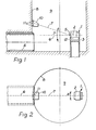
- the position indicating system indicated at 1 represents a laser beam generating tube 2 adjustably mounted on support means 3 to locate the axis of the laser beam tube on the longitudinal axis of a tunnel 4 being bored.
- a beam splitter 5 in the form of an optical prism, so oriented that with a laser beam being generated a primary beam 6 is formed, together with a secondary beam 7 extending at a shallow angle vertically above the primary beam.
- any suitable and known means can be employed to ensure that the primary beam 6 is aligned with the longitudinal axis of the tunnel, and once alignment has been achieved, the laser beam tube 2 is locked in position.
- the secondary beam 7 With the secondary beam 7 extending vertically above the primary beam, it is projected on to the wall 8 of the shaft 9, and following alignment of the primary beam, a target 10 is secured to the wall such that the secondary beam is at the target's centre.
- the target is no more than a visual aid, and the laser beam tube 2 manually adjustable.
- the laser beam tube 2 manually adjustable.
- the target can be an array of light sensors such as photo electric cells11, and when any movement of the secondary beam from the centre of the target, generates an output from the cells on which the beam falls, either to activate an alarm to signal misalignment, or to drive an alignment motor indicated at 12 to return the secondary beam to the centre of the target and hence the primary beam to its required alignment with the axis of the tunnel.
- light sensors such as photo electric cells11
- the invention therefore provides an ability to monitor the direction of a primary laser beam, and provide an immediate indication that the preset direction of the laser beam has drifted in the x-, and y- directions, or any direction or combination'of the x- and y- directions, from which it will readily be seen that with the laser beam used e.g. to control the boring machine of a tunnel, or the alignment of successive lengths of pipe, considerably greater surety is provided that the longitudinal axis of the tunnel or of the pipes is maintained in its predetermined direction.
Landscapes
- Physics & Mathematics (AREA)
- General Physics & Mathematics (AREA)
- Length Measuring Devices By Optical Means (AREA)
- Excavating Of Shafts Or Tunnels (AREA)
Applications Claiming Priority (2)
| Application Number | Priority Date | Filing Date | Title |
|---|---|---|---|
| GB848418334A GB8418334D0 (en) | 1984-07-18 | 1984-07-18 | Position indicating system |
| GB8418334 | 1984-07-18 |
Publications (2)
| Publication Number | Publication Date |
|---|---|
| EP0168664A2 true EP0168664A2 (de) | 1986-01-22 |
| EP0168664A3 EP0168664A3 (de) | 1987-12-23 |
Family
ID=10564079
Family Applications (1)
| Application Number | Title | Priority Date | Filing Date |
|---|---|---|---|
| EP85107578A Withdrawn EP0168664A3 (de) | 1984-07-18 | 1985-06-19 | Positionsanzeigende Anordnung |
Country Status (3)
| Country | Link |
|---|---|
| EP (1) | EP0168664A3 (de) |
| JP (1) | JPS6138416A (de) |
| GB (1) | GB8418334D0 (de) |
Cited By (3)
| Publication number | Priority date | Publication date | Assignee | Title |
|---|---|---|---|---|
| WO1999039079A1 (en) * | 1998-01-29 | 1999-08-05 | Frazer Mckay Pty Ltd | Mounting and switching of survey apparatus |
| US8049876B2 (en) | 2007-03-01 | 2011-11-01 | Gvbb Holdings S.A.R.L. | Alignment technique |
| CN106017317A (zh) * | 2016-05-13 | 2016-10-12 | 中国航空工业集团公司西安飞机设计研究所 | 一种机载天线安装精度检测方法及检测装置 |
Families Citing this family (1)
| Publication number | Priority date | Publication date | Assignee | Title |
|---|---|---|---|---|
| WO1997016703A1 (fr) * | 1995-10-30 | 1997-05-09 | Kabushiki Kaisha Topcon | Systeme laser rotatif |
Family Cites Families (2)
| Publication number | Priority date | Publication date | Assignee | Title |
|---|---|---|---|---|
| US4346994A (en) * | 1980-06-25 | 1982-08-31 | Cummins Engine Company, Inc. | Secondary alignment target for an electro-optical alignment measuring system |
| GB2117511A (en) * | 1982-02-19 | 1983-10-12 | Dr Paul Derek Cook | Laser beam alignment detection |
-
1984
- 1984-07-18 GB GB848418334A patent/GB8418334D0/en active Pending
-
1985
- 1985-06-19 EP EP85107578A patent/EP0168664A3/de not_active Withdrawn
- 1985-07-17 JP JP15616485A patent/JPS6138416A/ja active Pending
Cited By (5)
| Publication number | Priority date | Publication date | Assignee | Title |
|---|---|---|---|---|
| WO1999039079A1 (en) * | 1998-01-29 | 1999-08-05 | Frazer Mckay Pty Ltd | Mounting and switching of survey apparatus |
| US6457246B1 (en) | 1998-01-29 | 2002-10-01 | Frazer-Mckay Pty Ltd | Mounting and switching of survey apparatus |
| US8049876B2 (en) | 2007-03-01 | 2011-11-01 | Gvbb Holdings S.A.R.L. | Alignment technique |
| CN106017317A (zh) * | 2016-05-13 | 2016-10-12 | 中国航空工业集团公司西安飞机设计研究所 | 一种机载天线安装精度检测方法及检测装置 |
| CN106017317B (zh) * | 2016-05-13 | 2019-02-12 | 中国航空工业集团公司西安飞机设计研究所 | 一种机载天线安装精度检测方法及检测装置 |
Also Published As
| Publication number | Publication date |
|---|---|
| EP0168664A3 (de) | 1987-12-23 |
| GB8418334D0 (en) | 1984-08-22 |
| JPS6138416A (ja) | 1986-02-24 |
Similar Documents
| Publication | Publication Date | Title |
|---|---|---|
| US4656743A (en) | Arrangement for determining the position of a hollow section system which is pressed forward | |
| EP0699891B1 (de) | Laservorrichtung zum Einstellen eines Gradienten | |
| EP3945284B1 (de) | Nivelliersockel, vermessungsinstrument und vermessungssystem | |
| EP0797073A2 (de) | Leitstrahlrichtungseinstellvorrichtung | |
| US5296915A (en) | Method and apparatus for controlling direction of excavating machine | |
| GB1572112A (en) | Automatically controlled pouring method and apparatus for metal casting | |
| EP0168664A2 (de) | Positionsanzeigende Anordnung | |
| US6421360B1 (en) | Rotational constructional laser | |
| US4494870A (en) | Arrangement for setting out points and straight lines | |
| US6184979B1 (en) | Laser reference level setting device | |
| US4273468A (en) | Tunnelling shields and like moveable apparatus | |
| CA1148732A (en) | Method of and apparatus for monitoring coincidence or synchronism of a periscope line of sight with an element to be directed at a target | |
| US7736055B2 (en) | X-ray device | |
| US5757504A (en) | Positional measurement projecting device and mounting structure therefor | |
| US4252439A (en) | Laser alignment apparatus | |
| US3560753A (en) | Method and apparatus for determining the displacement of a construction equipment guided along a desired course by a laser beam | |
| US4172665A (en) | Method of positioning a boring mechanism in a stern tube | |
| GB2314157A (en) | Method and apparatus for measuring position and posture of tunnel excavator | |
| US7928410B2 (en) | Optical beam pointing system for setting irradiation position for radiation | |
| US5263059A (en) | Process and device for the positioning of a tool in relation to the axis of a tube, especially for a steam generator of a nuclear reactor | |
| JP2591178Y2 (ja) | ガイド光を備えたレーザ光出射装置 | |
| CN221171541U (zh) | 一种调节固定装置以及对射式激光气体探测器 | |
| US3130502A (en) | Gyroscopically stabilized cross level | |
| JP3380883B2 (ja) | 光源位置合わせ装置 | |
| JPH09257477A (ja) | レーザ基準レベル装置 |
Legal Events
| Date | Code | Title | Description |
|---|---|---|---|
| PUAI | Public reference made under article 153(3) epc to a published international application that has entered the european phase |
Free format text: ORIGINAL CODE: 0009012 |
|
| AK | Designated contracting states |
Designated state(s): AT BE CH DE FR GB IT LI LU NL SE |
|
| PUAL | Search report despatched |
Free format text: ORIGINAL CODE: 0009013 |
|
| AK | Designated contracting states |
Kind code of ref document: A3 Designated state(s): AT BE CH DE FR GB IT LI LU NL SE |
|
| STAA | Information on the status of an ep patent application or granted ep patent |
Free format text: STATUS: THE APPLICATION HAS BEEN WITHDRAWN |
|
| 18W | Application withdrawn |
Withdrawal date: 19880711 |
|
| RIN1 | Information on inventor provided before grant (corrected) |
Inventor name: BRAMALL, STEPHEN NORMAN |