EP0167175B1 - Dispositif pour le lavage d'une substance se trouvant dans un champ au moyen d'un fluide de lavage en plusieurs étapes de lavage et pour le transport dans une cuvette du fluide de lavage sortant dudit champ lors de la dernière étape de lavage - Google Patents
Dispositif pour le lavage d'une substance se trouvant dans un champ au moyen d'un fluide de lavage en plusieurs étapes de lavage et pour le transport dans une cuvette du fluide de lavage sortant dudit champ lors de la dernière étape de lavage Download PDFInfo
- Publication number
- EP0167175B1 EP0167175B1 EP85108376A EP85108376A EP0167175B1 EP 0167175 B1 EP0167175 B1 EP 0167175B1 EP 85108376 A EP85108376 A EP 85108376A EP 85108376 A EP85108376 A EP 85108376A EP 0167175 B1 EP0167175 B1 EP 0167175B1
- Authority
- EP
- European Patent Office
- Prior art keywords
- chamber
- block
- washing
- capillary
- radially
- Prior art date
- Legal status (The legal status is an assumption and is not a legal conclusion. Google has not performed a legal analysis and makes no representation as to the accuracy of the status listed.)
- Expired
Links
Images

Classifications
-
- G—PHYSICS
- G01—MEASURING; TESTING
- G01N—INVESTIGATING OR ANALYSING MATERIALS BY DETERMINING THEIR CHEMICAL OR PHYSICAL PROPERTIES
- G01N21/00—Investigating or analysing materials by the use of optical means, i.e. using sub-millimetre waves, infrared, visible or ultraviolet light
- G01N21/01—Arrangements or apparatus for facilitating the optical investigation
- G01N21/03—Cuvette constructions
- G01N21/07—Centrifugal type cuvettes
-
- B—PERFORMING OPERATIONS; TRANSPORTING
- B01—PHYSICAL OR CHEMICAL PROCESSES OR APPARATUS IN GENERAL
- B01L—CHEMICAL OR PHYSICAL LABORATORY APPARATUS FOR GENERAL USE
- B01L3/00—Containers or dishes for laboratory use, e.g. laboratory glassware; Droppers
- B01L3/50—Containers for the purpose of retaining a material to be analysed, e.g. test tubes
- B01L3/502—Containers for the purpose of retaining a material to be analysed, e.g. test tubes with fluid transport, e.g. in multi-compartment structures
- B01L3/5027—Containers for the purpose of retaining a material to be analysed, e.g. test tubes with fluid transport, e.g. in multi-compartment structures by integrated microfluidic structures, i.e. dimensions of channels and chambers are such that surface tension forces are important, e.g. lab-on-a-chip
Definitions
- the invention relates to a device according to the preamble of claim 1.
- the object of the invention is to design a device of this type such that it does not require any internal moving parts for the liquid transport and its mode of operation can be controlled by changing a single parameter.
- the device has no internal moving parts.
- the only parameter to be controlled is the speed of the rotor.
- Valve chambers in the sense of the present application are described in the European patent application EP-A 0073512 and called "mixing valve" there. A description of the structure and mode of operation of these valve chambers is therefore not necessary here. Rather, reference is made to the European patent application EP-A 0073512 and its disclosure content is made the disclosure content of the present application.
- the function of the device is also influenced by its interface properties and surface properties. These interface properties can be influenced by adding surface-active agents, for example detergents, to the liquid, to the nonwovens or to the device.
- surface-active agents for example detergents
- the surface quality can be changed, for example, by coating with hydrophobic or hydrophilic materials, irradiation or roughening.
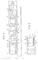
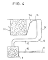
- FIGS. 1 to 4 are side views (FIGS. 3 and 4 only in the area upstream of the metering chamber) of devices according to the invention.
- the individual cavities and their interconnections are located between two plastic parts that can be assembled.
- the devices serve for flushing a substance located in a field d with a liquid detergent coming from a pump chamber PK in several flushing processes and for transferring the flushing agent emerging from the field d in the last flushing process into a cuvette K.
- the field d, the pump chamber PK and still further fields, chambers and lines to be described are located between the two joined plastic parts on a rotor R which can be rotated around the axis XX at a variable speed.
- the pump chamber PK is located radially within the field d between the two plastic parts on the rotor R.
- the pump chamber PK is emptied from the pump chamber PK above the predetermined speed under the action of the centrifugal force and emptied into the field d below the predetermined speed Valve chamber VK2 connected to field d.
- the field d is connected to the cuvette K via a line 4, which is directed in a section 6, the axis of which has a component pointing radially outwards, into a waste chamber AK.
- the pump chamber PK optionally merges at its radially inner end into a substrate elution chamber SK (FIG. 3) which is open at the top.
- a dosing chamber DK which fills the pump chamber PK with a predetermined volume of the detergent above a predetermined speed and transfers this volume of the detergent into the valve chamber VK2 below another predetermined speed.
- the metering chamber DK has an outlet capillary cap, the inlet 10 and outlet 12 of which are located radially outside the pump chamber PK, but whose inlet 10 is closer to the pump chamber PK than the outlet 12 thereof.
- the dosing chamber DK is connected to the pump chamber PK via a line 16 designed as a capillary tear-off throttle, the inlet of which is connected to a radially outer upper corner of the pump chamber PK.
- a space 50 which is not filled with fleece and has a larger cross section than the line 16.
- This space 50 is preferably connected to an air-supplying branch line 52, which forms a vacuum between the absorbent fleece in the pump chamber PK and the liquid in the dosing chamber DK prevented during the tear-off process.
- a line 26 leads from the outlet 12 via a capillary 22 into an overflow chamber ÜK.
- the line 26 is vented upwards through a line 28.
- the overflow chamber ÜK is connected to the valve chamber VK2 by a line 20.
- the valve chamber VK2 is connected to the field d by a line 32.
- the valve chamber VK2 is vented upwards through a branch line 34.
- Radially inside the valve chamber VK2 Radially from the inside out) are a field a with a sample application point P, a field b which is connected to the field a by two short connecting lines 38, 40, a valve chamber VK1 which is connected to the field b and is vented upwards through a branch line 42, and a field c which is connected to the valve chamber VK1 via an inlet line 44 and to the valve chamber VK2 via an outlet line 18.
- Field b and / or VK1 and field c can be omitted for simple reactions or uncritical reagents.
- the device for carrying out an immunological loading used according to the EIA principle using a bound phase.
- the bound phase which contains enzyme-labeled antibodies in the free form in the form of the antigen to be determined, is washed out with a substrate solution for the labeling enzyme serving as a washing liquid in several rinsing processes. This requires very short rinsing cycles and careful separation of the washing liquid from the portion of the substrate solution that serves as the measuring liquid during the last rinsing process.
- the pump chamber PK is filled with substrate solution or contains the substrate soaked on nonwovens.
- the advantage of using substrate dried on nonwovens lies in the better stability of the dry reagent compared to solutions and the easier storage of only one diluent for sample and substrate in the device. It is disadvantageous that when the substrate (+ buffer) is applied to the nonwovens of the pump chamber PK, a concentration gradient is formed when the diluent is added, which gradient cannot be broken down due to the existing nonwovens.
- This disadvantage is eliminated by connecting the substrate elution chamber SK upstream.
- This chamber SK is e.g. 3.5 mm deep and contains a substrate fleece of 1 mm thickness, on which the necessary amounts of substrate and buffer have been applied in a dried form in concentrated form.
- the chamber SK also contains e.g. iron disc E coated with plastic from e.g. about 0.5 mm thick, which can be moved by externally arranged magnets.
- the substrate and buffer are eluted from the fleece and the solution is completely homogenized.
- the substrate solution is conveyed into the pump chamber PK and partly into the metering chamber DK and then behaves like a liquid pipetted substrate solution. This allows the advantages of a homogeneous solution to be combined with those of better stability and diluent storage.
- the structure, handling and mode of operation of the device in this exemplary embodiment are as follows:
- a diluted sample is introduced into a fleece in field a and a diluent is introduced into a substrate-containing fleece in the pump chamber PK and the rotor R is circulated.
- the diluted sample dissolves the required amount of buffer from a buffer fleece in field b, reaches the first valve chamber VK1, is transferred from there to the conjugate fleece in field c by lowering the speed of the rotor R, dissolves out of this conjugate and arrives into the second valve chamber VK2, where an antigen + conjugate antibody-enzyme reaction takes place.
- the speed of the rotor R is reduced, the solution is sucked out of the valve chamber VK2 into a separating fleece in the field d and comes into contact with bound antibody there.
- the complexes antigen-conjugate AK-enzyme are bound here.
- the solution with the unbound conjugate is then thrown into the waste chamber AK.
- the diluent dissolves from the substrate-containing fleece in the pump chamber PK substrate.
- the substrate solution formed which serves as a washing liquid, arrives from there into the metering chamber DK, where precise metering takes place, then partly into the overflow chamber ÜK or directly into the second valve chamber VK2 and then to the separating fleece in the field d.
- the washing liquid is centrifuged from the separating fleece in the field d into the waste chamber AK in the doses determined by the dosing chamber DK, which are also referred to below as “sips”; if the waste chamber AK is filled, a portion of substrate solution is thrown into the cuvette K and measured there.
- the speed program of the rotor R looks something like this: For dosing each “sip”, the speed is first increased to such an extent that the liquid is thrown out of the fleece in the pump chamber PK against the capillary forces acting therein and transported via the tear-off throttle 16 into the dosing chamber DK becomes.
- the outlet capillary cap is initially only partially filled because in this state the capillary force in the radially inward part of the outlet capillary cap is smaller than the centrifugal force.
- the speed is then reduced to such an extent that the capillary force outweighs the centrifugal force in the radially inward part of the outlet capillary cape.
- the outlet capillary cap is sucked full, and at the same time the liquid connection between the metering chamber DK and the pump chamber PK breaks off in the region of the tear-off throttle 16.
- the outlet capillary cap is completely filled up to its outlet 12, where the liquid remains at the reduced speed mentioned. A certain volume of liquid is thus available in the dosing chamber DK and in the outlet capillary cape. This is emptied when the speed is increased again. Because the outlet 12 is located radially further out than the inlet 10, the outlet capillary cap acts like a siphon in the centrifugal force field. When increasing the speed, make sure that it is not so high that new liquid from the fleece in the pump chamber PK already reaches the dosing chamber DK. Rather, this may only be the case when the dosing chamber DK is emptied and the speed is increased again as described at the beginning to initiate a new dosing cycle.
- the capillary at the end of the capillary there should be an expanded cavity which is not filled with fleece and which prevents a spontaneous emptying of the capillary by capillary force.
- the capillary is only emptied when the centrifugal force is higher than the capillary force when the speed increases.
- the cavity at the end of the capillary also prevents liquid from flowing out of the adjoining fleece in the overflow chamber the general direction of transport can be sucked back.
- the dosing chamber DK and outlet capillary cap can also be emptied when the rotor R is at a standstill, since the radially inner side of the overflow chamber ÜK adjoins the outlet 12 of the capillary cap.
- a fleece in the overflow chamber ÜK sucks in the liquid coming from the dosing chamber DK as soon as it has filled the capillary cape.
- the capillary tear-off throttle 16 of the metering chamber DK towards the pump chamber PK must therefore have a very specific diameter, which is dependent on the surface properties of the substrate solution and the wall material.
- the overflow chamber ÜK preferably contains an absorbent medium, in particular paper, in order to fix a defined volume. It is also possible to provide an ordinary cavity which is connected via a capillary 22 to the outlet 12 of the dosing chamber DK. The liquid graft formed in such a capillary 22 then prevents a return of substrate solution from the overflow chamber ÜK into the outlet capillary cap of the dosing chamber DK. Preventing this backflow through an absorbent medium in the overflow chamber ÜK, however, proved to be better.
- the section 6 of the line 4 between the field d containing the separating fleece and the waste chamber AK must be such that no capillary forces are effective over its length. This is the only way to prevent fine droplets of the substrate solution that are to get into the waste chamber AK from bypassing the waste chamber AK and directly into the cuvette K.
- the surface of this section 6 is preferably provided with a Teflon scale covering. This is obtained using a Teflon spray that contains Teflon in an extremely fine form. In this way, tiny teflon scales form on the inner surface of section 6, which cause hydrophobization and at least prevent droplets from running back. Under certain conditions, an increased surface roughness of the inner surface may also be sufficient in this area.
- the device according to the invention creates in a disposable on a centrifugal analyzer the possibility of producing several sips of liquid, the volume of which is precisely defined, in particular exactly reproducible, without using any mechanical parts. This is particularly important for a disposable of the type described here because the total volume balance must be very accurate.
- the waste chamber in front of the cuvette must be filled in such a way that there is a quantity of liquid in it before the last washing step, which fills the chamber very precisely within relatively narrow tolerances, but does not overflow from the waste chamber.
- the tolerance of the filling of the waste chamber 1 is around 5%.
- the pump chamber is to be designed so large that its volume corresponds to a plurality of sips and with the help of the tear-off throttle, which interacts with the fleece contained in the pump chamber, it is possible to separate individual sags.
- a uniform fluid level (viewed in the radial direction) is generated in the pump chamber, in the metering chamber and in the outlet capillary.
- the outlet capillary extends radially inwards to such an extent that it cannot run out completely, ie radially further inwards than the highest liquid level in the pump chamber.
- the volume of the dosing chamber to the tear-off point and the corresponding partial volume of the outlet capillary therefore determine the size of the swallow.
- the opposing suction forces act on the one hand in the fleece of the pump chamber (these act against the general direction of liquid transport) and on the other hand in the outlet capillary (these act in the general direction of liquid transport).
- the force relationships are such that the capillary forces in the fleece are considerably greater than in the outlet capillary.
- the flow resistance of the tear-off throttle is determined in such a way that the moment at which the backflow begins, the tear-off takes place at the corresponding point.
- the pump chamber PK is connected to the metering chamber DK via a line 16 which is designed as a capillary tear-off throttle and has an expanded inlet section 16a.
- the pump chamber PK is of active capillary design and preferably contains a fleece for this purpose.
- the dosing chamber DK merges into an outlet channel RS in the area 10 without a recognizable transition.
- the outlet channel RS leads in the direction of the axis of rotation XX of the rotor R to a point which is closer to the axis of rotation XX than the surface of the liquid in the pump chamber PK during the rotation of the rotor R at a first increased speed and then leads radially from the axis of rotation XX away.
- the outlet channel RS leads through a chamber K, in which a suction fleece is located.
- the liquid cans which are discharged through the outlet channel RS are larger than in the exemplary embodiment described above, in which the outlet channel RS is capillary and is therefore designated by cap. Since, as mentioned above, the size of a sip is determined not only by the volume of the metering chamber, but also by the partial volume of the outlet channel that was filled during the first increased speed, the larger the cross section, the greater the differences in the volume of the individual sips of the outlet channel. For many applications, it is not a question of a particular uniformity of the doses, but only that the total dose from a plurality of doses is reproducibly the same with sufficient accuracy. The embodiment according to FIG. 4 is particularly suitable for such an application.
- the outlet channel RS is led out of the metering chamber DK in such a way that at least a part of it is located radially closer to the axis of rotation X-X of the rotor R than the liquid surface in the pump chamber PK during a rotation at a first increased speed.
- the liquid flows from the metering chamber only due to the force of gravity when the speed is reduced to a second, lower value. It is sucked up by the fleece in the chamber K.
- the outlet channel can also be designed here, as in FIG. 1, so that its outlet is located radially outward of the metering chamber.
Landscapes
- Immunology (AREA)
- Physics & Mathematics (AREA)
- Chemical & Material Sciences (AREA)
- Analytical Chemistry (AREA)
- Biochemistry (AREA)
- General Health & Medical Sciences (AREA)
- General Physics & Mathematics (AREA)
- Life Sciences & Earth Sciences (AREA)
- Pathology (AREA)
- Health & Medical Sciences (AREA)
- Centrifugal Separators (AREA)
- Automatic Analysis And Handling Materials Therefor (AREA)
- Investigating Or Analysing Biological Materials (AREA)
- Feeding, Discharge, Calcimining, Fusing, And Gas-Generation Devices (AREA)
- Treatment Of Fiber Materials (AREA)
- Detergent Compositions (AREA)
- Manufacturing Of Printed Wiring (AREA)
- Sampling And Sample Adjustment (AREA)
- Cleaning By Liquid Or Steam (AREA)
Claims (14)
Priority Applications (1)
| Application Number | Priority Date | Filing Date | Title |
|---|---|---|---|
| AT85108376T ATE43440T1 (de) | 1984-07-06 | 1985-07-05 | Vorrichtung zum durchspuelen einer in einem feld befindlichen substanz mit einem fluessigen spuelmittel in mehreren spuelvorgaengen und zur ueberfuehrung des beim letzten spuelvorgang aus dem feld austretenden spuelmittels in eine kuevette. |
Applications Claiming Priority (2)
| Application Number | Priority Date | Filing Date | Title |
|---|---|---|---|
| DE19843425009 DE3425009A1 (de) | 1984-07-06 | 1984-07-06 | Vorrichtung zum durchspuelen einer in einem feld befindlichen substanz mit einem fluessigen spuelmittel in mehreren spuelvorgaengen und zur ueberfuehrung des beim letzten spuelvorgang aus dem feld austretenden spuelmittels in eine kuevette |
| DE3425009 | 1984-07-06 |
Publications (3)
| Publication Number | Publication Date |
|---|---|
| EP0167175A2 EP0167175A2 (fr) | 1986-01-08 |
| EP0167175A3 EP0167175A3 (en) | 1987-09-30 |
| EP0167175B1 true EP0167175B1 (fr) | 1989-05-24 |
Family
ID=6240050
Family Applications (1)
| Application Number | Title | Priority Date | Filing Date |
|---|---|---|---|
| EP85108376A Expired EP0167175B1 (fr) | 1984-07-06 | 1985-07-05 | Dispositif pour le lavage d'une substance se trouvant dans un champ au moyen d'un fluide de lavage en plusieurs étapes de lavage et pour le transport dans une cuvette du fluide de lavage sortant dudit champ lors de la dernière étape de lavage |
Country Status (8)
| Country | Link |
|---|---|
| US (1) | US4915911A (fr) |
| EP (1) | EP0167175B1 (fr) |
| JP (1) | JPS6126859A (fr) |
| AT (1) | ATE43440T1 (fr) |
| AU (1) | AU563672B2 (fr) |
| DE (2) | DE3425009A1 (fr) |
| DK (1) | DK298685A (fr) |
| ES (1) | ES8701536A1 (fr) |
Cited By (1)
| Publication number | Priority date | Publication date | Assignee | Title |
|---|---|---|---|---|
| EP0326135B1 (fr) * | 1988-01-27 | 1993-03-31 | Roche Diagnostics GmbH | Toison de support pour des réactifs imprégnés détachables |
Families Citing this family (3)
| Publication number | Priority date | Publication date | Assignee | Title |
|---|---|---|---|---|
| US5242803A (en) * | 1987-07-17 | 1993-09-07 | Martin Marietta Energy Systems, Inc. | Rotor assembly and assay method |
| US5173262A (en) * | 1987-07-17 | 1992-12-22 | Martin Marietta Energy Systems, Inc. | Rotor assembly and method for automatically processing liquids |
| US4985631A (en) * | 1988-02-16 | 1991-01-15 | Wannlund Jon C | Luminescence exposure apparatus |
Family Cites Families (9)
| Publication number | Priority date | Publication date | Assignee | Title |
|---|---|---|---|---|
| US3801004A (en) * | 1972-09-22 | 1974-04-02 | Union Carbide Corp | Device for collecting the contents of cuvets in a rotating spectrophotometer analyzer |
| US3890101A (en) * | 1974-02-15 | 1975-06-17 | Us Energy | Collection ring for use in multiple-sample blood fractionation centrifugal rotors |
| US3899296A (en) * | 1974-07-17 | 1975-08-12 | Us Energy | Whole blood analysis rotor for a multistation dynamic photometer |
| US4284602A (en) * | 1979-12-10 | 1981-08-18 | Immutron, Inc. | Integrated fluid manipulator |
| CA1152353A (fr) * | 1980-05-05 | 1983-08-23 | Georges Revillet | Rotor multicuvette pour analyseur |
| DE3044372A1 (de) * | 1980-11-25 | 1982-07-08 | Boehringer Mannheim Gmbh, 6800 Mannheim | Rotoreinheit mit einsatzelementen fuer einen zentrifugalanalysator |
| DE3044385A1 (de) * | 1980-11-25 | 1982-06-24 | Boehringer Mannheim Gmbh, 6800 Mannheim | Verfahren zur durchfuehrung analytischer bestimmungen und hierfuer geeignetes rotoreinsatzelement |
| DE3134560A1 (de) * | 1981-09-01 | 1983-03-17 | Boehringer Mannheim Gmbh, 6800 Mannheim | Vorrichtung und verfahren zum steuern und mischen einer der zentrifugalkraft ausgesetzten fluessigkeitsstroemung |
| IT1169162B (it) * | 1983-02-07 | 1987-05-27 | Azionaria Costruzioni Acma Spa | Alimentazione di prodotti del tipo dei saponi, per macchina ricevitrice a moto continuo |
-
1984
- 1984-07-06 DE DE19843425009 patent/DE3425009A1/de not_active Withdrawn
-
1985
- 1985-06-28 AU AU44431/85A patent/AU563672B2/en not_active Expired - Fee Related
- 1985-07-01 DK DK298685A patent/DK298685A/da not_active Application Discontinuation
- 1985-07-04 JP JP14594585A patent/JPS6126859A/ja active Granted
- 1985-07-05 AT AT85108376T patent/ATE43440T1/de not_active IP Right Cessation
- 1985-07-05 EP EP85108376A patent/EP0167175B1/fr not_active Expired
- 1985-07-05 DE DE8585108376T patent/DE3570524D1/de not_active Expired
- 1985-07-05 ES ES544889A patent/ES8701536A1/es not_active Expired
-
1987
- 1987-09-21 US US07/098,780 patent/US4915911A/en not_active Expired - Fee Related
Cited By (1)
| Publication number | Priority date | Publication date | Assignee | Title |
|---|---|---|---|---|
| EP0326135B1 (fr) * | 1988-01-27 | 1993-03-31 | Roche Diagnostics GmbH | Toison de support pour des réactifs imprégnés détachables |
Also Published As
| Publication number | Publication date |
|---|---|
| JPH0481743B2 (fr) | 1992-12-24 |
| US4915911A (en) | 1990-04-10 |
| ATE43440T1 (de) | 1989-06-15 |
| ES544889A0 (es) | 1986-12-16 |
| DK298685D0 (da) | 1985-07-01 |
| AU4443185A (en) | 1986-01-09 |
| JPS6126859A (ja) | 1986-02-06 |
| DE3425009A1 (de) | 1986-02-06 |
| EP0167175A3 (en) | 1987-09-30 |
| AU563672B2 (en) | 1987-07-16 |
| DE3570524D1 (en) | 1989-06-29 |
| EP0167175A2 (fr) | 1986-01-08 |
| DK298685A (da) | 1986-01-07 |
| ES8701536A1 (es) | 1986-12-16 |
Similar Documents
| Publication | Publication Date | Title |
|---|---|---|
| EP0039825B1 (fr) | Rotor à cuvettes pour appareil d'analyse et procédé pour l'operation dudit rotor à cuvettes | |
| EP0073512B1 (fr) | Dispositif et procédé pour contrôler et mélanger un liquide exposé à une force centrifuge | |
| EP2072131B1 (fr) | Elément microfluide destiné au mélange d'un liquide dans un réactif | |
| DE60035611T2 (de) | Mikrofluid-analysevorrichtung | |
| DE60132198T2 (de) | Plattentrenneinrichtung für blutbestandteile | |
| DE3134611A1 (de) | Verfahren zur durchfuehrung analytischer bestimmungen und hierfuer geeignetes mittel | |
| EP2506959B1 (fr) | Elément micro-fluidique destiné à l'analyse d'un échantillon de liquide | |
| EP2632591B1 (fr) | Élément microfluidique pour l'analyse d'un échantillon liquide | |
| DE69737619T2 (de) | Waschgerät für automatische Analysevorrichtung | |
| EP3592463B1 (fr) | Procédé de commutation centrifugo-pneumatique de liquide | |
| DE2336619C2 (de) | Photometrischer Analysator | |
| EP2428272B1 (fr) | Procédé de revêtement hyrophobe d'embouts de pipette | |
| EP1474235A1 (fr) | Dispositif de preparation d'echantillons et appareillage d'essai faisant appel a ce dernier | |
| DE10015380A1 (de) | Mikrofluidkomponente und Verfahren zur Oberflächenbehandlung einer solchen | |
| DE2523513A1 (de) | Reaktionsbehaelter fuer chemische analysen | |
| DE2117423B2 (de) | Probentraeger- und transportvorrichtung | |
| EP0167175B1 (fr) | Dispositif pour le lavage d'une substance se trouvant dans un champ au moyen d'un fluide de lavage en plusieurs étapes de lavage et pour le transport dans une cuvette du fluide de lavage sortant dudit champ lors de la dernière étape de lavage | |
| EP3263215B1 (fr) | Dispositif comprenant un cellule comprenant un dispositif de stockage de reactif | |
| DE1815502C3 (de) | Verfahren und Vorrichtung zum Mischen und Umfüllen einer Probeflüssigkeit | |
| DE102011079698B4 (de) | Mikrofluidische Vorrichtung mit einer Kammer zur Lagerung einer Flüssigkeit | |
| DE102021208891B3 (de) | Unterdruckschalten von Flüssigkeit | |
| DE3703189C2 (fr) | ||
| EP3329993A1 (fr) | Récipient porte-échantillon destiné à recevoir des échantillons liquides de petit volume | |
| DE20321610U1 (de) | Probenvorbereitungsvorrichtung und hierauf aufbauender Testgerätesatz | |
| DE102013019653B3 (de) | Vorrichtung und Verfahren, um logarithmischen Testaufwand bei Reihentestung flüssiger oder gasförmiger Proben zu erreichen |
Legal Events
| Date | Code | Title | Description |
|---|---|---|---|
| PUAI | Public reference made under article 153(3) epc to a published international application that has entered the european phase |
Free format text: ORIGINAL CODE: 0009012 |
|
| 17P | Request for examination filed |
Effective date: 19850705 |
|
| AK | Designated contracting states |
Designated state(s): AT BE CH DE FR GB IT LI LU NL SE |
|
| PUAL | Search report despatched |
Free format text: ORIGINAL CODE: 0009013 |
|
| AK | Designated contracting states |
Kind code of ref document: A3 Designated state(s): AT BE CH DE FR GB IT LI LU NL SE |
|
| 17Q | First examination report despatched |
Effective date: 19880222 |
|
| GRAA | (expected) grant |
Free format text: ORIGINAL CODE: 0009210 |
|
| AK | Designated contracting states |
Kind code of ref document: B1 Designated state(s): AT BE CH DE FR GB IT LI LU NL SE |
|
| PG25 | Lapsed in a contracting state [announced via postgrant information from national office to epo] |
Ref country code: SE Effective date: 19890524 Ref country code: NL Effective date: 19890524 Ref country code: IT Free format text: LAPSE BECAUSE OF FAILURE TO SUBMIT A TRANSLATION OF THE DESCRIPTION OR TO PAY THE FEE WITHIN THE PRESCRIBED TIME-LIMIT;WARNING: LAPSES OF ITALIAN PATENTS WITH EFFECTIVE DATE BEFORE 2007 MAY HAVE OCCURRED AT ANY TIME BEFORE 2007. THE CORRECT EFFECTIVE DATE MAY BE DIFFERENT FROM THE ONE RECORDED. Effective date: 19890524 Ref country code: BE Effective date: 19890524 |
|
| REF | Corresponds to: |
Ref document number: 43440 Country of ref document: AT Date of ref document: 19890615 Kind code of ref document: T |
|
| GBT | Gb: translation of ep patent filed (gb section 77(6)(a)/1977) | ||
| REF | Corresponds to: |
Ref document number: 3570524 Country of ref document: DE Date of ref document: 19890629 |
|
| PG25 | Lapsed in a contracting state [announced via postgrant information from national office to epo] |
Ref country code: AT Effective date: 19890705 |
|
| PG25 | Lapsed in a contracting state [announced via postgrant information from national office to epo] |
Ref country code: LU Free format text: LAPSE BECAUSE OF NON-PAYMENT OF DUE FEES Effective date: 19890731 Ref country code: LI Effective date: 19890731 Ref country code: CH Effective date: 19890731 |
|
| ET | Fr: translation filed | ||
| NLV1 | Nl: lapsed or annulled due to failure to fulfill the requirements of art. 29p and 29m of the patents act | ||
| PLBE | No opposition filed within time limit |
Free format text: ORIGINAL CODE: 0009261 |
|
| STAA | Information on the status of an ep patent application or granted ep patent |
Free format text: STATUS: NO OPPOSITION FILED WITHIN TIME LIMIT |
|
| REG | Reference to a national code |
Ref country code: CH Ref legal event code: PL |
|
| 26N | No opposition filed | ||
| PGFP | Annual fee paid to national office [announced via postgrant information from national office to epo] |
Ref country code: GB Payment date: 19910624 Year of fee payment: 7 |
|
| PG25 | Lapsed in a contracting state [announced via postgrant information from national office to epo] |
Ref country code: GB Effective date: 19920705 |
|
| GBPC | Gb: european patent ceased through non-payment of renewal fee |
Effective date: 19920705 |
|
| PGFP | Annual fee paid to national office [announced via postgrant information from national office to epo] |
Ref country code: DE Payment date: 20010625 Year of fee payment: 17 |
|
| PGFP | Annual fee paid to national office [announced via postgrant information from national office to epo] |
Ref country code: FR Payment date: 20010712 Year of fee payment: 17 |
|
| PG25 | Lapsed in a contracting state [announced via postgrant information from national office to epo] |
Ref country code: DE Free format text: LAPSE BECAUSE OF NON-PAYMENT OF DUE FEES Effective date: 20030201 |
|
| PG25 | Lapsed in a contracting state [announced via postgrant information from national office to epo] |
Ref country code: FR Free format text: LAPSE BECAUSE OF NON-PAYMENT OF DUE FEES Effective date: 20030331 |
|
| REG | Reference to a national code |
Ref country code: FR Ref legal event code: ST |