EP0167175B1 - Device for washing a substance present in a field with a washing liquid in several washing steps and for transporting the washing fluid, emerging from said field, after the last washing step to a cuvette - Google Patents
Device for washing a substance present in a field with a washing liquid in several washing steps and for transporting the washing fluid, emerging from said field, after the last washing step to a cuvette Download PDFInfo
- Publication number
- EP0167175B1 EP0167175B1 EP85108376A EP85108376A EP0167175B1 EP 0167175 B1 EP0167175 B1 EP 0167175B1 EP 85108376 A EP85108376 A EP 85108376A EP 85108376 A EP85108376 A EP 85108376A EP 0167175 B1 EP0167175 B1 EP 0167175B1
- Authority
- EP
- European Patent Office
- Prior art keywords
- chamber
- block
- washing
- capillary
- radially
- Prior art date
- Legal status (The legal status is an assumption and is not a legal conclusion. Google has not performed a legal analysis and makes no representation as to the accuracy of the status listed.)
- Expired
Links
Images

Classifications
-
- G—PHYSICS
- G01—MEASURING; TESTING
- G01N—INVESTIGATING OR ANALYSING MATERIALS BY DETERMINING THEIR CHEMICAL OR PHYSICAL PROPERTIES
- G01N21/00—Investigating or analysing materials by the use of optical means, i.e. using sub-millimetre waves, infrared, visible or ultraviolet light
- G01N21/01—Arrangements or apparatus for facilitating the optical investigation
- G01N21/03—Cuvette constructions
- G01N21/07—Centrifugal type cuvettes
-
- B—PERFORMING OPERATIONS; TRANSPORTING
- B01—PHYSICAL OR CHEMICAL PROCESSES OR APPARATUS IN GENERAL
- B01L—CHEMICAL OR PHYSICAL LABORATORY APPARATUS FOR GENERAL USE
- B01L3/00—Containers or dishes for laboratory use, e.g. laboratory glassware; Droppers
- B01L3/50—Containers for the purpose of retaining a material to be analysed, e.g. test tubes
- B01L3/502—Containers for the purpose of retaining a material to be analysed, e.g. test tubes with fluid transport, e.g. in multi-compartment structures
- B01L3/5027—Containers for the purpose of retaining a material to be analysed, e.g. test tubes with fluid transport, e.g. in multi-compartment structures by integrated microfluidic structures, i.e. dimensions of channels and chambers are such that surface tension forces are important, e.g. lab-on-a-chip
Abstract
Description
Die Erfindung betrifft eine Vorrichtung nach dem Oberbegriff des Anspruchs 1.The invention relates to a device according to the preamble of
Aufgabe der Erfindung ist es, eine Vorrichtung dieser Art derart auszubilden, dass sie für den Flüssigkeitstransport keiner inneren beweglichen Teile bedarf und in ihrer Wirkungsweise durch Veränderung eines einzigen Parameters steuerbar ist.The object of the invention is to design a device of this type such that it does not require any internal moving parts for the liquid transport and its mode of operation can be controlled by changing a single parameter.
Die Lösung dieser Aufgabe ist im Kennzeichen des Anspruchs 1 angegeben.The solution to this problem is specified in the characterizing part of
Ersichtlich hat die Vorrichtung keine inneren beweglichen Teile. Der einzige zu steuernde Parameter ist die Drehzahl des Rotors.Obviously the device has no internal moving parts. The only parameter to be controlled is the speed of the rotor.
Ventilkammern im Sinne der vorliegenden Anmeldung sind in der Europäischen Patentanmeldung EP-A 0073512 beschrieben und dort «Mischventil» genannt. Eine Beschreibung von Aufbau und Wirkungsweise dieser Ventilkammern ist daher hier nicht erforderlich. Vielmehr wird auf die Europäische Patentanmeldung EP-A 0073512 Bezug genommen und deren Offenbarungsgehalt zum Offenbarungsgehalt vorliegender Anmeldung gemacht.Valve chambers in the sense of the present application are described in the European patent application EP-A 0073512 and called "mixing valve" there. A description of the structure and mode of operation of these valve chambers is therefore not necessary here. Rather, reference is made to the European patent application EP-A 0073512 and its disclosure content is made the disclosure content of the present application.
Besondere Ausführungsarten der Erfindung sind in den abhängigen Ansprüchen 2-14 angegeben.Particular embodiments of the invention are specified in dependent claims 2-14.
Die Bedeutung der Unteransprüche ergibt sich aus der nachfolgenden Beschreibung eines Ausführungsbeispiels.The meaning of the subclaims results from the following description of an embodiment.
Die Funktion der Vorrichtung wird auch durch ihre Grenzflächeneigenschaften und Oberflächenbeschaffenheit beeinflusst. Diese Grenzflächeneigenschaften können durch Zusatz oberflächenaktiver Mittel, beispielsweise von Detergenzien, zur Flüssigkeit, zu den Vliesen oder zur Vorrichtung, beeinflusst werden.The function of the device is also influenced by its interface properties and surface properties. These interface properties can be influenced by adding surface-active agents, for example detergents, to the liquid, to the nonwovens or to the device.
Die Oberflächenbeschaffenheit kann beispielsweise durch Beschichten mit hydrophoben oder hydrophilen Materialien, Bestrahlen oder Aufrauhen verändert werden.The surface quality can be changed, for example, by coating with hydrophobic or hydrophilic materials, irradiation or roughening.
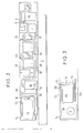
In den beigefügten Zeichnungen sind in den Fig. 1 bis 4 Seitenansichten (Fig. 3 und 4 nur im Bereich stromaufwärts der Dosierkammer) erfindungsgemässer Vorrichtungen dargestellt. Die einzelnen Hohlräume und ihre Verbindungen untereinander befinden sich zwischen zwei zusammensetzbaren Kunststoffteilen.In the accompanying drawings, FIGS. 1 to 4 are side views (FIGS. 3 and 4 only in the area upstream of the metering chamber) of devices according to the invention. The individual cavities and their interconnections are located between two plastic parts that can be assembled.
Die Vorrichtungen dienen zum Durchspülen einer in einem Feld d befindlichen Substanz mit einem aus einer Pumpenkammer PK kommenden flüssigen Spülmittel in mehreren Spülvorgängen und zur Überführung des beim letzten Spülvorgang aus dem Feld d austretenden Spülmittels in eine Küvette K. Das Feld d, die Pumpenkammer PK und noch weitere zu beschreibende Felder, Kammern und Leitungen befinden sich zwischen den beiden zusammengefügten Kunststoffteilen auf einem Rotor R, der mit veränderbarer Drehzahl um die Achse X-X zu drehen ist. Die Pumpenkammer PK befindet sich radial innerhalb des Feldes d zwischen den beiden Kunststoffteilen auf dem Rotor R. Die Pumpenkammer PK ist über eine sich unter der Wirkung der Zentrifugalkraft oberhalb einer vorgegebenen Drehzahl aus der Pumpenkammer PK füllende und unterhalb der vorgegebenen Drehzahl in das Feld d entleerende Ventilkammer VK2 mit dem Feld d verbunden. Das Feld d ist mit der Küvette K über eine Leitung 4 verbunden, die in einem Abschnitt 6, dessen Achse eine radial nach aussen weisende Komponente hat, in eine Abfallkammer AK gerichtet ist.The devices serve for flushing a substance located in a field d with a liquid detergent coming from a pump chamber PK in several flushing processes and for transferring the flushing agent emerging from the field d in the last flushing process into a cuvette K. The field d, the pump chamber PK and still further fields, chambers and lines to be described are located between the two joined plastic parts on a rotor R which can be rotated around the axis XX at a variable speed. The pump chamber PK is located radially within the field d between the two plastic parts on the rotor R. The pump chamber PK is emptied from the pump chamber PK above the predetermined speed under the action of the centrifugal force and emptied into the field d below the predetermined speed Valve chamber VK2 connected to field d. The field d is connected to the cuvette K via a
Die Pumpenkammer PK geht gegebenenfalls an ihrem radial inneren Ende oben in eine nach oben offene Substratelutionskammer SK (Fig. 3) über. Zwischen der Pumpenkammer PK und der Ventilkammer VK2 ist eine sich oberhalb einer vorgegebenen Drehzahl aus der Pumpenkammer PK mit einem vorgegebenen Volumen des Spülmittels füllende und unterhalb einer anderen vorgegebenen Drehzahl dieses Volumen des Spülmittels in die Ventilkammer VK2 überführende Dosierkammer DK geschaltet. Die Dosierkammer DK weist eine Auslaufkapillare Kap auf, deren Einlass 10 und Auslass 12 radial ausserhalb der Pumpenkammer PK liegen, deren Einlass 10 jedoch näher an der Pumpenkammer PK liegt als deren Auslass 12.The pump chamber PK optionally merges at its radially inner end into a substrate elution chamber SK (FIG. 3) which is open at the top. Between the pump chamber PK and the valve chamber VK2 there is connected a dosing chamber DK which fills the pump chamber PK with a predetermined volume of the detergent above a predetermined speed and transfers this volume of the detergent into the valve chamber VK2 below another predetermined speed. The metering chamber DK has an outlet capillary cap, the
Die Dosierkammer DK ist mit der Pumpenkammer PK über eine als kapillare Abreissdrossel ausgebildete Leitung 16 verbunden, deren Einlass an eine radial äussere obere Ecke der Pumpenkammer PK angeschlossen ist.The dosing chamber DK is connected to the pump chamber PK via a
Zwischen einem Vlies in der Pumpenkammer PK und der als kapillare Abreissdrossel ausgebildeten Leitung 16 befindet sich vorzugsweise ein nicht mit Vlies gefüllter Raum 50 von grösserem Querschnitt als die Leitung 16. Dieser Raum 50 ist bevorzugt mit einer luftzuführenden Stichleitung 52 verbunden, die eine Unterdruckbildung zwischen dem saugenden Vlies in der Pumpenkammer PK und der Flüssigkeit in der Dosierkammer DK beim Abreissvorgang verhindert.Between a fleece in the pump chamber PK and the
Von dem Auslass 12 führt nach Fig. 1 eine Leitung 26 über eine Kapillare 22 in eine Überlaufkammer ÜK. Die Leitung 26 ist nach oben hin durch eine Leitung 28 entlüftet.According to FIG. 1, a
Die Überlaufkammer ÜK ist mit der Ventilkammer VK2 durch eine Leitung 20 verbunden.The overflow chamber ÜK is connected to the valve chamber VK2 by a
Die Ventilkammer VK2 ist mit dem Feld d durch eine Leitung 32 verbunden. Nach oben hin ist die Ventilkammer VK2 durch eine Stichleitung 34 entlüftet. Radial innerhalb der Ventilkammer VK2 liegen (radial von innen nach aussen) ein Feld a mit einer Probenauftragstelle P, ein Feld b, das mit dem Feld a durch zwei kurze Verbindungsleitungen 38, 40 verbunden ist, eine Ventilkammer VK1, die mit dem Feld b verbunden und nach oben hin durch eine Stichleitung 42 entlüftet ist, sowie ein Feld c, das über eine Einlassleitung 44 mit der Ventilkammer VK1 und über eine Auslassleitung 18 mit der Ventilkammer VK2 verbunden ist.The valve chamber VK2 is connected to the field d by a
Für einfache Reaktionen bzw. unkritische Reagenzien kann auf das Feld b und/oder VK1 und Feld c verzichtet werden.Field b and / or VK1 and field c can be omitted for simple reactions or uncritical reagents.
Bei dem im folgenden beschriebenen bevorzugten Ausführungsbeispiel wird die Vorrichtung zur Durchführung einer immunologischen Bestimmung nach dem EIA-Prinzip unter Verwendung einer gebundenen Phase benutzt. Die gebundene Phase, welche enzymmarkierten Antikörper in über zu bestimmendes Antigen gebundener und in freier Form enthält, wird mit einer als Waschflüssigkeit dienenden Substratlösung für das Markierungsenzym in mehreren Spülvorgängen ausgewaschen. Dies erfordert sehr kurze Spülzyklen und eine sorgfältige Trennung der Waschflüssigkeit von dem Anteil der Substratlösung, der beim letzten Spülvorgang als Messflüssigkeit dient.In the preferred embodiment described below, the device for carrying out an immunological loading used according to the EIA principle using a bound phase. The bound phase, which contains enzyme-labeled antibodies in the free form in the form of the antigen to be determined, is washed out with a substrate solution for the labeling enzyme serving as a washing liquid in several rinsing processes. This requires very short rinsing cycles and careful separation of the washing liquid from the portion of the substrate solution that serves as the measuring liquid during the last rinsing process.
Die Pumpenkammer PK wird mit Substratlösung gefüllt oder enthält das Substrat getränkt auf Vliesen. Der Vorteil der Verwendung von Substrat getrocknet auf Vliesen liegt in der besseren Stabilität des Trockenreagenzes gegenüber Lösungen und der einfacheren Bevorratung von nur einem Diluens für Probe und Substrat in der Vorrichtung. Nachteilig ist, dass bei Aufbringung des Substrats (+Puffer) auf die Vliese der Pumpenkammer PK sich bei Zugabe des Diluens ein Konzentrationsgradient bildet, der wegen der vorhandenen Vliese nicht abgebaut werden kann.The pump chamber PK is filled with substrate solution or contains the substrate soaked on nonwovens. The advantage of using substrate dried on nonwovens lies in the better stability of the dry reagent compared to solutions and the easier storage of only one diluent for sample and substrate in the device. It is disadvantageous that when the substrate (+ buffer) is applied to the nonwovens of the pump chamber PK, a concentration gradient is formed when the diluent is added, which gradient cannot be broken down due to the existing nonwovens.
Dieser Nachteil wird beseitigt durch Vorschalten der Substratelutionskammer SK. Diese Kammer SK ist z.B. 3,5 mm tief und enthält ein Substratvlies von 1 mm Dicke, auf dem in konzentrierter Form die nötigen Mengen Substrat und Puffer in getrockneter Form aufgebracht wurden. Die Kammer SK enthält ferner eine z.B. mit Kunststoff beschichtete Eisenscheibe E von z.B. etwa 0,5 mm Dicke, die durch extern angeordnete Magnete bewegt werden kann. Nach Zugabe von Diluens (Aufgabestelle (5)) wird eine Elution von Substrat und Puffer vom Vlies erreicht sowie eine völlige Homogenisierung der Lösung. Bei der ersten Zentrifugation wird die Substratlösung in die Pumpenkammer PK und teils in die Dosierkammer DK befördert und verhält sich danach wie eine flüssige pipettierte Substratlösung. Dadurch können die Vorteile einer homogenen Lösung mit denen der besseren Stabilität und Diluens-Bevorratung verbunden werden.This disadvantage is eliminated by connecting the substrate elution chamber SK upstream. This chamber SK is e.g. 3.5 mm deep and contains a substrate fleece of 1 mm thickness, on which the necessary amounts of substrate and buffer have been applied in a dried form in concentrated form. The chamber SK also contains e.g. iron disc E coated with plastic from e.g. about 0.5 mm thick, which can be moved by externally arranged magnets. After adding diluent (application point (5)), the substrate and buffer are eluted from the fleece and the solution is completely homogenized. During the first centrifugation, the substrate solution is conveyed into the pump chamber PK and partly into the metering chamber DK and then behaves like a liquid pipetted substrate solution. This allows the advantages of a homogeneous solution to be combined with those of better stability and diluent storage.
Aufbau, Handhabung und Wirkungsweise der Vorrichtung sind in diesem Ausführungsbeispiel wie folgt:The structure, handling and mode of operation of the device in this exemplary embodiment are as follows:
Eine verdünnte Probe wird in ein Vlies in dem Feld a und ein Verdünnungsmittel wird in ein substrathaltiges Vlies in der Pumpenkammer PK eingeführt und der Rotor R in Umlauf gesetzt. Die verdünnte Probe löst aus einem Puffervlies in dem Feld b die erforderliche Puffermenge heraus, gelangt in die erste Ventilkammer VK1, wird von dort aus durch Senkung der Drehzahl des Rotors R in ein Konjugatvlies in dem Feld c überführt, löst aus diesem Konjugat heraus und gelangt in die zweite Ventilkammer VK2, wo eine Reaktion Antigen+Konjugat Antikörper-Enzym abläuft. Bei Herabsetzen der Drehzahl des Rotors R wird die Lösung aus der Ventilkammer VK2 in ein Trennvlies in dem Feld d gesaugt und kommt dort mit gebundenem Antikörper in Berührung. Hier werden die Komplexe Antigen-Konjugat AK-Enzym gebunden. Danach wird die Lösung mit dem nicht gebundenen Konjugat in die Abfallkammer AK geschleudert. Parallel dazu löst das Verdünnungsmittel aus dem substrathaltigen Vlies in der Pumpenkammer PK Substrat heraus. Die gebildete Substratlösung, die als Waschflüssigkeit dient, gelangt von dort in die Dosierkammer DK, wo eine genaue Dosierung erfolgt, dann teilweise in die Überlaufkammer ÜK oder direkt in die zweite Ventilkammer VK2 und dann zum Trennvlies in dem Feld d. Durch periodische Beschleunigung und Verzögerung des Rotors R wird die Waschflüssigkeit in den durch die Dosierkammer DK festgelegten Dosen, die im folgenden auch als «Schlucke» bezeichnet werden, aus dem Trennvlies in dem Feld d in die Abfallkammer AK zentrifugiert; ist die Abfallkammer AK gefüllt, wird eine Portion Substratlösung in die Küvette K geschleudert und dort gemessen.A diluted sample is introduced into a fleece in field a and a diluent is introduced into a substrate-containing fleece in the pump chamber PK and the rotor R is circulated. The diluted sample dissolves the required amount of buffer from a buffer fleece in field b, reaches the first valve chamber VK1, is transferred from there to the conjugate fleece in field c by lowering the speed of the rotor R, dissolves out of this conjugate and arrives into the second valve chamber VK2, where an antigen + conjugate antibody-enzyme reaction takes place. When the speed of the rotor R is reduced, the solution is sucked out of the valve chamber VK2 into a separating fleece in the field d and comes into contact with bound antibody there. The complexes antigen-conjugate AK-enzyme are bound here. The solution with the unbound conjugate is then thrown into the waste chamber AK. At the same time, the diluent dissolves from the substrate-containing fleece in the pump chamber PK substrate. The substrate solution formed, which serves as a washing liquid, arrives from there into the metering chamber DK, where precise metering takes place, then partly into the overflow chamber ÜK or directly into the second valve chamber VK2 and then to the separating fleece in the field d. By periodically accelerating and decelerating the rotor R, the washing liquid is centrifuged from the separating fleece in the field d into the waste chamber AK in the doses determined by the dosing chamber DK, which are also referred to below as “sips”; if the waste chamber AK is filled, a portion of substrate solution is thrown into the cuvette K and measured there.
Das Drehzahlprogramm des Rotors R sieht etwa so aus: Zur Dosierung jedes «Schlucks» wird zunächst die Drehzahl soweit erhöht, dass die Flüssigkeit aus dem in der Pumpenkammer PK befindlichen Vlies gegen die darin wirkenden Kapillarkräfte herausgeschleudert und über die Abreissdrossel 16 in die Dosierkammer DK transportiert wird. Dabei füllt sich die Auslaufkapillare Kap zunächst nur teilweise, weil in diesem Zustand die Kapillarkraft in dem nach radial innen gerichteten Teil der Auslaufkapillare Kap kleiner ist als die Zentrifugalkraft. Danach wird die Drehzahl soweit abgesenkt, dass in dem nach radial innen gerichteten Teil der Auslaufkapillare Kap die Kapillarkraft gegenüber der Zentrifugalkraft überwiegt. Dadurch wird die Auslaufkapillare Kap vollgesaugt, und gleichzeitig reisst die Flüssigkeitsverbindung zwischen der Dosierkammer DK und der Pumpenkammer PK im Bereich der Abreissdrossel 16 ab. Die Auslaufkapillare Kap füllt sich vollständig bis an ihren Auslass 12, wo die Flüssigkeit bei der erwähnten abgesenkten Drehzahl stehen bleibt. Somit steht in der Dosierkammer DK und in der Auslaufkapillare Kap ein bestimmtes Volumen an Flüssigkeit bereit. Dieses wird entleert, wenn man die Drehzahl erneut erhöht. Da nämlich der Auslass 12 radial weiter aussen liegt als der Einlass 10, wirkt die Auslaufkapillare Kap siphonartig im Zentrifugalkraftfeld. Bei dieser Drehzahlerhöhung ist darauf zu achten, dass sie nicht so hoch ist, dass bereits neue Flüssigkeit aus dem Vlies in der Pumpenkammer PK heraus in die Dosierkammer DK gelangt. Dies darf vielmehr erst der Fall sein, wenn die Dosierkammer DK entleert ist und zur Einleitung eines neuen Dosierzyklus die Drehzahl erneut wie anfangs beschrieben erhöht wird.The speed program of the rotor R looks something like this: For dosing each “sip”, the speed is first increased to such an extent that the liquid is thrown out of the fleece in the pump chamber PK against the capillary forces acting therein and transported via the tear-off
Bei der Ausführungsform nach Fig. 1 sollte am Ende der Kapillare ein nicht mit Vlies gefüllter, erweiterter Hohlraum vorhanden sein, der eine spontane Entleerung der Kapillare durch Kapillarkraft verhindert. Die Kapillare entleert sich dann erst, wenn bei Erhöhung der Drehzahl die Zentrifugalkraft höher ist als die Kapillarkraft. Der Hohlraum am Ende der Kapillare verhindert ausserdem, dass aus dem sich anschliessenden Vlies in der Überlaufkammer Flüssigkeit gegen die allgemeine Transportrichtung zurückgesaugt werden kann.In the embodiment according to FIG. 1, at the end of the capillary there should be an expanded cavity which is not filled with fleece and which prevents a spontaneous emptying of the capillary by capillary force. The capillary is only emptied when the centrifugal force is higher than the capillary force when the speed increases. The cavity at the end of the capillary also prevents liquid from flowing out of the adjoining fleece in the overflow chamber the general direction of transport can be sucked back.
Bei der Ausführungsform nach Fig. 2 kann eine Entleerung von Dosierkammer DK und Auslaufkapillare Kap auch im Stillstand des Rotors R erfolgen, da die radial innere Seite der Überlaufkammer ÜK an den Auslass 12 der Kapillare Kap angrenzt. Ein Vlies in der Überlaufkammer ÜK saugt die aus der Dosierkammer DK kommende Flüssigkeit an, sobald sie die Kapillare Kap gefüllt hat. Bei einer solchen Ausführungsform ist es nicht notwendig, dass der Auslass der Kapillare Kap radial weiter auswärts als ihr Einlass liegt. Besonders vorteilhaft ist bei dieser Ausführungsform, dass bei niedriger Drehzahl des Rotors R die noch durchlaufenden «Schlucke» zurückgehalten werden.In the embodiment according to FIG. 2, the dosing chamber DK and outlet capillary cap can also be emptied when the rotor R is at a standstill, since the radially inner side of the overflow chamber ÜK adjoins the
Wichtig ist, dass die Flüssigkeitsäule in der Dosierkammer DK, welche z.B. exakt 29 !J.I Flüssigkeit fasst, zur Pumpenkammer PK hin sauber ab- . reisst. Die kapillare Abreissdrossel 16 der Dosierkammer DK zur Pumpenkammer PK hin muss daher einen ganz bestimmten Durchmesser aufweisen, der von den Oberflächeneigenschaften der Substratlösung und des Wandmaterials abhängig ist.It is important that the liquid column in the dosing chamber DK, which e.g. exactly 29! J.I holds liquid, cleanly towards the pump chamber PK. tears. The capillary tear-
Die Überlaufkammer ÜK enthält bevorzugt ein saugfähiges Medium, insbesondere Papier, um ein definiertes Volumen zu fixieren. Es ist auch möglich, einen gewöhnlichen Hohlraum vorzusehen, der über eine Kapillare 22 mit dem Auslass 12 der Dosierkammer DK verbunden ist. Der in einer solchen Kapillare 22 sich bildende Flüssigkeitspfropf verhindert dann einen Rücklauf von Substratlösung aus der Überlaufkammer ÜK in die Auslaufkapillare Kap der Dosierkammer DK. Eine Verhinderung dieses Rücklaufs durch ein saugfähiges Medium in der Überlaufkammer ÜK erwies sich jedoch als besser.The overflow chamber ÜK preferably contains an absorbent medium, in particular paper, in order to fix a defined volume. It is also possible to provide an ordinary cavity which is connected via a capillary 22 to the
Der Abschnitt 6 der Leitung 4 zwischen dem das Trennvlies enthaltenden Feld d und der Abfallkammer AK muss so beschaffen sein, dass über seine Länge keine Kapillarkräfte wirksam sind. Nur so lässt sich verhindern, dass feine Tröpfchen der Substratlösung, die in die Abfallkammer AK gelangen sollen, die Abfallkammer AK umgehen und direkt in die Küvette K gelangen. Um dies zu erreichen, wird bevorzugt die Oberfläche dieses Abschnitts 6 mit einem Teflonschuppenbelag versehen. Diesen erhält man durch einen Teflonspray, der Teflon in äusserst feinteiliger Form enthält. Auf der Innenoberfläche des Abschnitts 6 bilden sich so winzige Teflonschuppen aus, die eine Hydrophobierung bewirken und zumindest ein Zurücklaufen von Tröpfchen verhindern. Unter gewissen Bedingungen kann auch eine in diesem Bereich erhöhte Oberflächenrauhigkeit der Innenoberfläche ausreichend sein.The
Die erfindungsgemässe Vorrichtung schafft in einem Disposable auf einem Zentrifugal-Analysator die Möglichkeit, ohne Verwendung jeglicher mechanischer Teile hintereinander mehrere Schlucke Flüssigkeit herzustellen, deren Volumen genau festgelegt, insbesondere exakt reproduzierbar ist. Dies ist bei einem Disposable der hier beschriebenen Art insbesondere deshalb von Bedeutung, weil die Gesamtvolumen-Bilanz sehr genau stimmen muss. Die Abfallkammer vor der Küvette ist so zu füllen, dass sich in ihr vor dem letzten Waschschritt eine Flüssigkeitsmenge befindet, welche die Kammer innerhalb relativ enger Toleranzen sehr genau füllt, aber nicht aus der Abfallkammer überläuft. Die Toleranz der Füllung der Abfallkammer 1-iegt dabei bei etwa 5%.The device according to the invention creates in a disposable on a centrifugal analyzer the possibility of producing several sips of liquid, the volume of which is precisely defined, in particular exactly reproducible, without using any mechanical parts. This is particularly important for a disposable of the type described here because the total volume balance must be very accurate. The waste chamber in front of the cuvette must be filled in such a way that there is a quantity of liquid in it before the last washing step, which fills the chamber very precisely within relatively narrow tolerances, but does not overflow from the waste chamber. The tolerance of the filling of the
Die Pumpenkammer ist so gross zu gestalten, dass ihr Volumen einer Mehrzahl von Schlucken entspricht und mit Hilfe der Abreissdrossel, die mit dem in der Pumpenkammer enthaltenen Vlies zusammenwirkt, ein Abtrennen einzelner Schlukke möglich ist.The pump chamber is to be designed so large that its volume corresponds to a plurality of sips and with the help of the tear-off throttle, which interacts with the fleece contained in the pump chamber, it is possible to separate individual sags.
Bei einer hohen Drehzahl wird ein einheitlicher Flüssigkeitsstand (betrachtet in radialer Richtung) in der Pumpenkammer, in der Dosierkammer und in derAuslaufkapillare erzeugt.At a high speed, a uniform fluid level (viewed in the radial direction) is generated in the pump chamber, in the metering chamber and in the outlet capillary.
Die Auslaufkapillare reicht radial soweit nach innen, dass sie dabei nicht vollständig auslaufen kann, also radial weiter nach innen als dem höchsten Flüssigkeitsstand in der Pumpenkammer entspricht. Beim Absenken der Drehzahl reisst die Flüssigkeit präzise an einer bestimmten Stelle zwischen der Dosierkammer und der Pumpenkammer ab. Das Volumen der Dosierkammer bis zur Abreissstelle und das entsprechende Teilvolumen der Auslaufkapillare bestimmen daher die Grösse des Schlucks. Im Bereich der Abreissdrossel wirken die gegenläufigen Saugkräfte einerseits in dem Vlies der Pumpenkammer (diese wirken entgegen der allgemeinen Flüssigkeitstransportrichtung) und andererseits in der Auslaufkapillare (diese wirken in der allgemeinen Flüssigkeitstransportrichtung). Dabei sind die Kräfteverhältnisse so, dass die Kapillarkräfte in dem Vlies erheblich grösser sind, als in der Auslaufkapillare. Infolgedessen würde bei Absenkung der Drehzahl ohne die Abreissdrossel die Flüssigkeit schnell in das Vlies zurückströmen. Jedoch ist der Strömungswiderstand der Abreissdrossel so bestimmt, dass in dem Moment, in dem das Zurückfliessen einsetzt, ein Abreissen an der entsprechenden Stelle erfolgt.The outlet capillary extends radially inwards to such an extent that it cannot run out completely, ie radially further inwards than the highest liquid level in the pump chamber. When the speed is reduced, the liquid tears off precisely at a certain point between the metering chamber and the pump chamber. The volume of the dosing chamber to the tear-off point and the corresponding partial volume of the outlet capillary therefore determine the size of the swallow. In the area of the tear-off throttle, the opposing suction forces act on the one hand in the fleece of the pump chamber (these act against the general direction of liquid transport) and on the other hand in the outlet capillary (these act in the general direction of liquid transport). The force relationships are such that the capillary forces in the fleece are considerably greater than in the outlet capillary. As a result, if the speed were reduced without the tear-off throttle, the liquid would quickly flow back into the fleece. However, the flow resistance of the tear-off throttle is determined in such a way that the moment at which the backflow begins, the tear-off takes place at the corresponding point.
Um diese Funktion zu erfüllen, sind bevorzugt drei Massnahmen zu treffen:
- - Die Abreissdrossel muss einen hinreichend grossen Strömungswiderstand haben. Dieser wird durch die Eigenschaften der Flüssigkeit, beispielsweise Viskosität oder Grenzflächeneigenschaft, die Oberflächenbeschaffenheit und den Querschnitt der Abreissdrossel festgelegt. Besonders bevorzugte Massnahmen zur geeigneten Veränderung der Grenzflächeneigenschaften und/oder der Fliesseigenschaften im Bereich der Abreissdrossel sind weiter oben beschrieben.
- - Der Abreissdrossel in Richtung auf die Pumpenkammer vorgelagert sollte ein nicht mit Vlies gefüllter Raum sein, dessen Querschnitt grösser ist als der der Abreissdrossel.
- - Eine Luftzuführung (52) sollte vorhanden sein, durch die das beim Zurückströmen der Flüssigkeit vor der Abreissdrossel entstehende Hohlvolumen gefüllt wird; mit anderen Worten: der Raum zwischen Vlies und Abreisskante muss belüftet sein.
- - The tear-off throttle must have a sufficiently large flow resistance. This is determined by the properties of the liquid, for example viscosity or interface property, the surface condition and the cross section of the tear-off throttle. Particularly preferred measures for suitably changing the interface properties and / or the flow properties in the region of the tear-off throttle are described further above.
- - The tear-off throttle upstream in the direction of the pump chamber should be a space not filled with fleece, the cross-section of which is larger than that of the tear-off throttle.
- - There should be an air supply (52) through which the hollow space created when the liquid flows back in front of the choke lumen is filled; in other words: the space between the fleece and the tear-off edge must be ventilated.
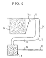
Bei der Ausführungsform nach Fig. 4 ist die Pumpenkammer PK mit der Dosierkammer DK über eine als kapillare Abreissdrossel ausgebildete Leitung 16 verbunden, die einen erweiterten Einlassabschnitt 16a aufweist. Die Pumpenkammer PK ist kapillar aktiv ausgebildet und enthält hierzu bevorzugt ein Vlies. Die Dosierkammer DK geht in diesem Fall ohne erkennbaren Übergang im Bereich 10 in einen Auslaufkanal RS über. Der Auslaufkanal RS führt in Richtung der Rotationsachse X-X des Rotors R bis zu einer Stelle, die näher an der Rotationsachse X-X liegt als die Flüssigkeitsoberfläche in der Pumpenkammer PK während der Rotation des Rotors R mit einer ersten erhöhten Drehzahl und führt dann radial von der Rotationsachse X-X fort. Im radial inneren Bereich führt der Auslaufkanal RS durch eine Kammer K, in der sich ein Saugvlies befindet.In the embodiment according to FIG. 4, the pump chamber PK is connected to the metering chamber DK via a
Bei der Ausführungsform nach Fig. 4 sind die Flüssigkeitsdosen, die durch den Auslaufkanal RS abgeführt werden, zwar grösser als in dem vorangehend beschriebenen Ausführungsbeispiel, bei dem der Auslaufkanal RS kapillar ausgebildet und daher mit Kap bezeichnet ist. Da wie weiter oben erwähnt, die Grösse eines Schlucks nicht nur durch das Volumen der Dosierkammer, sondern auch durch das während der ersten erhöhten Drehzahl gefüllte Teilvolumen des Auslaufkanals bestimmt wird, sind die Unterschiede im Volumen der einzelnen Schlucke um so grösser, je grösser der Querschnitt des Auslaufkanals ist. Für viele Anwendungszwecke kommt es aber auf eine besondere Gleichmässigkeit der Dosen nicht an, sondern nur darauf, dass die Gesamtdosis aus einer Mehrzahl von Dosen mit hinreichender Genauigkeit reproduzierbar die gleiche ist. Für einen solchen Anwendungszweck ist die Ausführungsform gemäss Fig. 4 besonders geeignet.In the embodiment according to FIG. 4, the liquid cans which are discharged through the outlet channel RS are larger than in the exemplary embodiment described above, in which the outlet channel RS is capillary and is therefore designated by cap. Since, as mentioned above, the size of a sip is determined not only by the volume of the metering chamber, but also by the partial volume of the outlet channel that was filled during the first increased speed, the larger the cross section, the greater the differences in the volume of the individual sips of the outlet channel. For many applications, it is not a question of a particular uniformity of the doses, but only that the total dose from a plurality of doses is reproducibly the same with sufficient accuracy. The embodiment according to FIG. 4 is particularly suitable for such an application.
Für die Funktion ist wesentlich, dass der Auslaufkanal RS aus der Dosierkammer DK so geführt ist, dass mindestens ein Teil von ihm radial näher an der Rotationsachse X-X des Rotors R liegt als die Flüssigkeitsoberfläche in der Pumpenkammer PK während einer Rotation mit einer ersten erhöhten Drehzahl. Bei einer nicht kapillarförmigen Gestaltung des Auslaufkanals RS fliesst die Flüssigkeit nur auf Grund der Schwerkraft aus der Dosierkammer, wenn die Drehzahl auf einen zweiten, niedrigeren Wert abgesenkt wird. Sie wird von dem Vlies in der Kammer K aufgesaugt. Alternativ oder zusätzlich kann auch hier der Auslaufkanal wie in Fig. 1 so gestaltet sein, dass sein Auslass radial auswärts der Dosierkammer liegt.It is essential for the function that the outlet channel RS is led out of the metering chamber DK in such a way that at least a part of it is located radially closer to the axis of rotation X-X of the rotor R than the liquid surface in the pump chamber PK during a rotation at a first increased speed. In the case of a non-capillary design of the outlet channel RS, the liquid flows from the metering chamber only due to the force of gravity when the speed is reduced to a second, lower value. It is sucked up by the fleece in the chamber K. Alternatively or additionally, the outlet channel can also be designed here, as in FIG. 1, so that its outlet is located radially outward of the metering chamber.
Claims (14)
Priority Applications (1)
| Application Number | Priority Date | Filing Date | Title |
|---|---|---|---|
| AT85108376T ATE43440T1 (en) | 1984-07-06 | 1985-07-05 | DEVICE FOR FLUSHING A SUBSTANCE IN A FIELD WITH A LIQUID DETERGENT IN SEVERAL FLUSHING CYCLES AND FOR TRANSFERRING THE DETERGENT OUT OF THE FIELD DURING THE LAST FLUSHING PROCESS INTO A CUEVETTE. |
Applications Claiming Priority (2)
| Application Number | Priority Date | Filing Date | Title |
|---|---|---|---|
| DE19843425009 DE3425009A1 (en) | 1984-07-06 | 1984-07-06 | DEVICE FOR RINSING A SUBSTANCE IN A FIELD WITH A LIQUID DETERGENT IN SEVERAL RINSE PROCEDURES AND FOR CONVERTING THE RINSING EQUIPMENT LEFT IN THE FIELD IN THE FIELD |
| DE3425009 | 1984-07-06 |
Publications (3)
| Publication Number | Publication Date |
|---|---|
| EP0167175A2 EP0167175A2 (en) | 1986-01-08 |
| EP0167175A3 EP0167175A3 (en) | 1987-09-30 |
| EP0167175B1 true EP0167175B1 (en) | 1989-05-24 |
Family
ID=6240050
Family Applications (1)
| Application Number | Title | Priority Date | Filing Date |
|---|---|---|---|
| EP85108376A Expired EP0167175B1 (en) | 1984-07-06 | 1985-07-05 | Device for washing a substance present in a field with a washing liquid in several washing steps and for transporting the washing fluid, emerging from said field, after the last washing step to a cuvette |
Country Status (8)
| Country | Link |
|---|---|
| US (1) | US4915911A (en) |
| EP (1) | EP0167175B1 (en) |
| JP (1) | JPS6126859A (en) |
| AT (1) | ATE43440T1 (en) |
| AU (1) | AU563672B2 (en) |
| DE (2) | DE3425009A1 (en) |
| DK (1) | DK298685A (en) |
| ES (1) | ES8701536A1 (en) |
Cited By (1)
| Publication number | Priority date | Publication date | Assignee | Title |
|---|---|---|---|---|
| EP0326135B1 (en) * | 1988-01-27 | 1993-03-31 | Roche Diagnostics GmbH | Carrier fleece for impregnated releasable reagents |
Families Citing this family (3)
| Publication number | Priority date | Publication date | Assignee | Title |
|---|---|---|---|---|
| US5173262A (en) * | 1987-07-17 | 1992-12-22 | Martin Marietta Energy Systems, Inc. | Rotor assembly and method for automatically processing liquids |
| US5242803A (en) * | 1987-07-17 | 1993-09-07 | Martin Marietta Energy Systems, Inc. | Rotor assembly and assay method |
| US4985631A (en) * | 1988-02-16 | 1991-01-15 | Wannlund Jon C | Luminescence exposure apparatus |
Family Cites Families (9)
| Publication number | Priority date | Publication date | Assignee | Title |
|---|---|---|---|---|
| US3801004A (en) * | 1972-09-22 | 1974-04-02 | Union Carbide Corp | Device for collecting the contents of cuvets in a rotating spectrophotometer analyzer |
| US3890101A (en) * | 1974-02-15 | 1975-06-17 | Us Energy | Collection ring for use in multiple-sample blood fractionation centrifugal rotors |
| US3899296A (en) * | 1974-07-17 | 1975-08-12 | Us Energy | Whole blood analysis rotor for a multistation dynamic photometer |
| US4284602A (en) * | 1979-12-10 | 1981-08-18 | Immutron, Inc. | Integrated fluid manipulator |
| CA1152353A (en) * | 1980-05-05 | 1983-08-23 | Georges Revillet | Multicuvette rotor for analyser |
| DE3044372A1 (en) * | 1980-11-25 | 1982-07-08 | Boehringer Mannheim Gmbh, 6800 Mannheim | ROTOR UNIT WITH INSERT ELEMENTS FOR A CENTRIFUGAL ANALYZER |
| DE3044385A1 (en) * | 1980-11-25 | 1982-06-24 | Boehringer Mannheim Gmbh, 6800 Mannheim | METHOD FOR CARRYING OUT ANALYTICAL PROVISIONS AND ROTOR INSERT ELEMENT SUITABLE FOR THIS |
| DE3134560A1 (en) * | 1981-09-01 | 1983-03-17 | Boehringer Mannheim Gmbh, 6800 Mannheim | DEVICE AND METHOD FOR CONTROLLING AND MIXING A LIQUID FLOW EXPOSED TO CENTRIFUGAL FORCE |
| IT1169162B (en) * | 1983-02-07 | 1987-05-27 | Azionaria Costruzioni Acma Spa | FEEDING OF SOAP TYPE PRODUCTS, FOR CONTINUOUS MOTOR RECEIVING MACHINE |
-
1984
- 1984-07-06 DE DE19843425009 patent/DE3425009A1/en not_active Withdrawn
-
1985
- 1985-06-28 AU AU44431/85A patent/AU563672B2/en not_active Expired - Fee Related
- 1985-07-01 DK DK298685A patent/DK298685A/en not_active Application Discontinuation
- 1985-07-04 JP JP14594585A patent/JPS6126859A/en active Granted
- 1985-07-05 AT AT85108376T patent/ATE43440T1/en not_active IP Right Cessation
- 1985-07-05 EP EP85108376A patent/EP0167175B1/en not_active Expired
- 1985-07-05 DE DE8585108376T patent/DE3570524D1/en not_active Expired
- 1985-07-05 ES ES544889A patent/ES8701536A1/en not_active Expired
-
1987
- 1987-09-21 US US07/098,780 patent/US4915911A/en not_active Expired - Fee Related
Cited By (1)
| Publication number | Priority date | Publication date | Assignee | Title |
|---|---|---|---|---|
| EP0326135B1 (en) * | 1988-01-27 | 1993-03-31 | Roche Diagnostics GmbH | Carrier fleece for impregnated releasable reagents |
Also Published As
| Publication number | Publication date |
|---|---|
| DE3570524D1 (en) | 1989-06-29 |
| DK298685D0 (en) | 1985-07-01 |
| AU563672B2 (en) | 1987-07-16 |
| ES8701536A1 (en) | 1986-12-16 |
| EP0167175A3 (en) | 1987-09-30 |
| EP0167175A2 (en) | 1986-01-08 |
| US4915911A (en) | 1990-04-10 |
| ES544889A0 (en) | 1986-12-16 |
| DK298685A (en) | 1986-01-07 |
| JPS6126859A (en) | 1986-02-06 |
| DE3425009A1 (en) | 1986-02-06 |
| JPH0481743B2 (en) | 1992-12-24 |
| AU4443185A (en) | 1986-01-09 |
| ATE43440T1 (en) | 1989-06-15 |
Similar Documents
| Publication | Publication Date | Title |
|---|---|---|
| EP0039825B1 (en) | Cuvette rotor for analyzer and method of operation of said cuvette rotor | |
| EP0073512B1 (en) | Apparatus and method for controlling and mixing a liquid subjected to a centrifugal force | |
| EP2072131B1 (en) | Microfluid element for mixing a fluid into a reagent | |
| DE60035611T2 (en) | MICRO FLUID ANALYSIS DEVICE | |
| DE69730893T2 (en) | pretreatment device | |
| DE60132198T2 (en) | PLATE DISTRIBUTION DEVICE FOR BLOOD COMPONENTS | |
| DE3134611A1 (en) | METHOD FOR CARRYING OUT ANALYTICAL PROVISIONS AND MEANS SUITABLE FOR THIS | |
| EP2506959B1 (en) | Microfluidic element for analysing a fluid sample | |
| EP2632591B1 (en) | Microfluidic element for analysis of a sample liquid | |
| DE69737619T2 (en) | Automatic analyzer washing device | |
| DE2336619C2 (en) | Photometric analyzer | |
| EP3592463B1 (en) | Method for centrifugo-pneumatic switching of liquid | |
| DE2051707A1 (en) | Precision pipette | |
| EP2428272B1 (en) | Method for hydrophobic coating of pipette tips | |
| EP1474235A1 (en) | Sample preparation device and test device set based thereon | |
| DE2523513A1 (en) | REACTION VESSEL FOR CHEMICAL ANALYSIS | |
| DE2117423B2 (en) | SAMPLE CARRIAGE AND TRANSPORT DEVICE | |
| EP0167175B1 (en) | Device for washing a substance present in a field with a washing liquid in several washing steps and for transporting the washing fluid, emerging from said field, after the last washing step to a cuvette | |
| EP3263215B1 (en) | Device with a flow cell with reagent storage | |
| DE3310205C2 (en) | Device for receiving, transporting and obtaining cell material and for transferring the cell material obtained onto microscope slides | |
| DE1815502C3 (en) | Method and device for mixing and transferring a sample liquid | |
| DE102011079698B4 (en) | Microfluidic device having a chamber for storing a liquid | |
| DE102021208891B3 (en) | Fluid vacuum switching | |
| EP1833598B1 (en) | Method and device for dosing and mixing small amounts of liquid | |
| DE3703189C2 (en) |
Legal Events
| Date | Code | Title | Description |
|---|---|---|---|
| PUAI | Public reference made under article 153(3) epc to a published international application that has entered the european phase |
Free format text: ORIGINAL CODE: 0009012 |
|
| 17P | Request for examination filed |
Effective date: 19850705 |
|
| AK | Designated contracting states |
Designated state(s): AT BE CH DE FR GB IT LI LU NL SE |
|
| PUAL | Search report despatched |
Free format text: ORIGINAL CODE: 0009013 |
|
| AK | Designated contracting states |
Kind code of ref document: A3 Designated state(s): AT BE CH DE FR GB IT LI LU NL SE |
|
| 17Q | First examination report despatched |
Effective date: 19880222 |
|
| GRAA | (expected) grant |
Free format text: ORIGINAL CODE: 0009210 |
|
| AK | Designated contracting states |
Kind code of ref document: B1 Designated state(s): AT BE CH DE FR GB IT LI LU NL SE |
|
| PG25 | Lapsed in a contracting state [announced via postgrant information from national office to epo] |
Ref country code: SE Effective date: 19890524 Ref country code: NL Effective date: 19890524 Ref country code: IT Free format text: LAPSE BECAUSE OF FAILURE TO SUBMIT A TRANSLATION OF THE DESCRIPTION OR TO PAY THE FEE WITHIN THE PRESCRIBED TIME-LIMIT;WARNING: LAPSES OF ITALIAN PATENTS WITH EFFECTIVE DATE BEFORE 2007 MAY HAVE OCCURRED AT ANY TIME BEFORE 2007. THE CORRECT EFFECTIVE DATE MAY BE DIFFERENT FROM THE ONE RECORDED. Effective date: 19890524 Ref country code: BE Effective date: 19890524 |
|
| REF | Corresponds to: |
Ref document number: 43440 Country of ref document: AT Date of ref document: 19890615 Kind code of ref document: T |
|
| GBT | Gb: translation of ep patent filed (gb section 77(6)(a)/1977) | ||
| REF | Corresponds to: |
Ref document number: 3570524 Country of ref document: DE Date of ref document: 19890629 |
|
| PG25 | Lapsed in a contracting state [announced via postgrant information from national office to epo] |
Ref country code: AT Effective date: 19890705 |
|
| PG25 | Lapsed in a contracting state [announced via postgrant information from national office to epo] |
Ref country code: LU Free format text: LAPSE BECAUSE OF NON-PAYMENT OF DUE FEES Effective date: 19890731 Ref country code: LI Effective date: 19890731 Ref country code: CH Effective date: 19890731 |
|
| ET | Fr: translation filed | ||
| NLV1 | Nl: lapsed or annulled due to failure to fulfill the requirements of art. 29p and 29m of the patents act | ||
| PLBE | No opposition filed within time limit |
Free format text: ORIGINAL CODE: 0009261 |
|
| STAA | Information on the status of an ep patent application or granted ep patent |
Free format text: STATUS: NO OPPOSITION FILED WITHIN TIME LIMIT |
|
| REG | Reference to a national code |
Ref country code: CH Ref legal event code: PL |
|
| 26N | No opposition filed | ||
| PGFP | Annual fee paid to national office [announced via postgrant information from national office to epo] |
Ref country code: GB Payment date: 19910624 Year of fee payment: 7 |
|
| PG25 | Lapsed in a contracting state [announced via postgrant information from national office to epo] |
Ref country code: GB Effective date: 19920705 |
|
| GBPC | Gb: european patent ceased through non-payment of renewal fee |
Effective date: 19920705 |
|
| PGFP | Annual fee paid to national office [announced via postgrant information from national office to epo] |
Ref country code: DE Payment date: 20010625 Year of fee payment: 17 |
|
| PGFP | Annual fee paid to national office [announced via postgrant information from national office to epo] |
Ref country code: FR Payment date: 20010712 Year of fee payment: 17 |
|
| PG25 | Lapsed in a contracting state [announced via postgrant information from national office to epo] |
Ref country code: DE Free format text: LAPSE BECAUSE OF NON-PAYMENT OF DUE FEES Effective date: 20030201 |
|
| PG25 | Lapsed in a contracting state [announced via postgrant information from national office to epo] |
Ref country code: FR Free format text: LAPSE BECAUSE OF NON-PAYMENT OF DUE FEES Effective date: 20030331 |
|
| REG | Reference to a national code |
Ref country code: FR Ref legal event code: ST |