EP0167080B1 - Commande à calculatrice pour un robot industriel à plusieurs axes - Google Patents
Commande à calculatrice pour un robot industriel à plusieurs axes Download PDFInfo
- Publication number
- EP0167080B1 EP0167080B1 EP85107782A EP85107782A EP0167080B1 EP 0167080 B1 EP0167080 B1 EP 0167080B1 EP 85107782 A EP85107782 A EP 85107782A EP 85107782 A EP85107782 A EP 85107782A EP 0167080 B1 EP0167080 B1 EP 0167080B1
- Authority
- EP
- European Patent Office
- Prior art keywords
- speed
- path
- axis
- robot
- values
- Prior art date
- Legal status (The legal status is an assumption and is not a legal conclusion. Google has not performed a legal analysis and makes no representation as to the accuracy of the status listed.)
- Expired
Links
Images


Classifications
-
- G—PHYSICS
- G05—CONTROLLING; REGULATING
- G05B—CONTROL OR REGULATING SYSTEMS IN GENERAL; FUNCTIONAL ELEMENTS OF SUCH SYSTEMS; MONITORING OR TESTING ARRANGEMENTS FOR SUCH SYSTEMS OR ELEMENTS
- G05B19/00—Programme-control systems
- G05B19/02—Programme-control systems electric
- G05B19/18—Numerical control [NC], i.e. automatically operating machines, in particular machine tools, e.g. in a manufacturing environment, so as to execute positioning, movement or co-ordinated operations by means of programme data in numerical form
- G05B19/416—Numerical control [NC], i.e. automatically operating machines, in particular machine tools, e.g. in a manufacturing environment, so as to execute positioning, movement or co-ordinated operations by means of programme data in numerical form characterised by control of velocity, acceleration or deceleration
Definitions
- the invention relates to a method for controlling a multi-axis industrial robot, in which the movement of the robot tip, which is predetermined in terms of the spatial reference to the base point of the robot, is transformed into corresponding target values for the rotary movements of rotary or travel paths of linear drives of the individual axes, in which case , if at least one speed setpoint of an axis exceeds its assigned limit value, the path speed of the predetermined movement is reduced until none of the speed setpoints exceeds its assigned limit value.
- the object of the present invention is to design a controller of the type mentioned in the introduction in such a way that an extremely stable control method is achieved.
- This object is achieved in that the path speed of the robot tip in predetermined position ranges of individual axes, i. H. Angular ranges for rotary or distance ranges for linear drives, is additionally reduced and that the range limits of the position areas are made dependent on the respective path speed and the amount of path acceleration of the robot tip such that the higher the path speed and the lower the amount of acceleration of the Path speed is, the more the area width is enlarged.
- the articulated industrial robot shown schematically in FIG. 1 has six joints 1 to 6, by means of which rotations in six axes a1 to a6 are possible.
- the three-phase motors 7 used to drive the individual joints 1 to 6 are integrated into the joints 1 to 6 together with the associated reduction gears and the displacement sensors 8 flanged onto them.
- the schematically shown tool 100 is then arranged on the joint 6.
- the system 9 used to feed the motors 7, which is arranged in a stationary manner in a control cabinet - as indicated by the broken line 16 - consists of a converter 11 connected to a three-phase network 10, a DC voltage intermediate circuit 12 with a capacitor bank 13 and individual converters 14 for the supply of the motors 7.
- Each converter 14 is assigned a control part 15 which, as arranged by the arrow 18, receives its control commands from a computer control 17.
- a control is described, for example, in the Siemens magazine 1981, pages 285 to 289.
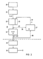
- the paths to be traversed by the robot tip 19, e.g. B. the straight line L, which is to be traversed at a given speed V, is given in relation to a stationary coordinate system xyz.
- These predetermined Cartesian coordinate values are converted by the control system into corresponding rotary movements of the individual axes a1 to a6. Transformations of this type are described in more detail, for example, in the US patents mentioned at the beginning. Should z. B. the tip 19 run on the mentioned path L and at the same time the orientation of the tool 100 held there should remain constant in space, it does not fail that under certain circumstances all axes of the robot can be controlled while traversing a path.
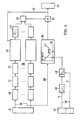
- the basic structure of the control is shown in FIG. 2, for the sake of simplicity the units which may have been combined in a computer are shown in individual function blocks.
- the program coming from a user program memory 20 is decoded with the predetermined movement in a decoding module 21 and in an interpolator 22, the intermediate points lying between predetermined points are calculated, the speed of the output of the intermediate points determining the movement speed V.
- the adjustability of this speed output is indicated by the web speed guide part 23.
- the values output by the interpolator 22 are in the Cartesian co-ordinate system x, y, z, which is fixed in space.
- the values are therefore transformed in a transformation block 24 from Cartesian coordinates xyz into corresponding target values (target angle) for the axes a1 to a6.
- These setpoints for the axes ⁇ 1 to a6, which are also output at a predetermined speed, are finely interpolated again in fine interpolators 25 and then sent to a position controller 26 which outputs the individual speed setpoints to the control parts 15 of the motors 7.
- a control of this type is known in principle from the Siemens magazine mentioned at the beginning.
- control unit 27 for optimally changing the path speed, and this applies above all to the cases in which the transformation would result in impermissible speeds in individual axes.
- the desired speeds to be expected from the present changes in the angles in the individual axes a1 to a6 are extrapolated in the module 27 and it is checked whether the permissible speed (angular speed) is exceeded in one axis. If this is the case, then - as indicated by line 37 - the web speed guiding part 23 (override) is intervened in a regulating manner and the web speed V is reduced until the limit value is again undershot.
- a certain rotation angle range is therefore monitored in axis a5 and the speed is also additionally reduced in this range.
- the point of use can be changed depending on the specified target speed v on the path or the associated acceleration.
- Figure 3 shows some further details.
- the setpoints coming from the individual axes ⁇ 1 to a6 are checked in the limit value monitoring element 28 to determine whether one of these setpoints changes too quickly, i. H. a predetermined speed is exceeded. If this is the case, the web speed is reduced by a certain amount, as indicated by the module 30.
- the axis is also monitored with the angle of rotation a5, as indicated by the module 29.
- the web speed is then also reduced according to a predetermined function. This then results in a further reduction factor, which is indicated by the module 31.
- These two values, which are present in module 30 and 31, are multiplied together in a multiplier 32 and serve as an override value in a memory 35. This is the value with which the predetermined path speed V is corrected, i. H. is normally reduced.
- Figure 4 shows further details of the control.
- angle values of the axes are initially used a1 to ⁇ 6 on lines 39 to 'to the angle difference to form successive angle values, as indicated by block 40th Since this difference is formed in a predetermined time grid, the resulting values are also a measure of the speed of the axis in question.
- a number of the speed values obtained in this way are then used to extrapolate one step in advance, as indicated by the extrapolation module 41.
- the absolute value of this value is then formed in a module 42 and continuously fed to an integral controller 43.
- this integral controller 43 is according to the relationship where tlaG maximum permissible speed value and ⁇ k + 1 are the extrapolated speed of the relevant axis, a value is formed which indicates to what extent the speed in the relevant axis would move away from the predetermined limit value ⁇ G.
- This control value thus obtained is passed via a limiting module 44 and fed to a selection circuit 45.
- Such processing of the transformed angles of rotation is also carried out in the other axes a2 to ⁇ 6.
- the selection circuit 45 now ensures that the axis in which the limit value is the most is exceeded, comes into play in such a way that the value resulting at the controller output is used via the multiplier 32 as an override signal for guiding the path speed V in module 23.
- This regulation is effective as long as the specified limit value is exceeded in one of the axes.
- the control behavior I of the controller 43 is still changed depending on the resulting web speed V.
- the angle of rotation in axis a5 is evaluated via line 391 in such a way that between values of the angle of z. B. ⁇ 20 ° around the zero point, the path speed V is reduced by a certain factor. This factor is multiplicatively linked in the link 32 with the reduction factor coming from the integral controller 43.
- the values for acceleration b and speed v coming from the interpolator 22 are also used via controllers 48, 49 to shift the range limits within which the speed is reduced, and this is done in such a way that with increasing speed and decreasing Acceleration this area is widened and vice versa.
- FIG. 5 shows, for example, a predefined path speed curve V along the straight line L as a function of time t, without the control described above.
- this can lead, for example, to the fact that the speed ⁇ 1 in the axis a1 would far exceed the maximum permissible value ⁇ G , whereas - as can be seen in FIG. 7 - the resulting speed change in the axis a2 is below the maximum permissible limit value ⁇ G would remain in this axis.
- Figures 8 to 10 show the conditions when using the speed control described above. 8, the same path speed curve with the same time profile as in FIG. 5 is used as a basis. As can be seen and as can be seen from the dotted curve in FIG. 9, this would lead to the permissible maximum value being exceeded in axis a1. If the exceeding of the maximum permissible limit value as a result of the transformation is determined by extrapolation, the web speed V is reduced at time t 1 . This results in the solid line for the speed setpoint in axis a1 according to FIG. 9. This then also leads - in deviation from the original course indicated by dotted lines - to the continuous speed curve ⁇ 2 in axis a2 (FIG. 10), etc.
- control ensures that the web speed V is reduced only as long and to the extent that the speed is not inadmissibly exceeded in any of the axes a1 to a6.
- FIG. 11 shows the extrapolation method, namely the time course of the speed setpoints is plotted on one axis. It is assumed that the setpoint is present at time k. Then, with the aid of the target values at times k-1 and k-2, the expected value at time k + 1 is extrapolated in advance according to a Taylor development. This previously extrapolated value is then compared with the assigned limit value and the procedure mentioned in connection with the figures described above is initiated.
- FIGS. 12 and 13 show the control behavior of the integral controller according to FIG. 4.
- the extrapolation carried out at time t1 results in a value to be expected at time t2 that exceeds the predetermined limit value ⁇ G. Therefore, at time t1, the web speed is reduced from 100% by a factor r1, in accordance with the control deviation of the controller.
- the calculation at time t2 shows that at time t3 the limit value can be exceeded even more.
- the web speed V is reduced even more at time t2.
- the prediction shows that the next value would be below the limit value ⁇ G. Accordingly, the speed V is correspondingly increased again at the time t5, etc., until the original speed is then reached again at the time t7.
- the possible speed reduction can go down to 1% of the maximum possible speed.
Landscapes
- Engineering & Computer Science (AREA)
- Human Computer Interaction (AREA)
- Manufacturing & Machinery (AREA)
- Physics & Mathematics (AREA)
- General Physics & Mathematics (AREA)
- Automation & Control Theory (AREA)
- Numerical Control (AREA)
- Manipulator (AREA)
Claims (4)
Applications Claiming Priority (2)
| Application Number | Priority Date | Filing Date | Title |
|---|---|---|---|
| DE3424762 | 1984-07-05 | ||
| DE3424762 | 1984-07-05 |
Publications (2)
| Publication Number | Publication Date |
|---|---|
| EP0167080A1 EP0167080A1 (fr) | 1986-01-08 |
| EP0167080B1 true EP0167080B1 (fr) | 1989-09-20 |
Family
ID=6239916
Family Applications (1)
| Application Number | Title | Priority Date | Filing Date |
|---|---|---|---|
| EP85107782A Expired EP0167080B1 (fr) | 1984-07-05 | 1985-06-24 | Commande à calculatrice pour un robot industriel à plusieurs axes |
Country Status (4)
| Country | Link |
|---|---|
| US (1) | US4734866A (fr) |
| EP (1) | EP0167080B1 (fr) |
| JP (1) | JPS6126107A (fr) |
| DE (1) | DE3573178D1 (fr) |
Cited By (1)
| Publication number | Priority date | Publication date | Assignee | Title |
|---|---|---|---|---|
| WO2024064988A1 (fr) | 2022-09-30 | 2024-04-04 | Wittmann Technology Gmbh | Procédé et dispositif pour commander le mouvement d'un élément de manipulation |
Families Citing this family (21)
| Publication number | Priority date | Publication date | Assignee | Title |
|---|---|---|---|---|
| JPS62172581U (fr) * | 1986-04-22 | 1987-11-02 | ||
| JPS6375904A (ja) * | 1986-09-19 | 1988-04-06 | Hitachi Ltd | 多関節構造機械の軌跡制御装置 |
| JPH0754447B2 (ja) * | 1986-09-25 | 1995-06-07 | 株式会社神戸製鋼所 | 産業用ロボツトの速度制御方法 |
| JP2617931B2 (ja) * | 1987-04-07 | 1997-06-11 | 三菱電機株式会社 | ワーク加工装置の加工速度設定方法 |
| US4956789A (en) * | 1987-05-13 | 1990-09-11 | Hitachi, Ltd. | Method and apparatus for driving a servo system while suppressing residual vibration generated during position control |
| DE3724428A1 (de) * | 1987-07-23 | 1989-02-02 | Christian Loeffler | Verfahren zur direkten speicherung eines bewegungsablaufes in echtzeit und exakter wiedergabe dieser bewegung sowohl in zeit als auch ort |
| JPS6481011A (en) * | 1987-09-22 | 1989-03-27 | Fanuc Ltd | Speed control system for polar coordinate system |
| JP2566665B2 (ja) * | 1990-06-27 | 1996-12-25 | 川崎重工業株式会社 | 慣性系におけるロボットの制御装置 |
| DE4123323C2 (de) * | 1991-07-13 | 1994-02-10 | Andreas Ehlerding | Werkzeugträger |
| US5373221A (en) * | 1993-07-30 | 1994-12-13 | Fanuc Robotics North America, Inc. | Method and system for estimating robot tool center point speed |
| US5602968A (en) * | 1994-05-02 | 1997-02-11 | The United States Of America As Represented By The Administrator Of The National Aeronautics And Space Administration | Task space angular velocity blending for real-time trajectory generation |
| US5740327A (en) * | 1994-12-27 | 1998-04-14 | Nec Corporation | Method of and apparatus for robot tip trajectory control |
| DE19841716A1 (de) * | 1998-09-11 | 2000-03-16 | Siemens Ag | Steuerungsverfahren und numerische Steuerung zur Bewegungsführung von industriellen Bearbeitungsmaschinen |
| US6493608B1 (en) * | 1999-04-07 | 2002-12-10 | Intuitive Surgical, Inc. | Aspects of a control system of a minimally invasive surgical apparatus |
| SE0100974D0 (sv) * | 2001-03-20 | 2001-03-20 | Abb Ab | Termisk optimeringsmetod |
| JP2005081445A (ja) * | 2003-09-04 | 2005-03-31 | Fanuc Ltd | ロボットの干渉領域確認装置 |
| EP1538501B2 (fr) * | 2003-11-19 | 2010-10-06 | Siemens Aktiengesellschaft | Procédé pour surveiller une installation technique |
| US7904182B2 (en) * | 2005-06-08 | 2011-03-08 | Brooks Automation, Inc. | Scalable motion control system |
| JP4291385B2 (ja) * | 2007-09-27 | 2009-07-08 | ファナック株式会社 | ロボット手先部の速度に基づいてロボットを停止させるロボット制御装置 |
| FR2929873B1 (fr) | 2008-04-09 | 2010-09-03 | Aldebaran Robotics | Architecture de controle-commande d'un robot mobile utilisant des membres articules |
| US9193573B1 (en) * | 2012-05-11 | 2015-11-24 | The Boeing Company | Process for measuring and controlling extension of scissor linkage systems |
Family Cites Families (8)
| Publication number | Priority date | Publication date | Assignee | Title |
|---|---|---|---|---|
| US3479574A (en) * | 1966-11-18 | 1969-11-18 | Bunker Ramo | Feed rate computer and squaring circuit for a pulse responsive multiaxes servo system |
| US3909600A (en) * | 1972-06-26 | 1975-09-30 | Cincinnati Milacron Inc | Method and apparatus for controlling an automation along a predetermined path |
| US3920972A (en) * | 1974-07-16 | 1975-11-18 | Cincinnati Milacron Inc | Method and apparatus for programming a computer operated robot arm |
| US4338672A (en) * | 1978-04-20 | 1982-07-06 | Unimation, Inc. | Off-line teach assist apparatus and on-line control apparatus |
| JPS5633704A (en) * | 1979-08-28 | 1981-04-04 | Mitsubishi Electric Corp | Velocity clamping device for numerical value controller |
| JPS57139810A (en) * | 1981-02-20 | 1982-08-30 | Shin Meiwa Ind Co Ltd | Controlling method of industrial robot and its device |
| JPS584377A (ja) * | 1981-03-18 | 1983-01-11 | 株式会社安川電機 | 関節形産業用ロボツトの制御装置 |
| JPS58143981A (ja) * | 1982-02-19 | 1983-08-26 | 株式会社日立製作所 | 産業用ロボツトの制御方法 |
-
1985
- 1985-06-10 US US06/742,805 patent/US4734866A/en not_active Expired - Fee Related
- 1985-06-24 EP EP85107782A patent/EP0167080B1/fr not_active Expired
- 1985-06-24 DE DE8585107782T patent/DE3573178D1/de not_active Expired
- 1985-07-03 JP JP14642885A patent/JPS6126107A/ja active Pending
Cited By (1)
| Publication number | Priority date | Publication date | Assignee | Title |
|---|---|---|---|---|
| WO2024064988A1 (fr) | 2022-09-30 | 2024-04-04 | Wittmann Technology Gmbh | Procédé et dispositif pour commander le mouvement d'un élément de manipulation |
Also Published As
| Publication number | Publication date |
|---|---|
| US4734866A (en) | 1988-03-29 |
| JPS6126107A (ja) | 1986-02-05 |
| EP0167080A1 (fr) | 1986-01-08 |
| DE3573178D1 (en) | 1989-10-26 |
Similar Documents
| Publication | Publication Date | Title |
|---|---|---|
| EP0167080B1 (fr) | Commande à calculatrice pour un robot industriel à plusieurs axes | |
| DE3344633C2 (fr) | ||
| EP0113010B1 (fr) | Système pour la commande d'un robot | |
| DE2712169C2 (de) | Verfahren zur Ausführung einer komplexen Bewegung durch einen Industrieroboter | |
| DE3317263A1 (de) | Manipulator mit adaptiver geschwindigkeitsgesteuerter bahnbewegung | |
| EP1591209A2 (fr) | Procédé de commander une machine, en particulier un robot industriel | |
| DE2735632A1 (de) | Verfahren und anordnung zum steuern eines industrie-roboters | |
| EP1604789A2 (fr) | Méthode et dispositif pour améliorer la précision du positionnement d'un manipulateur | |
| DE102014103370B4 (de) | Verfahren und Vorrichtung zur zeitdiskreten Steuerung eines Manipulators | |
| DE19841716A1 (de) | Steuerungsverfahren und numerische Steuerung zur Bewegungsführung von industriellen Bearbeitungsmaschinen | |
| EP0530401B1 (fr) | Méthode de déclenchement d'opérations en fonction de la position pendant l'usinage par un robot ou une machine-outil | |
| EP0165436B1 (fr) | Méthode pour réduire la mémoire occupée par le programme pour les mouvements d'un robot | |
| DE3314466C2 (fr) | ||
| DE4019218A1 (de) | Verfahren und system zur regelung des mittleren stroms durch eine last sowie elektrische fernsteuervorrichtung nach art eines manipulators, bei der das verfahren bzw. das system angewendet werden | |
| DE3504889A1 (de) | Vorrichtung und verfahren zum regeln von synchronantriebseinrichtungen | |
| EP2135143B1 (fr) | Procédé et dispositif pour guider le déplacement d'un organe mobile d'une machine à commande numérique | |
| EP0417337B1 (fr) | Procédé de fonctionnement d'une machine-outil à commande numérique ou d'un robot | |
| DE102005032336B4 (de) | Verfahren zur Beeinflussung einer Steuerung oder zur Steuerung einer Bewegungseinrichtung und Steuerung oder Steuerungskomponente einer Bewegungseinrichtung | |
| DE4213927A1 (de) | Verfahren zur steuerung einer werkzeugmaschine, insbesondere eine fraesmaschine | |
| EP1229411A2 (fr) | Procédé de commande et structure de régulation pour la commande du déplacement, la commande de l'action positive et l'interpolation fine d'objects dans un cycle de régulation de la vitesse angulaire qui est plus rapide que le cycle de régulation de la position | |
| WO2001033304A2 (fr) | Systeme de regulation pour organes de commande electriques et procede de regulation de trajectoire | |
| DE3938083C2 (fr) | ||
| DE1549634B1 (de) | Anordnung zur numerischen bahnsteuerung insbesondere bei einer werkzeugmaschine | |
| EP0844542B1 (fr) | Méthode et structure de commande numérique pour contrÔler le mouvement d'objets avec cadencement du contrÔle de vitesse supérieur à celui du contrÔle de position | |
| EP3847507B1 (fr) | Commande à régulation de position à compensation d'erreurs de position inhérentes à l'élasticité |
Legal Events
| Date | Code | Title | Description |
|---|---|---|---|
| PUAI | Public reference made under article 153(3) epc to a published international application that has entered the european phase |
Free format text: ORIGINAL CODE: 0009012 |
|
| AK | Designated contracting states |
Designated state(s): DE IT SE |
|
| 17P | Request for examination filed |
Effective date: 19860128 |
|
| 17Q | First examination report despatched |
Effective date: 19870720 |
|
| GRAA | (expected) grant |
Free format text: ORIGINAL CODE: 0009210 |
|
| AK | Designated contracting states |
Kind code of ref document: B1 Designated state(s): DE IT SE |
|
| REF | Corresponds to: |
Ref document number: 3573178 Country of ref document: DE Date of ref document: 19891026 |
|
| ITF | It: translation for a ep patent filed |
Owner name: STUDIO JAUMANN |
|
| PLBE | No opposition filed within time limit |
Free format text: ORIGINAL CODE: 0009261 |
|
| STAA | Information on the status of an ep patent application or granted ep patent |
Free format text: STATUS: NO OPPOSITION FILED WITHIN TIME LIMIT |
|
| 26N | No opposition filed | ||
| ITTA | It: last paid annual fee | ||
| PGFP | Annual fee paid to national office [announced via postgrant information from national office to epo] |
Ref country code: SE Payment date: 19940613 Year of fee payment: 10 |
|
| PGFP | Annual fee paid to national office [announced via postgrant information from national office to epo] |
Ref country code: DE Payment date: 19940819 Year of fee payment: 10 |
|
| EAL | Se: european patent in force in sweden |
Ref document number: 85107782.6 |
|
| PG25 | Lapsed in a contracting state [announced via postgrant information from national office to epo] |
Ref country code: SE Effective date: 19950625 |
|
| PG25 | Lapsed in a contracting state [announced via postgrant information from national office to epo] |
Ref country code: DE Effective date: 19960301 |
|
| EUG | Se: european patent has lapsed |
Ref document number: 85107782.6 |