EP0166286B1 - Joint d'étanchéité pour vanne à obturateur rotatif et son procédé de fabrication - Google Patents
Joint d'étanchéité pour vanne à obturateur rotatif et son procédé de fabrication Download PDFInfo
- Publication number
- EP0166286B1 EP0166286B1 EP85107099A EP85107099A EP0166286B1 EP 0166286 B1 EP0166286 B1 EP 0166286B1 EP 85107099 A EP85107099 A EP 85107099A EP 85107099 A EP85107099 A EP 85107099A EP 0166286 B1 EP0166286 B1 EP 0166286B1
- Authority
- EP
- European Patent Office
- Prior art keywords
- seal
- ring
- resilient ring
- axial
- solid part
- Prior art date
- Legal status (The legal status is an assumption and is not a legal conclusion. Google has not performed a legal analysis and makes no representation as to the accuracy of the status listed.)
- Expired
Links
Images


Classifications
-
- F—MECHANICAL ENGINEERING; LIGHTING; HEATING; WEAPONS; BLASTING
- F16—ENGINEERING ELEMENTS AND UNITS; GENERAL MEASURES FOR PRODUCING AND MAINTAINING EFFECTIVE FUNCTIONING OF MACHINES OR INSTALLATIONS; THERMAL INSULATION IN GENERAL
- F16K—VALVES; TAPS; COCKS; ACTUATING-FLOATS; DEVICES FOR VENTING OR AERATING
- F16K1/00—Lift valves or globe valves, i.e. cut-off apparatus with closure members having at least a component of their opening and closing motion perpendicular to the closing faces
- F16K1/16—Lift valves or globe valves, i.e. cut-off apparatus with closure members having at least a component of their opening and closing motion perpendicular to the closing faces with pivoted closure-members
- F16K1/18—Lift valves or globe valves, i.e. cut-off apparatus with closure members having at least a component of their opening and closing motion perpendicular to the closing faces with pivoted closure-members with pivoted discs or flaps
- F16K1/22—Lift valves or globe valves, i.e. cut-off apparatus with closure members having at least a component of their opening and closing motion perpendicular to the closing faces with pivoted closure-members with pivoted discs or flaps with axis of rotation crossing the valve member, e.g. butterfly valves
- F16K1/226—Shaping or arrangements of the sealing
- F16K1/2263—Shaping or arrangements of the sealing the sealing being arranged on the valve seat
-
- F—MECHANICAL ENGINEERING; LIGHTING; HEATING; WEAPONS; BLASTING
- F16—ENGINEERING ELEMENTS AND UNITS; GENERAL MEASURES FOR PRODUCING AND MAINTAINING EFFECTIVE FUNCTIONING OF MACHINES OR INSTALLATIONS; THERMAL INSULATION IN GENERAL
- F16K—VALVES; TAPS; COCKS; ACTUATING-FLOATS; DEVICES FOR VENTING OR AERATING
- F16K1/00—Lift valves or globe valves, i.e. cut-off apparatus with closure members having at least a component of their opening and closing motion perpendicular to the closing faces
- F16K1/16—Lift valves or globe valves, i.e. cut-off apparatus with closure members having at least a component of their opening and closing motion perpendicular to the closing faces with pivoted closure-members
- F16K1/18—Lift valves or globe valves, i.e. cut-off apparatus with closure members having at least a component of their opening and closing motion perpendicular to the closing faces with pivoted closure-members with pivoted discs or flaps
- F16K1/22—Lift valves or globe valves, i.e. cut-off apparatus with closure members having at least a component of their opening and closing motion perpendicular to the closing faces with pivoted closure-members with pivoted discs or flaps with axis of rotation crossing the valve member, e.g. butterfly valves
- F16K1/226—Shaping or arrangements of the sealing
- F16K1/228—Movable sealing bodies
- F16K1/2285—Movable sealing bodies the movement being caused by the flowing medium
Definitions
- the present invention relates to a seal for a valve and its manufacturing process, and more particularly to a seal resistant to high temperatures and to high pressures, intended for a valve comprising a rotary shutter.
- an elastic seal for example made of elastomeric material is used to seal between a valve body and its pivoting shutter. Seals of this type correctly perform this function when the temperature of the fluid passing through the valve does not exceed 120 ° C, when the pressure is less than about 20 bar, and when the fluid does not degrade the material constituting the seal.
- fluorinated hydrocarbon polymers the best known of which is polytetrafluoroethylene (PTFE). These materials are inert to many fluids and can also withstand pressures and temperatures much higher than those that can be supported by elastomeric materials.
- PTFE polytetrafluoroethylene
- these fluorinated hydrocarbon polymers have the following drawbacks when they have been subjected to deformation, they only return to their initial shape very slowly and when they are subjected to prolonged deformation, either in compression or in traction, they deform almost permanently, a phenomenon well known under the name of creep.
- US Pat. No. 4,266,752 discloses a seal intended to be mounted in a butterfly valve.
- This joint is made up of a Teflon ring (Teflon is a trademark registered by Du Pont de Nemours) comprising a massive part and a coaxial annular flange.
- Teflon is a trademark registered by Du Pont de Nemours
- a ring made of a material having a high Poisson's ratio and a low Young's modulus.
- the Applicant has posed the problem of providing a seal made of fluorinated hydrocarbon polymer provided with an elastic ring which prevents it from creeping cold and gives it good mechanical qualities when used with fluids. hot.
- the invention relates to a seal as defined in the preamble of claim 1 and characterized in the second part of the claim.
- the invention also relates to a method of manufacturing a seal according to the invention, this method is characterized in claims 7 and 8.
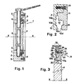
- the butterfly valve 1 shown in Figure 1 comprises a body 2 pierced with an axial channel 3 of axis XX which can be closed by a shutter 4 fixed on a rotary shaft 5 journalled in two diametrically opposite bores 6 and 7 of the body 2 which ends in two planar annular faces 8 parallel to each other allowing the valve to be fixed between two opposite flanges, not shown, of two adjacent sections of a pipe.
- the fluid can circulate in the axial channel 3 in one direction or the other.
- An elastic seal 9 according to the invention is arranged in a groove 10 shown in FIG. 2, machined partly in the body 2 and partly in an annular retaining ring 11 fixed to the body 2 by head screws embedded 12.
- the groove 10 comprises a wide part 10a opening into the axial channel 3 and a narrower blind part 10b directed radially towards the outside of the valve.
- the wide part 10a of the groove 10 is provided with two shoulders 13 and 14 projecting at the outlet on the channel 3.
- the shoulder 14 is formed by the connection of a radial surface 10d adjacent to the channel 3 with one radial lateral faces of the wide part 10a of the groove 10 while the shoulder 13 is formed by the connection of a frustoconical surface 10c adjacent to the channel 3, of axis of revolution XX, with the other radial lateral face of the wide part 10a of the groove 10.
- the elastic seal 9, shown in FIG. 3, consists of a solid part 15, in the form of a circular ring, the outer edge of which is surrounded by an annular flange 16.
- the massive part 15 of the seal is delimited, laterally, by two parallel radial surfaces 17 and 18 connecting respectively by shoulders 21 and 22 to a radial surface 17a and to a frustoconical surface 18a, of the same conicity as the surface 10C of the groove 10, radially outwards, by an axial surface 19 perpendicular to the surfaces 17 and 18, radially inwards by a frustoconical surface 20 of axis of revolution XX.
- the shutter 4, in the closed position of the axial channel 3 is in contact with the seal by this frustoconical surface 20.
- the shoulders 21 and 22 are intended to come to bear on the corresponding shoulders 13 and 14 of the part wide 10a of the groove 10. They ensure the retention of the seal 9 in its groove 10 if the normal retaining means, constituted by the flange 16 pinched in the narrow part 10b of the groove 10, fails.
- a closed cavity 23 delimited by two axial faces 24 and 25 parallel to the external surface 19 of the seal 9 and by two parallel faces 26 and 27, perpendicular to the faces 24 and 25
- the length of the faces 24 and 25 is at least equal to the length L of the axial projection of the contact surface 20 between the seal and the shutter.
- an elastic ring 28 Inside the cavity 23 is arranged an elastic ring 28, the dimensions of which are such that it occupies without play the entire volume offered by the cavity 23.
- the entire contact surface 20 between the seal and the shutter is surrounded by this elastic ring 28 which acts as a hoop.
- the ring can be made either of a metal having the adequate modulus of elasticity, or of a composite material such as, for example, a polymer resin reinforced by glass fiber or carbon fiber.
- the annular flange 16 of radial direction surrounds the face 19 of the solid part 15 of the seal. It is formed by the union of two tongues 29-30, one 29 extending the radial face 18 of the massive part 15, and the other 30 perpendicular to the axial face 19 of this same massive part.
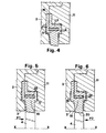
- the seal 9 is as follows. As shown in Figure 4, the seal 9 is mounted in the groove 10. The flange 16 disposed in the narrow part 10b of the groove 10 is clamped between the valve body 2 and the retaining ring 11, ensuring the fixing the seal 9 in its groove 10. Clearances, both axial j1 and j2 as radial j3, are provided between the solid part 15 of the seal and the wide part 10a of the groove 10.
- the shutter 4 closes the axial channel 3 and that the fluid pressure is exerted on the upstream side of the shutter in the direction of arrow P1, the fluid penetrates, by the axial clearance j1, between the valve body 2 and the solid part 15 of the seal applying the face 17 of the latter against the corresponding bearing face formed by the retaining ring 11, and tends to deform the shutter 4 in the direction of the arrow P1. Due to this deformation, the massive part 15 of the seal is compressed between the shutter 4 and the elastic ring 28, which prevents it from creeping. A good seal is thus obtained between the seal and the shutter.
- annular collar 16 is no longer radial, but axial, in the extension of the external face 19 of the solid part of the joint.
- one of the tongues 29, 30 constituting the flange 16 is provided with a heel 31 perpendicular to said tongue, ensuring better attachment of the seal 9 on the valve body.
- the radial width of the cavity 23 formed inside the solid part 15 of the seal is greater than the thickness of the elastic ring 28 disposed in this cavity.
- the solid part 15 can pivot, under the effect of the pressure of the fluid, by carrying out a rotational movement around the elastic ring 28 which brings the surface frustoconical 18a of the seal in contact with the corresponding surface 10C of the groove 10. This results in an increase in the seal-shutter contact pressure which increases the seal.
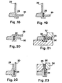
- FIG. 12 The different phases of the manufacture of the seal object of the invention are shown in Figures 12 to 14.
- an annular ring 32 is produced, the meridian section of which is shown in FIG. 12.
- This ring has a solid part 15 provided with a shoulder 21, an axial groove 23 , an axial tongue 29 and a radial tongue 30.
- an elastic ring 28 the volume of which is very slightly less than that of the groove 23, is inserted therein, as shown in FIG. 13.
- the axial tongue 29 is folded down in the direction of arrow F, as shown in FIG. 14, so that it comes to bear against the radial tongue 30, the association of the two tongues 29 and 30 forming the annular collar 16. This drawdown is carried out as follows:
- the ring 32 provided with the elastic ring 28, is placed, as shown in Figure 15, on an annular heating plate 33 which matches its external shape.
- a heating form 34 bearing on the plate 33, is disposed inside the machined ring 32.
- the plate 33 and the form 34 are hollow and their heating is ensured either by the circulation of a hot fluid, or at means of electrical resistances.
- the plate 33 and the form 34 are heated to between 250 and 300 ° C, the temperature chosen depending on the nature of the material constituting the ring 32, a fluorinated hydrocarbon polymer pure or mixed with carbon powder or steel powder stainless.
- the ring 32 is heated by thermal conduction by the plate 33 and the shape 34 which at the same time ensure its maintenance.
- a tool 35 of frustoconical shape of revolution, coaxial with the ring 32, heated to the same temperature as the plate 33 and the shape 34, is engaged inside the cylinder formed by the axial tongue 30 and moved by a movement of translation along the axis XX in the direction indicated by the arrow D.
- the axlale tongue 29 deforms outwards until it comes to occupy an intermediate position as shown in Figure 16. In this position, the tongue 29 is inclined by about 40 ° on the horizontal and is in contact over its entire length with the frustoconical part of the tool 35.
- annular flange 16 is axial
- annular ring such as that shown in Figure 22, whose axial tabs 29, 30 are parallel and define a groove in which the elastic ring 28 is inserted.
- the external tongue 30 is pushed back by a heating tool in the form of a circular crown 38, against the internal tongue 29 held stationary to form an axial direction collar ( figure 23).
Landscapes
- Engineering & Computer Science (AREA)
- General Engineering & Computer Science (AREA)
- Mechanical Engineering (AREA)
- Lift Valve (AREA)
- Sealing Devices (AREA)
Applications Claiming Priority (2)
| Application Number | Priority Date | Filing Date | Title |
|---|---|---|---|
| FR8410289 | 1984-06-27 | ||
| FR8410289A FR2566871B1 (fr) | 1984-06-27 | 1984-06-27 | Joint d'etancheite pour vanne a obturateur rotatif et son procede de fabrication |
Publications (2)
| Publication Number | Publication Date |
|---|---|
| EP0166286A1 EP0166286A1 (fr) | 1986-01-02 |
| EP0166286B1 true EP0166286B1 (fr) | 1988-08-10 |
Family
ID=9305588
Family Applications (1)
| Application Number | Title | Priority Date | Filing Date |
|---|---|---|---|
| EP85107099A Expired EP0166286B1 (fr) | 1984-06-27 | 1985-06-08 | Joint d'étanchéité pour vanne à obturateur rotatif et son procédé de fabrication |
Country Status (6)
| Country | Link |
|---|---|
| US (1) | US4638976A (ja) |
| EP (1) | EP0166286B1 (ja) |
| JP (1) | JPS61248967A (ja) |
| CA (1) | CA1267401A (ja) |
| DE (1) | DE3564327D1 (ja) |
| FR (1) | FR2566871B1 (ja) |
Families Citing this family (13)
| Publication number | Priority date | Publication date | Assignee | Title |
|---|---|---|---|---|
| NL8401311A (nl) * | 1984-04-24 | 1985-11-18 | Philips Nv | Ladingsgekoppelde halfgeleiderinrichting met dynamische besturing. |
| JPH01188772A (ja) * | 1988-01-21 | 1989-07-28 | Akira Oshima | バタフライ弁の正逆両圧シール装置 |
| IT1294045B1 (it) * | 1997-04-11 | 1999-03-15 | Bruno Tubaro | Valvola a farfalla. |
| TWI372066B (en) | 2003-10-01 | 2012-09-11 | Wyeth Corp | Pantoprazole multiparticulate formulations |
| US7261276B1 (en) * | 2004-07-14 | 2007-08-28 | Taylor Innovations, L.L.C. | Flow regulator valve |
| US7544293B2 (en) | 2005-09-26 | 2009-06-09 | Semba Inc. | Valve and process for interrupted continuous flow chromatography |
| DK3094123T3 (da) | 2006-03-21 | 2020-01-20 | Ericsson Telefon Ab L M | Målingsunderstøttet dynamisk frekvensgenanvendelse i cellulære telekommunikationsnetværk |
| US20090159827A1 (en) * | 2007-12-20 | 2009-06-25 | Tyco Valves & Controls Lp | Rotary gate valve |
| US20090184279A1 (en) * | 2008-01-23 | 2009-07-23 | Buckhorn Rubber Products, Inc. | Wedge and covered insert assembly |
| ES1074118Y (es) * | 2011-03-02 | 2011-06-17 | Angodos S L | " valvula de mariposa " |
| US9927034B2 (en) * | 2015-08-25 | 2018-03-27 | Mueller International, Llc | Valve seat stiffener |
| JP6776866B2 (ja) * | 2016-12-15 | 2020-10-28 | 株式会社デンソー | バルブ装置、および、バルブ装置の製造方法 |
| DE102021212267A1 (de) | 2021-10-29 | 2023-05-04 | Robert Bosch Gesellschaft mit beschränkter Haftung | Drosselklappenanordnung und Brennstoffzellensystem |
Family Cites Families (11)
| Publication number | Priority date | Publication date | Assignee | Title |
|---|---|---|---|---|
| DE1500093A1 (de) * | 1965-09-25 | 1969-05-08 | Schmitz & Schulte Hochdruck | Drosselklappe,Absperrklappe od.dgl. fuer gasfoermige und/oder fluessige Medien |
| GB1203029A (en) * | 1966-11-08 | 1970-08-26 | Saunders Valve Co Ltd | Butterfly valves for the control of fluids |
| US3486733A (en) * | 1967-09-01 | 1969-12-30 | Jamesbury Corp | Seat ring for ball valves |
| US3734457A (en) * | 1972-02-22 | 1973-05-22 | Dezurik Corp | Pressure biased butterfly valve seal |
| CA1059494A (en) * | 1977-04-20 | 1979-07-31 | Richard Liberman | Floating seat butterfly valve |
| US4120482A (en) * | 1977-06-16 | 1978-10-17 | Derek Michael Cox | Fluid seal |
| US4289296A (en) * | 1979-03-23 | 1981-09-15 | Xomox Corporation | Bidirectional axially pliant pressure assisted seat for a valve |
| US4266752A (en) * | 1979-03-30 | 1981-05-12 | Mcc Flowseal, A Unit Of Mark Controls Corporation | Seal structure |
| US4304392A (en) * | 1980-03-10 | 1981-12-08 | Crane Co. | Sealing means |
| US4396199A (en) * | 1981-05-15 | 1983-08-02 | Honeywell Inc. | Fluid pressure sealing member for a valve |
| US4398695A (en) * | 1981-12-29 | 1983-08-16 | Mcc Flowseal | Metal seal structure |
-
1984
- 1984-06-27 FR FR8410289A patent/FR2566871B1/fr not_active Expired
-
1985
- 1985-06-08 DE DE8585107099T patent/DE3564327D1/de not_active Expired
- 1985-06-08 EP EP85107099A patent/EP0166286B1/fr not_active Expired
- 1985-06-24 US US06/748,062 patent/US4638976A/en not_active Expired - Lifetime
- 1985-06-26 CA CA000485390A patent/CA1267401A/fr not_active Expired - Lifetime
- 1985-06-26 JP JP60140105A patent/JPS61248967A/ja active Granted
Also Published As
| Publication number | Publication date |
|---|---|
| DE3564327D1 (en) | 1988-09-15 |
| JPH0141866B2 (ja) | 1989-09-07 |
| JPS61248967A (ja) | 1986-11-06 |
| FR2566871A1 (fr) | 1986-01-03 |
| US4638976A (en) | 1987-01-27 |
| CA1267401A (fr) | 1990-04-03 |
| EP0166286A1 (fr) | 1986-01-02 |
| FR2566871B1 (fr) | 1986-12-19 |
Similar Documents
| Publication | Publication Date | Title |
|---|---|---|
| EP0166286B1 (fr) | Joint d'étanchéité pour vanne à obturateur rotatif et son procédé de fabrication | |
| EP0213998B1 (fr) | Bagues d'étanchéité de type radial et procédé de réalisation de telles bagues | |
| EP0161149B1 (fr) | Dispositif de racccordement étanche | |
| EP1023549B1 (fr) | Joint statique d'etancheite | |
| FR2617923A1 (fr) | Palier spherique et son procede de fabrication | |
| EP0368734A1 (fr) | Outillage pour le moulage de panneaux auto-raidis en matériau composite | |
| EP0003091A1 (fr) | Joint annulaire | |
| BE1001957A6 (fr) | Assemblage de palier en forme de l. | |
| EP0667207A1 (fr) | Procédé d'obtention d'une pièce circulaire métallique renforcée par des fibres | |
| FR3002995A1 (fr) | Agencement de palier pour un arbre, en particulier dans une unite de soupape, unite de soupape equipee d'un tel agencement de palier et procede pour sa fabrication | |
| EP3152027B1 (fr) | Procédé de fabrication de roue dentée avec cerclage de renfort | |
| FR2677723A1 (fr) | Dispositif de liaison elastique entre deux pieces, procede de fabrication de ce dispositif, et installation pour la mise en óoeuvre de ce procede. | |
| FR2787155A1 (fr) | Agencement d'etancheite pour un joint homocinetique, et procede de fabrication correspondant | |
| FR2859776A1 (fr) | Dispositif d'etancheite d'une tige ou d'un arbre monte a l'interieur d'un corps | |
| EP0490800A1 (fr) | Cylindre pour la coulée continue sur un ou entre deux cylindres. | |
| FR2620077A1 (fr) | Procede de fabrication de couvercles de protection d'organes pour moteurs de vehicules automobiles, par injections successives de polymere et d'elastomere et couvercle obtenu par ce procede | |
| EP0251950B1 (fr) | Dispositif d'étanchéité pour assemblage à faces planes parallèles et joints d'étanchéité correspondants | |
| EP3490787B1 (fr) | Moule de vulcanisation pour pneumatique et procédé d'assemblage des garnitures du moule. | |
| EP0538113B1 (fr) | Rouleaux conducteurs de courant notamment pour lignes d'électrolyse | |
| FR2874074A1 (fr) | Dispositif d'etancheite pour l'etancheification au niveau de leur bout de deux elements de construction tubulaire | |
| FR2636694A1 (fr) | Butee d'embrayage avec plaque d'appui metallique composite | |
| WO1981002451A1 (fr) | Element de palier a bague de centrage et procede de centrage d'un arbre | |
| WO2022184991A1 (fr) | Elément tubulaire fileté à segment | |
| FR2766550A1 (fr) | Conduite ayant au moins une extremite formant section de raccordement, procede de realisation de la section de raccordement, et dispositif de mise en oeuvre du procede | |
| FR2784438A1 (fr) | Joint statique metallique a haute temperature |
Legal Events
| Date | Code | Title | Description |
|---|---|---|---|
| PUAI | Public reference made under article 153(3) epc to a published international application that has entered the european phase |
Free format text: ORIGINAL CODE: 0009012 |
|
| AK | Designated contracting states |
Designated state(s): BE DE GB IT LU NL |
|
| 17P | Request for examination filed |
Effective date: 19860129 |
|
| 17Q | First examination report despatched |
Effective date: 19860806 |
|
| R17C | First examination report despatched (corrected) |
Effective date: 19870325 |
|
| RAP1 | Party data changed (applicant data changed or rights of an application transferred) |
Owner name: G.R.I.- SAPAG |
|
| GRAA | (expected) grant |
Free format text: ORIGINAL CODE: 0009210 |
|
| AK | Designated contracting states |
Kind code of ref document: B1 Designated state(s): BE DE GB IT LU NL |
|
| ITF | It: translation for a ep patent filed |
Owner name: JACOBACCI & PERANI S.P.A. |
|
| GBT | Gb: translation of ep patent filed (gb section 77(6)(a)/1977) | ||
| REF | Corresponds to: |
Ref document number: 3564327 Country of ref document: DE Date of ref document: 19880915 |
|
| PLBE | No opposition filed within time limit |
Free format text: ORIGINAL CODE: 0009261 |
|
| STAA | Information on the status of an ep patent application or granted ep patent |
Free format text: STATUS: NO OPPOSITION FILED WITHIN TIME LIMIT |
|
| 26N | No opposition filed | ||
| ITTA | It: last paid annual fee | ||
| EPTA | Lu: last paid annual fee | ||
| PGFP | Annual fee paid to national office [announced via postgrant information from national office to epo] |
Ref country code: GB Payment date: 20000608 Year of fee payment: 16 |
|
| PGFP | Annual fee paid to national office [announced via postgrant information from national office to epo] |
Ref country code: DE Payment date: 20000614 Year of fee payment: 16 |
|
| PGFP | Annual fee paid to national office [announced via postgrant information from national office to epo] |
Ref country code: LU Payment date: 20000626 Year of fee payment: 16 |
|
| PGFP | Annual fee paid to national office [announced via postgrant information from national office to epo] |
Ref country code: NL Payment date: 20000630 Year of fee payment: 16 |
|
| PGFP | Annual fee paid to national office [announced via postgrant information from national office to epo] |
Ref country code: BE Payment date: 20000803 Year of fee payment: 16 |
|
| PG25 | Lapsed in a contracting state [announced via postgrant information from national office to epo] |
Ref country code: LU Free format text: LAPSE BECAUSE OF NON-PAYMENT OF DUE FEES Effective date: 20010608 Ref country code: GB Free format text: LAPSE BECAUSE OF NON-PAYMENT OF DUE FEES Effective date: 20010608 |
|
| PG25 | Lapsed in a contracting state [announced via postgrant information from national office to epo] |
Ref country code: BE Free format text: LAPSE BECAUSE OF NON-PAYMENT OF DUE FEES Effective date: 20010630 |
|
| BERE | Be: lapsed |
Owner name: G.R.I.- SAPAG Effective date: 20010630 |
|
| PG25 | Lapsed in a contracting state [announced via postgrant information from national office to epo] |
Ref country code: NL Free format text: LAPSE BECAUSE OF NON-PAYMENT OF DUE FEES Effective date: 20020101 |
|
| GBPC | Gb: european patent ceased through non-payment of renewal fee |
Effective date: 20010608 |
|
| NLV4 | Nl: lapsed or anulled due to non-payment of the annual fee |
Effective date: 20020101 |
|
| PG25 | Lapsed in a contracting state [announced via postgrant information from national office to epo] |
Ref country code: DE Free format text: LAPSE BECAUSE OF NON-PAYMENT OF DUE FEES Effective date: 20020403 |