EP0166262B1 - Rear projection screen - Google Patents
Rear projection screen Download PDFInfo
- Publication number
- EP0166262B1 EP0166262B1 EP85106693A EP85106693A EP0166262B1 EP 0166262 B1 EP0166262 B1 EP 0166262B1 EP 85106693 A EP85106693 A EP 85106693A EP 85106693 A EP85106693 A EP 85106693A EP 0166262 B1 EP0166262 B1 EP 0166262B1
- Authority
- EP
- European Patent Office
- Prior art keywords
- rear projection
- projection screen
- light
- crest
- angle
- Prior art date
- Legal status (The legal status is an assumption and is not a legal conclusion. Google has not performed a legal analysis and makes no representation as to the accuracy of the status listed.)
- Expired
Links
Images





Classifications
-
- G—PHYSICS
- G03—PHOTOGRAPHY; CINEMATOGRAPHY; ANALOGOUS TECHNIQUES USING WAVES OTHER THAN OPTICAL WAVES; ELECTROGRAPHY; HOLOGRAPHY
- G03B—APPARATUS OR ARRANGEMENTS FOR TAKING PHOTOGRAPHS OR FOR PROJECTING OR VIEWING THEM; APPARATUS OR ARRANGEMENTS EMPLOYING ANALOGOUS TECHNIQUES USING WAVES OTHER THAN OPTICAL WAVES; ACCESSORIES THEREFOR
- G03B21/00—Projectors or projection-type viewers; Accessories therefor
- G03B21/54—Accessories
- G03B21/56—Projection screens
- G03B21/60—Projection screens characterised by the nature of the surface
- G03B21/62—Translucent screens
- G03B21/625—Lenticular translucent screens
Definitions
- the present invention relates to a rear projection screen according to the preamble of claim 1, suitable for use as, for example, a screen for a video projector.
- the present invention relates more particularly to a rear projection screen having a greater angle of field of view on the viewing side and an increased brightness.
- Rear projection screens have been widely available for video projectors, microfilm readers and computer display systems, and various studies and attempts have been made for improving the light transmitting characteristics of the rear projection screen for attaining greater angle of field of view, higher contrast and higher resolution.
- a rear projection screen according to the preamble of claim 1 is known.
- This projection screen is made of transparent sheet formed therein with conical or parabolic projections.
- the projections have reflective lateral surfaces, i.e. flanks which are so inclined in order to form in selected areas a total internal reflection surface along the medium interface between ambient air and said flank.
- These projections have peculiar axes that gradually vary from the center part to the peripheral part of the rear projection screen. Due to the shapes of projections which are conical or parabolic, the light rays passing through the rear projection screen and being reflected by the lateral surfaces are defused both vertically and horizontally.
- This lenticulated surface is effective in diffusing the light impinging thereon. More specifically, a lenticulated surface having a multiplicity of minute vertically extending cylindrical lenses arranged continually on a vertical plane laterally diffuses the light, while the lenticulated surface having a multiplicity of minute horizontally extending cylindrical lenses arranged continually on a vertical plane longitudinally diffuses the light.
- this lenticulated surface is used as a screen, the maximum diffusion angle is varied largely depending on whether the lenticulated surface is faced to the incident light, i.e. towards the light source or to the viewer. Namely, as is known to those skilled in the art, it is possible to obtain a greater diffusion angle when the surface is faced to the light source than when the same is faced to the viewer.
- each lenticule of the lenticulated surface of the kind described has a circular cross-section so that the angle of diffusion of light is considerably small.
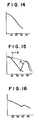
- the brightness is drastically lowered disadvantageously in the region of viewing angles exceeding 30°, as will be seen from Fig. 14.
- This reduction of brightness causes not only the problem that the picture surface is darkend when viewed from the region out of the viewing angle of 30° but also a problem that the picture surface becomes completely invisible due to a surface reflection in bright circumstance under the influence of ambient light.
- the first step of increasing the overall brightness with a large angle of field of view is the orientation of the lens units in vertical direction.
- the additional measure according to the subject matter of the present invention resides in that all light rays which impinge on the flanks and which are internally reflected are directed in such a way to the convex surfaces that they essentially do not overlap the light rays going directly through said convex surface.
- the light intensity can be distributed more uniformly than it is the case with the prior art. By this, not only the brightness level becomes more pleasant. Additionally, the fabrication of the mould for the screen and the manufacturing process of the screen becomes easier, since the rear projection screen according to the invention uses uniform lens units and the lenticular surface has a uniform pattern thereover having no part which is locally different in pattern from the remaining part.
- Fig. 17 light rays diverging from a projector 172 impinge upon the rear surface of a rear projection screen 171 through a Fresnel lens 173 which converts the diverging light rays into parallel light rays.
- the light rays transmitted through the medium of the rear projection screen 171 in parallel relation are dispersed from the front surface of the rear projection screen 171 in a suitable viewing angle.
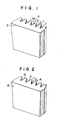
- Figs. 1 to 5 are perspective views of rear projection screens embodying the invention.
- the rear projection screen of the invention is provided on its viewing side surface a lenticulated surface formed with a plurality of lenticules each having a crest 1 and troughs 2 interconnected by intermediate flanks 3.
- the flank 3 is provided at least a portion thereof with a total reflecting surface such that the light rays impinging thereto are totally reflected and then emanate through the crest 1.
- Figs. 1 to 5- show practical embodiments of the rear projection screen of the invention. More specifically, Fig. 1 shows an embodiment in which a most part of each flank 3 constitutes a total reflecting surface 31, leaving small portions of non-reflecting surfaces 32.
- Fig. 1 shows an embodiment in which a most part of each flank 3 constitutes a total reflecting surface 31, leaving small portions of non-reflecting surfaces 32.
- FIG. 2 shows another embodiment in which the entire part of each flank 3 constitutes a total reflecting surface 31.
- Fig. 3 shows still another embodiment in which concaved lens surfaces 21 are formed in the troughs 2 of the embodiment shown in Fig. 1.
- Fig. 4 shows a further embodiment in which concaved lens surfaces 21 are formed in the troughs 2 of the embodiment shown in Fig. 2.
- Fig. 5 shows a further embodiment in which, in place of the concaved lens surfaces 21 in the embodiment shown in Fig. 4, convexed lens surfaces 22 are formed.
- the projecting side surface B of the rear projection screen is flat and smooth. It is, however, effective to form a Fresnel lens on the projecting side surface.
- Figs. 6 and 7 are sectional views of light embodiments in which a Fresnel lens is formed on the projecting side surface of the rear projection screen. More specifically, Fig. 6 shows a still further embodiment in which a Fresnel lens 4 is formed on the projecting side surface B of the embodiment shown in Fig. 3, while Fig. 7 shows a still further embodiment in which a Fresnel lens 4 is formed on the projecting side surface B of the embodiment shown in Fig. 5.
- the Fresnel lens in this case is generally a circular Fresnel lens and the focal length thereof varies depending on applications of the screen.
- the focal length f is usually between 1.0 and 1.2 m.
- the Fresnel lens 4 can also be incorporated in the embodiments shown in Figs. from 1 through 4.
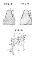
- Figs. 8 and 9 show still further embodiments improved to increase the contrast of image on the rear projection screen.
- a light absorbing layer 5 is formed on the total reflecting surface 31.
- Fig. 9 shows an light embodiment in which, in order to prevent the absorption loss in the light absorbing layer 5, a coating layer 6 of a substance having a smaller refractive index than the medium is formed beforehand on the total reflecting surface and then the light absorbing layer 5 is formed on the coating layer 6.
- a coating layer 6 of a substance having a smaller refractive index than the medium is formed beforehand on the total reflecting surface and then the light absorbing layer 5 is formed on the coating layer 6.
- the total reflecting surface 31 which does not directly transmit the light therethrough to the viewing side surface A, so that the contrast of the image on the rear projection screen is improved considerably.
- the essential feature of the invention resides in the formation of a specific total reflecting surface 31 in each flank 3 of the lenticule.
- the light transmission characteristics of the flank having the total reflecting surface will be explained hereinunder with reference to Figs. 10 through 13.
- Fig. 10 is an enlarged view of a portion of the lenticulated surface of a rear projection screen in accordance with the invention.
- the flank 3 is provided with a total reflecting surface 31 and non-reflecting surfaces 32.
- the non-reflecting surfaces 32 are intended for facilitating removal of the medium from the mold in the process of production of the screen.
- the non-reflecting surface 32 is formed in parallel with the optical axis or at an inclination angle of 1 to 5° to the optical axis.
- the total reflecting surface 31 is adapted to make a total reflection of a part of the light rays impinging on the medium and to make the same emanate from the crest 1. It is necessary, however, that the totally reflected light and the light directly impinging on the crest 1 are not totally reflected by the medium interface of the crest 1.
- the angle ⁇ of inclination of the total reflecting surface 31 to the optical axis is determined by the refractive index n of the medium.
- n the refractive index
- light rays Y 1 and X 1 run in parallel with the normal axis N.
- the light ray Y 1 out of these two rays impinges on the total reflecting surface 31 at an angle ⁇ and is totally reflected and emanates through the crest 1 as a ray Y z .
- the total-reflected light intersects the normal axis N at an angle 2 ⁇ and emanates through the crest 1.
- the angle a of inclination of the total reflecting surface 31 is thus determined. Assuming that the medium is an acrylic resin having a refractive index n of 1.492, the angle a is calculated as follows:
- the angle a must be greater than about 69°.
- the angle 28 of the ray passing through the crest 1 approaches the critical angle 42.09°, closely, the possibility of total reflection at the medium interface of the crest 1 is increased unfavourably, so that the angle 28 is preferably smaller than the critical angle.
- the angle a preferably approximates 90°.
- a too large angle a makes the height of the crest excessively large in comparison with its width so as to make it difficult to form such a crest.
- the angle a is limited also from this point, and is preferably made small in order to facilitate the formation of the crest.
- the angle a is preferably selected to range between 70° and 80° when an acrylic resin is used as the medium (screen material).
- This angle is the angle of incidence of the ray X, parallel to the ray Y, and passing the point Q. Therefore, the design should be made to meet the following condition of
- the rays X 1 and X 2 which pass in the medium towards both marginal ends of the portion x of the crest 1 run straight and are refracted as illustrated when leaving the convexed lens surface 11 of the crest 1, while the rays Z 1 and Z 2 passing through both ends of the trough 2 are diffused.
- most portion of the rays coming into both ends of the portion Y of each flank 3, i.e. the rays in the region between Y 1 and Y 2 or between Y 1 , and Y 2 are reflected on each total reflecting surface 31 and emanates through the convexed lens surface 11 on the crest 1.
- the uniformity of brightness within the region of projection angle of the projected rays is varied depending on the direction of viewing of the picture element.
- the rays passing through the convexed lens surface 11 are diffused within the range w after emanating through the crest 1, as in the cases of rays X 1 and X 2 .
- the rays coming into the total reflecting surface 31, i.e. the rays between the rays Y 1 and Y2 are totally reflected and emanate through the crest 1 as strong light rays within the range cp.
- the brightness of the resultant rays is drastically lowered in the angle region exceeding 30° from the center line of the crest 11.
- the rays cp reflecting from the total reflecting surface 31 and then emanating from the crest 11 form a strong light which represents brightness characteristics ⁇ shown in Fig. 15.
- This ray advantageously compensates for the reduction of brightness in the abovemen- tioned characteristics (w + ⁇ ), thereby to further uniformalize the brightness within the reasonable viewing angle range.
- the curve shown by broken line in Fig. 15 shows total brightness characteristics due to ⁇ , ⁇ and ⁇ with the assistance of a light diffusing means which will be mentioned hereinunder.
- the most suitable optical system for obtaining these characteristics can be selected by properly selecting optimum values to factors such as the height of the flank 3, pitches P, P 1 and P 2 of the lenticules, and the focal lengths of the convexed lens surface 11 and the concaved lens surface 21.
- Fig. 13 shows the optical system of the rear projection screen as shown in Fig. 7.
- the rays in the range Y 1 and Y 2 among the parallel light rays coming from the projecting side are totally reflected and emanate, as cp, from the crest.
- the rays in the range between Z, and Z 2 are diffused as ⁇ after passing the focal point.
- the rays in the range between X 1 and X 2 are diffused as illustrated with the region w.
- the rays between Y 2 and X 1 and the rays between X 2 and Y 2 are made to partially emanate and partially repeat reflection and refraction before emanation to the outside.
- the rays ⁇ from the total reflecting surface 31 serves to increase the angle of field of vision and provides, in combination with the other rays ⁇ and w, brightness characteristics as shown in Fig. 16.
- the material of the medium is stated as being an acrylic resin. This is because the acrylic resin exhibits superior optical properties and easy processability. It is possible, however, to use other materials such as vinyl chloride resins, polycarbonate resins, olefin resins, styrene resins and so forth. With these synthetic resins, the rear projection screen of the invention can be produced by extrusion, heat press, injection molding and so forth.
- the width P, of the crest 1 is selected to range between 0.2 and 1.5 mm, while the width P 2 of the trough 2 is selected to be between 0.3 and 1.5 mm.
- the pitch P is selected to fall between 0.5 and 3 mm, while the height H is selected to range between 0.2 and 2 mm.
- the rear projection screen of the invention can easily be formed even when the lenticulated surface has a narrow or restricted trough 2 as in the case of screens shown in Figs. 1 and 2. From the view point of manufacture, however, it is preferred that the lens surface is formed also in the trough 2 as in the case of the embodiments shown in Figs. 3 thru 7, because of ready removal from the mold as compared with the case where the crests are interconnected through the flank to the comparatively narrow trough 2.
- the flank 3 need not always be straight but can have a curvilinear profile.
- the medium In order to further increase the diffusion of light in both vertical and horizontal directions in the rear projection screen, it is advisable to provide the medium with additional light diffusing means. For instance, it is possible to uniformly mix and disperse in the medium one, two or more additives which are neither molten in the liquid medium such as molten acrylic resin nor make chemical reaction therewith.
- additives are inorganic diffusion agents such as Si0 2 , CaC0 3 , AI 2 0 3 , Ti0 2 , BaS0 4 , ZnO and fine powdered glass, and organic diffusion agents such as polystyrene, styrene-acrylonitrile copolymer or the like. It is also effective to form a layer containing such diffusion agents.
- minute roughness is made in the incidence surface or the surface of the crest.
- the contrast of the picture element is reduced by ambient light impinging one side surface of the screen.
- the light absorbing layer 5 inconveniently absorbs a part of the light reflected by the total reflection surface 31, although such a part is negligibly small.
- the material having smaller refractive index for example, it is possible to use a resin containing fluorine when the medium is made of an acrylic resin. It is possible to use a reflecting layer of, for example, aluminum as the coating layer 6.
- a sheet of 3 mm thick was formed from a material mainly consisting of a partially polymerized methacrylate with an additive of Si0 2 as a diffusion agent.
- a screen having lenticules on the projecting side surface as shown in Fig. 1 was formed by a heat press.
- the pitch of the lenticules was 0.75 mm
- the radius of curvature of the crest was 0.4R
- the angle a was 70°.
- the focal length f of the Fresnel lens was 1.2 m.
- Brightness characteristics of the thus formed screen were evaluated. It was confirmed that the value Go and the angle (3 and 8 and 24°, respectively.
- the screen exhibited a superior performance to make the image visible over a wide angle of field of vision which materially exceeds 55°.
- a screen was formed by a heat press to have lenticules substantially identical to those in Fig. 2 and provided in the projecting side surface thereof with a Fresnel lens similar to that of Example 1.
- the pitch and height of the lenticules were 0.7 mm, while the angle a 75°.
- the Go value and the angle (3 were 5.3 and 22°, respectively, but the screen showed good characteristics to make the image visible within the range of angle of field of vision up to 50°.
- Example 2 Using a similar sheet as in Example 1, a screen having a form substantially equal to that shown in Fig. 7 was formed.
- the pitches of the lenticules having the total reflection surfaces was 0.5 mm
- the pitch of the circular lenticules was 0.7 mm
- the height was 0.5 mm.
- the angle a and the focal length f of the Fresnel lens were 75° and 1.2 m, respectively.
- the thus obtained screen showed high Go value and large angle ⁇ which are 6.6 and 32°, respectively.
- the screen had good performance to make the image visible over a wide angle of field of vision of up to 60°, advantageously.
Landscapes
- Physics & Mathematics (AREA)
- General Physics & Mathematics (AREA)
- Overhead Projectors And Projection Screens (AREA)
- Optical Elements Other Than Lenses (AREA)
Applications Claiming Priority (4)
| Application Number | Priority Date | Filing Date | Title |
|---|---|---|---|
| JP51194/81 | 1981-04-07 | ||
| JP56051194A JPS57165830A (en) | 1981-04-07 | 1981-04-07 | Lenticular lens for screen |
| JP56090544A JPS57205727A (en) | 1981-06-12 | 1981-06-12 | Renticular lens for screen |
| JP90544/81 | 1981-06-12 |
Related Parent Applications (1)
| Application Number | Title | Priority Date | Filing Date |
|---|---|---|---|
| EP82102985.7 Division | 1982-04-06 |
Publications (2)
| Publication Number | Publication Date |
|---|---|
| EP0166262A1 EP0166262A1 (en) | 1986-01-02 |
| EP0166262B1 true EP0166262B1 (en) | 1990-07-11 |
Family
ID=26391729
Family Applications (2)
| Application Number | Title | Priority Date | Filing Date |
|---|---|---|---|
| EP85106693A Expired EP0166262B1 (en) | 1981-04-07 | 1982-04-06 | Rear projection screen |
| EP82102985A Expired EP0063317B1 (en) | 1981-04-07 | 1982-04-06 | Rear projection screen |
Family Applications After (1)
| Application Number | Title | Priority Date | Filing Date |
|---|---|---|---|
| EP82102985A Expired EP0063317B1 (en) | 1981-04-07 | 1982-04-06 | Rear projection screen |
Country Status (5)
| Country | Link |
|---|---|
| US (1) | US4418986A (da) |
| EP (2) | EP0166262B1 (da) |
| CA (1) | CA1181272A (da) |
| DE (2) | DE3280211D1 (da) |
| DK (1) | DK156019C (da) |
Families Citing this family (53)
| Publication number | Priority date | Publication date | Assignee | Title |
|---|---|---|---|---|
| JPS58145933A (ja) * | 1982-02-25 | 1983-08-31 | Mitsubishi Rayon Co Ltd | 背面投影スクリ−ン |
| US4509823A (en) * | 1982-10-15 | 1985-04-09 | Dai Nippon Insatsu Kabushiki Kaisha | Rear projection screen |
| JPS59121034A (ja) * | 1982-12-27 | 1984-07-12 | Mitsubishi Rayon Co Ltd | 透過型スクリ−ン |
| DK156188C (da) * | 1983-05-10 | 1989-11-27 | Scan Screen Production A S | Transparent baglysprojektionsskaerm |
| JPS6075826A (ja) * | 1983-06-13 | 1985-04-30 | Mitsubishi Rayon Co Ltd | 背面投影スクリーン |
| DK151320C (da) * | 1983-10-12 | 1988-05-09 | Scan Screen | Transparent baglysprojektionsskaerm |
| US4548469A (en) * | 1984-06-07 | 1985-10-22 | Mitsubishi Rayon Co., Ltd. | Rear projection screen |
| JPS6169867A (ja) * | 1984-09-13 | 1986-04-10 | Mitsubishi Rayon Co Ltd | シリカ微粒子含有樹脂組成物 |
| JPS61208041A (ja) * | 1985-03-11 | 1986-09-16 | Mitsubishi Rayon Co Ltd | 背面投影スクリ−ン |
| US4708435A (en) * | 1986-10-30 | 1987-11-24 | Mitsubishi Rayon Co., Ltd. | Rear projection screen |
| US4880292A (en) * | 1987-07-24 | 1989-11-14 | Minolta Camera Kabushiki Kaisha | Transmission viewing screen of image projector apparatus |
| DK160593C (da) * | 1988-09-28 | 1991-09-09 | Dainippon Printing Co Ltd | Baglysprojektionsskaerm |
| JPH02135332A (ja) * | 1988-11-16 | 1990-05-24 | Pioneer Electron Corp | 背面投写型プロジェクションテレビのレンチキュラーレンズ |
| DK687288A (da) * | 1988-12-09 | 1990-06-10 | Dainippon Printing Co Ltd | Baglysprojektionsskaerm |
| DK174788B1 (da) * | 1989-05-08 | 2003-11-10 | Dainippon Printing Co Ltd | Baglysprojektionsskærm |
| NL8902112A (nl) * | 1989-08-22 | 1991-03-18 | Philips Nv | Doorzichtprojektiescherm en doorzichtprojektiesysteem voorzien van een dergelijk scherm. |
| US5095629A (en) * | 1991-01-31 | 1992-03-17 | Spectra-Physics Laserplane, Inc. | Laser beam target |
| US20030206342A1 (en) * | 1993-05-12 | 2003-11-06 | Bright View Technologies, Inc. | Micro-lens array based light transmission screen |
| US6788460B2 (en) * | 1998-04-15 | 2004-09-07 | Duke University | Projection screen apparatus |
| US5428476A (en) * | 1994-04-07 | 1995-06-27 | Stewart Filmscreen Corporation | Wide angle rear projection lenticular lens system |
| AU2152097A (en) * | 1996-03-18 | 1997-10-10 | Scan Vision Screen Aps | Rear projection screen |
| US6280063B1 (en) * | 1997-05-09 | 2001-08-28 | 3M Innovative Properties Company | Brightness enhancement article |
| US6304378B1 (en) | 1997-07-04 | 2001-10-16 | Scan Vision Screen Aps | Rear projection screen assembly having a projection screen with reflecting rib lenses |
| US6829087B2 (en) * | 1998-04-15 | 2004-12-07 | Bright View Technologies, Inc. | Micro-lens array based light transmitting screen with tunable gain |
| US6816306B2 (en) * | 1998-04-15 | 2004-11-09 | Bright View Technologies Inc. | Micro-lens array based light transmitting screen with high resolution and low imaging artifacts |
| US6967779B2 (en) * | 1998-04-15 | 2005-11-22 | Bright View Technologies, Inc. | Micro-lens array with precisely aligned aperture mask and methods of producing same |
| US6301417B1 (en) | 1998-08-31 | 2001-10-09 | Brookhaven Science Associates | Ultrathin optical panel and a method of making an ultrathin optical panel |
| US6400876B1 (en) | 1998-08-31 | 2002-06-04 | Brookhaven Science Associates | Ultrathin optical panel and a method of making an ultrathin optical panel |
| US6622392B1 (en) | 1999-03-19 | 2003-09-23 | Laser Alignment, Inc. | Target with diffractive elements for use with laser beam generating devices |
| DE19923226A1 (de) * | 1999-05-20 | 2000-11-23 | Zumtobel Staff Gmbh | Optisches Element mit Mikroprismenstruktur zur Umlenkung von Lichtstrahlen |
| MXPA01002169A (es) * | 1999-07-02 | 2003-03-27 | Thomson Licensing Sa | Cubierta de lente lenticular para pantalla de proyeccion por transparencia. |
| US6417966B1 (en) | 1999-07-07 | 2002-07-09 | 3M Innovative Properties Company | Rear projection screen using internal reflection |
| US6535333B1 (en) | 2000-11-21 | 2003-03-18 | 3M Innovative Properties Company | Optical system with reduced color shift |
| US6535674B2 (en) | 2000-12-15 | 2003-03-18 | Scram Technologies, Inc. | High contrast front projection display panel and a method of making a high contrast front projection display panel |
| US6819486B2 (en) * | 2001-01-17 | 2004-11-16 | 3M Innovative Properties Company | Projection screen having elongated structures |
| US6631030B2 (en) | 2001-03-30 | 2003-10-07 | 3M Innovative Properties Company | Projection screens and methods for making such projection screens |
| US20030163367A1 (en) * | 2001-04-06 | 2003-08-28 | 3M Innovative Properties Company | Screens and methods for displaying information |
| US6870670B2 (en) | 2001-04-06 | 2005-03-22 | 3M Innovative Properties Company | Screens and methods for displaying information |
| US6571044B2 (en) | 2001-05-18 | 2003-05-27 | Scram Technologies, Inc. | High contrast display panel and a method of making a high contrast display panel |
| US6755534B2 (en) | 2001-08-24 | 2004-06-29 | Brookhaven Science Associates | Prismatic optical display |
| WO2003087927A2 (en) * | 2002-04-12 | 2003-10-23 | Duke University | Projection screen apparatus |
| WO2004085067A1 (ja) * | 2003-03-25 | 2004-10-07 | Dai Nippon Printing Co. Ltd. | 拡散シート、それを備えた透過型スクリーン、拡散シート用成形型の作製方法および拡散シートの製造方法 |
| JP4527967B2 (ja) * | 2003-11-17 | 2010-08-18 | オリンパス株式会社 | 焦点板原盤及びその製造方法 |
| US7187831B2 (en) * | 2004-04-26 | 2007-03-06 | Brookhaven Science Associates | Optical panel system including stackable waveguides |
| WO2007058810A2 (en) * | 2005-11-15 | 2007-05-24 | Arkema France | White light diffusing thermoplastic composition |
| KR20100027116A (ko) * | 2007-05-07 | 2010-03-10 | 쓰리엠 이노베이티브 프로퍼티즈 컴파니 | 프로젝션 스크린 |
| US20080285125A1 (en) * | 2007-05-18 | 2008-11-20 | Fujifilm Manufacturing U.S.A. Inc. | Optical panel for front projection under ambient lighting conditions |
| US7923675B2 (en) * | 2007-06-06 | 2011-04-12 | 3M Innovative Properties Company | Projection system having avirtual mask |
| US7496263B2 (en) * | 2007-06-07 | 2009-02-24 | Fujifilm Manfacturing U.S.A. Inc. | Thermosetting optical waveguide coating |
| US20080305255A1 (en) * | 2007-06-07 | 2008-12-11 | Fujifilm Manufacturing U.S.A. Inc. | Optical waveguide coating |
| CN101470221B (zh) * | 2007-12-26 | 2011-01-19 | 颖台科技股份有限公司 | 扩散板与使用该扩散板的背光模块 |
| US9557445B2 (en) | 2015-02-24 | 2017-01-31 | Arkema France | Optical diffusion blend materials for LED lighting |
| EP3262461A4 (en) | 2015-02-24 | 2018-10-03 | Arkema France | High efficiency diffusion lighting coverings |
Family Cites Families (11)
| Publication number | Priority date | Publication date | Assignee | Title |
|---|---|---|---|---|
| CH98590A (de) | 1921-05-28 | 1923-04-02 | Buechner Oswald | Transparent. |
| US2510344A (en) * | 1945-03-17 | 1950-06-06 | Rca Corp | Viewing screen |
| US2529701A (en) * | 1947-05-13 | 1950-11-14 | Rca Corp | Rear projection viewing screen |
| GB656651A (en) | 1947-05-13 | 1951-08-29 | Rca Corp | Improvements in rear projection viewing screen |
| US2738706A (en) * | 1952-04-04 | 1956-03-20 | Jr Harvey A Thompson | Back-lighted projection screens |
| US2870673A (en) * | 1954-11-26 | 1959-01-27 | Schwesinger Gerhard | Lenticulated rear projection screen |
| US3218924A (en) * | 1962-06-25 | 1965-11-23 | Wendell S Miller | Rear projection screen |
| US3257900A (en) * | 1963-10-25 | 1966-06-28 | Goodbar Isaac | Projection screen |
| US3279314A (en) * | 1965-10-23 | 1966-10-18 | Wendell S Miller | High contrast projection screens |
| BE792745A (fr) * | 1971-12-15 | 1973-03-30 | Freen Ltd | Ecran pour projection par transparence |
| FR2276605A1 (fr) | 1974-06-28 | 1976-01-23 | Bachelot Andre | Dispositif optique double face |
-
1982
- 1982-03-31 US US06/364,193 patent/US4418986A/en not_active Expired - Lifetime
- 1982-04-05 CA CA000400430A patent/CA1181272A/en not_active Expired
- 1982-04-06 DK DK158582A patent/DK156019C/da not_active IP Right Cessation
- 1982-04-06 EP EP85106693A patent/EP0166262B1/en not_active Expired
- 1982-04-06 DE DE8585106693T patent/DE3280211D1/de not_active Expired - Lifetime
- 1982-04-06 DE DE8282102985T patent/DE3274155D1/de not_active Expired
- 1982-04-06 EP EP82102985A patent/EP0063317B1/en not_active Expired
Also Published As
| Publication number | Publication date |
|---|---|
| US4418986A (en) | 1983-12-06 |
| DK156019B (da) | 1989-06-12 |
| EP0063317A1 (en) | 1982-10-27 |
| DE3274155D1 (en) | 1986-12-11 |
| DE3280211D1 (de) | 1990-08-16 |
| DK156019C (da) | 1989-10-16 |
| DK158582A (da) | 1982-10-08 |
| CA1181272A (en) | 1985-01-22 |
| EP0063317B1 (en) | 1986-11-05 |
| EP0166262A1 (en) | 1986-01-02 |
Similar Documents
| Publication | Publication Date | Title |
|---|---|---|
| EP0063317B1 (en) | Rear projection screen | |
| CA1180924A (en) | Rear projection screen | |
| EP0067430B1 (en) | Rear projection screen | |
| JP3655972B2 (ja) | 反射型スクリーン及び前方投影システム | |
| JP4294306B2 (ja) | 光学シート及びこれを用いたバックライトユニット | |
| CN100445868C (zh) | 菲涅尔透镜片、透射型屏幕和背面投射型显示装置 | |
| KR0144686B1 (ko) | 배면투사스크린 | |
| JPS63212925A (ja) | レンチキユラ−レンズスクリ−ン | |
| US6943948B2 (en) | Fresnel lens sheet and transmission type projection screen | |
| EP0381417A1 (en) | Rear projection screen and method of manufacturing the same | |
| US4550977A (en) | Rear projection screen | |
| KR100567418B1 (ko) | 프레넬렌즈시트, 투과형스크린 및 배면투사형 표시장치 | |
| KR890000783B1 (ko) | 후면 투사 스크린 | |
| US4548469A (en) | Rear projection screen | |
| JPS63165838A (ja) | 透過型スクリ−ン | |
| JPS6128979B2 (da) | ||
| JPS6130252B2 (da) | ||
| JPS6128978B2 (da) | ||
| JPH10293361A (ja) | 透過型スクリーン | |
| JP2004093588A (ja) | 拡散シートおよび透過型スクリーン | |
| JPS6210637A (ja) | 背面投影スクリ−ン | |
| JP2003177477A (ja) | フレネルレンズシートおよび透過型投影スクリーン | |
| JPH0387819A (ja) | 透過形投影スクリーン | |
| JPS63265235A (ja) | 透過型投影スクリ−ン | |
| JPS6385725A (ja) | 透過型スクリ−ン |
Legal Events
| Date | Code | Title | Description |
|---|---|---|---|
| PUAI | Public reference made under article 153(3) epc to a published international application that has entered the european phase |
Free format text: ORIGINAL CODE: 0009012 |
|
| AC | Divisional application: reference to earlier application |
Ref document number: 63317 Country of ref document: EP |
|
| AK | Designated contracting states |
Designated state(s): DE GB NL SE |
|
| 17P | Request for examination filed |
Effective date: 19860611 |
|
| 17Q | First examination report despatched |
Effective date: 19870519 |
|
| GRAA | (expected) grant |
Free format text: ORIGINAL CODE: 0009210 |
|
| AC | Divisional application: reference to earlier application |
Ref document number: 63317 Country of ref document: EP |
|
| AK | Designated contracting states |
Kind code of ref document: B1 Designated state(s): DE GB NL SE |
|
| REF | Corresponds to: |
Ref document number: 3280211 Country of ref document: DE Date of ref document: 19900816 |
|
| PLBI | Opposition filed |
Free format text: ORIGINAL CODE: 0009260 |
|
| 26 | Opposition filed |
Opponent name: N.V. PHILIPS' GLOEILAMPENFABRIEKEN Effective date: 19910411 |
|
| NLR1 | Nl: opposition has been filed with the epo |
Opponent name: PHILIPS GLOEILAMPENFABRIEKEN N.V. |
|
| PGFP | Annual fee paid to national office [announced via postgrant information from national office to epo] |
Ref country code: DE Payment date: 19920514 Year of fee payment: 11 |
|
| PGFP | Annual fee paid to national office [announced via postgrant information from national office to epo] |
Ref country code: GB Payment date: 19930326 Year of fee payment: 12 |
|
| PGFP | Annual fee paid to national office [announced via postgrant information from national office to epo] |
Ref country code: SE Payment date: 19930419 Year of fee payment: 12 |
|
| PGFP | Annual fee paid to national office [announced via postgrant information from national office to epo] |
Ref country code: NL Payment date: 19930430 Year of fee payment: 12 |
|
| RDAG | Patent revoked |
Free format text: ORIGINAL CODE: 0009271 |
|
| STAA | Information on the status of an ep patent application or granted ep patent |
Free format text: STATUS: PATENT REVOKED |
|
| 27W | Patent revoked |
Effective date: 19921103 |
|
| GBPR | Gb: patent revoked under art. 102 of the ep convention designating the uk as contracting state |
Free format text: 921103 |
|
| NLR2 | Nl: decision of opposition | ||
| EUG | Se: european patent has lapsed |
Ref document number: 85106693.6 Effective date: 19930707 |