EP0165373B1 - Procédé pour la transmission de télévision à bande étroite - Google Patents
Procédé pour la transmission de télévision à bande étroite Download PDFInfo
- Publication number
- EP0165373B1 EP0165373B1 EP85100541A EP85100541A EP0165373B1 EP 0165373 B1 EP0165373 B1 EP 0165373B1 EP 85100541 A EP85100541 A EP 85100541A EP 85100541 A EP85100541 A EP 85100541A EP 0165373 B1 EP0165373 B1 EP 0165373B1
- Authority
- EP
- European Patent Office
- Prior art keywords
- signal
- edges
- television
- correction
- edge
- Prior art date
- Legal status (The legal status is an assumption and is not a legal conclusion. Google has not performed a legal analysis and makes no representation as to the accuracy of the status listed.)
- Expired - Lifetime
Links
Images
Classifications
-
- H—ELECTRICITY
- H04—ELECTRIC COMMUNICATION TECHNIQUE
- H04N—PICTORIAL COMMUNICATION, e.g. TELEVISION
- H04N5/00—Details of television systems
- H04N5/14—Picture signal circuitry for video frequency region
- H04N5/20—Circuitry for controlling amplitude response
- H04N5/205—Circuitry for controlling amplitude response for correcting amplitude versus frequency characteristic
- H04N5/208—Circuitry for controlling amplitude response for correcting amplitude versus frequency characteristic for compensating for attenuation of high frequency components, e.g. crispening, aperture distortion correction
-
- H—ELECTRICITY
- H04—ELECTRIC COMMUNICATION TECHNIQUE
- H04N—PICTORIAL COMMUNICATION, e.g. TELEVISION
- H04N7/00—Television systems
- H04N7/12—Systems in which the television signal is transmitted via one channel or a plurality of parallel channels, the bandwidth of each channel being less than the bandwidth of the television signal
Definitions
- the invention relates to a method with the features specified in the preamble of claim 1.
- the invention has for its object to develop a method with the features specified in the preamble of claim 1 such that even with a further saving in bandwidth of the transmission channel, satisfactory images can still be obtained on the playback side.
- the advantages of the invention are, in particular, that the amplifier field lengths of the transmission links can be increased with little technical effort.
- the contrast transfer function which is responsible for whether the human eye finds hard, steep transitions between light and dark, which are characteristic of a sharp image, is also essential.
- a major advantage of this bandwidth reduction is the associated increase in the amplifier field length of the transmission link.
- a standard two-wire transmission path with lines of 2x0.8 mm diameter and a transmission bandwidth of 5 MHz enables an amplifier field length of 2.5 km.
- the bandwidth reduction from 5 MHz by a factor of 7 to 700 kHz enables the amplifier field length to be increased by a factor of -V-7--2.65. This means that fewer repeaters are required and the number of structural measures required is reduced. This is of considerable economic importance.
- Another advantage of the present invention is that the system can be adapted to the prevailing conditions on site. If the available amplifier field length is not fully utilized, the unused line length can be converted directly into usable bandwidth. E.g. the maximum possible extension of the amplifier field length of factor 2.65 used only with factor 2.25, this results in a usable bandwidth of 1 MHz compared to 700 kHz. This increases the picture quality.
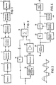
- FIG. 1 shows a block diagram of the overall system.
- the camera 1 delivers a standard video signal with a bandwidth of e.g. 5 MHz.
- the signal is first fed to a device 2 for a two-line vertical aperture, as is known in principle from high-quality color television cameras.
- high-quality color television cameras usually use glass delay lines with a high bandwidth (for example 7 MHz) or CCD delay lines with a high number of pixels, while a delay line with a lower bandwidth is used in the device according to the present invention due to the low bandwidth of 700 kHz to be transmitted can, e.g. a glass cable, as is known from PAL color television receivers.
- vertical detail information is obtained by comparing the undelayed signal, delayed by the duration of one line and delayed by the duration of two lines, and combined with the delayed input signal for edge distribution of the input signal.
- This vertical aperture correction is preferably carried out in front of the narrow-band transmission link, that is to say on the transmitter side, because on the transmitter side the signal to be transmitted has the greatest signal-to-noise ratio.
- the interference signal component superimposed on the video signal thus appears the least.
- the interference component that was added on the transmission link would have a negative influence on the vertical aperture correction, which would result in a subjectively perceived deterioration of the image.
- the symmetry amplifier 3, the intermediate amplifier 4, which is necessary for long cable lengths, and the equalizer amplifier 5 form the standard modules for signal transmission. In the present arrangement, they only have to be adapted to the bandwidth of 700 kHz in terms of their transmission bandwidth.
- the device 6 for differentiation equalization arranged on the receiving side basically works in the same way as the device 2 for vertical aperture correction, with the exception that a comparison of adjacent picture elements takes place and the correction signal obtained therefrom is combined with the delayed input signal.
- the device for differentiation equalization is arranged on the receiving side, since in the case of a differentiation equalization on the transmitter side, the low-pass effect of the narrowband transmission link would negate the advantage of the flank distribution obtained by the differentiation equalization.
- FIG. 2 shows an exemplary embodiment for the device 6 for differential equalization.
- the correction signal a is obtained by linking undelayed, once delayed and twice delayed signal.
- the correction signal is fed to a limiter 11.
- the effect of this limiter is explained with the aid of FIG. 3: that which preferably rises and falls sinusoidally lende correction signal a is limited symmetrically. The consequence of this is that, with large correction signals, only the relatively steep rise in the sinusoidal curve is used until the limiter is used.
- This limited signal b is fed to an amplifier 12 and brought to the amplitude required for mixing it with the delayed input signal c.
- the limited, distributed correction signal is added to the delayed input signal.
- the output signal of the adder 13 can then be fed to the monitor 7 (in FIG. 1), so that the maintenance personnel can see an artificially distributed signal, that is to say a sharp image, on the monitor.
- the signal to be distributed is present at the input e of the device for edge distribution and is fed to the output u of the device for edge distribution via a first impedance converter 19, a delay element 21, a switch 15 and a second impedance converter 20.
- An edge detector 16 is also connected to the output of the impedance converter 19, which detects edges in the signal occurring and outputs a switching signal to the switch control 17. This in turn opens the switch 15 when an edge occurs and thus interrupts the signal path between the delay element 21 and the impedance converter 20 for the duration of the edge.
- the signal value present immediately before the switch 15 opens at the input of the impedance converter 20 is stored in a memory 18 and serves during the transmission of its switch 15 as an input signal for the impedance converter 20.
- the same signal is present at the output of the impedance converter 20 and thus also at the output of the device for edge distribution as it was shortly before the switch was opened.
- the only requirement for this is that during the short opening time of the switch 15 the voltage supplied by the memory and applied to the input of the impedance converter 20 does not change. This can be achieved through a clever circuit design.
- the device for edge distribution described in FIG. 4 can, for example, replace the device 6 for differentiation equalization or can also be used as an additional measure within the device 6 for differentiation equalization.
Claims (5)
caractérisé en ce que du côté réception, on adopte des mesures propres à accroître l'impression de netteté sur les bords horizontaux, afin d'économiser ainsi de la largeur de bande du canal de transmission.
Priority Applications (1)
| Application Number | Priority Date | Filing Date | Title |
|---|---|---|---|
| AT85100541T ATE53159T1 (de) | 1984-05-19 | 1985-01-19 | Verfahren zur fernsehschmalbanduebertragung. |
Applications Claiming Priority (2)
| Application Number | Priority Date | Filing Date | Title |
|---|---|---|---|
| DE19843418794 DE3418794A1 (de) | 1984-05-19 | 1984-05-19 | Verfahren zur fernsehschmalbanduebertragung |
| DE3418794 | 1984-05-19 |
Publications (3)
| Publication Number | Publication Date |
|---|---|
| EP0165373A2 EP0165373A2 (fr) | 1985-12-27 |
| EP0165373A3 EP0165373A3 (en) | 1987-05-06 |
| EP0165373B1 true EP0165373B1 (fr) | 1990-05-23 |
Family
ID=6236404
Family Applications (1)
| Application Number | Title | Priority Date | Filing Date |
|---|---|---|---|
| EP85100541A Expired - Lifetime EP0165373B1 (fr) | 1984-05-19 | 1985-01-19 | Procédé pour la transmission de télévision à bande étroite |
Country Status (3)
| Country | Link |
|---|---|
| EP (1) | EP0165373B1 (fr) |
| AT (1) | ATE53159T1 (fr) |
| DE (2) | DE3418794A1 (fr) |
Families Citing this family (1)
| Publication number | Priority date | Publication date | Assignee | Title |
|---|---|---|---|---|
| JPS62239670A (ja) * | 1986-04-11 | 1987-10-20 | Ikegami Tsushinki Co Ltd | 輪郭強調装置 |
Family Cites Families (6)
| Publication number | Priority date | Publication date | Assignee | Title |
|---|---|---|---|---|
| DE1026352B (de) * | 1957-01-17 | 1958-03-20 | Telefunken Gmbh | Verfahren zur UEbertragung von Fernsehbildern mit verminderter Frequenzbandbreite |
| DE2444069A1 (de) * | 1974-09-14 | 1976-03-25 | Deutsche Bundespost | Verfahren zur empfangsseitigen verbesserung der wiedergabequalitaet eines fernsehsignals geringer bandbreite |
| DE2459064C3 (de) * | 1974-12-13 | 1978-08-31 | Siemens Ag, 1000 Berlin Und 8000 Muenchen | Verfahren und Anordnung zur Formung der Übertragungsfunktion eines bandbegrenzten, der Übertragung schmalbandiger Fernsehsignale dienenden Übertragungskanals |
| JPS5689173A (en) * | 1979-12-20 | 1981-07-20 | Sony Corp | Vertical aperture correcting circuit |
| DE3014262A1 (de) * | 1980-04-14 | 1981-10-15 | Licentia Patent-Verwaltungs-Gmbh, 6000 Frankfurt | Verfahren und einrichtung zur verbesserung des von einem bildsensor mit unvollstaendiger tv-norm und bandbreitenbegrenzt gelieferten bildes |
| DE3140761C2 (de) * | 1981-10-14 | 1983-08-11 | Licentia Patent-Verwaltungs-Gmbh, 6000 Frankfurt | Schaltung zur Versteilerung der Flanken eines Videosignals, insbesondere für einen Videorecorder |
-
1984
- 1984-05-19 DE DE19843418794 patent/DE3418794A1/de active Granted
-
1985
- 1985-01-19 AT AT85100541T patent/ATE53159T1/de not_active IP Right Cessation
- 1985-01-19 EP EP85100541A patent/EP0165373B1/fr not_active Expired - Lifetime
- 1985-01-19 DE DE8585100541T patent/DE3577960D1/de not_active Expired - Fee Related
Non-Patent Citations (2)
| Title |
|---|
| "Handbuch für Hochfrequenz- und Elektrotechniker", Band 3, 12. Auflage, S. 643-644, Verlag Hüthig und Pflaum, München/Heidelberg * |
| Wiss. Ber. AEG-Telefunken 45 (1972) 1/2, S. 36-47; * |
Also Published As
| Publication number | Publication date |
|---|---|
| DE3418794C2 (fr) | 1987-07-02 |
| DE3577960D1 (de) | 1990-06-28 |
| DE3418794A1 (de) | 1985-11-21 |
| ATE53159T1 (de) | 1990-06-15 |
| EP0165373A2 (fr) | 1985-12-27 |
| EP0165373A3 (en) | 1987-05-06 |
Similar Documents
| Publication | Publication Date | Title |
|---|---|---|
| DE3003582C2 (fr) | ||
| DE3530759A1 (de) | Zweidimensionale bandkompensationsschaltung fuer ein endoskop mit einer festkoerper-bildaufnahmevorrichtung | |
| DE3641186A1 (de) | Bildsignalkorrekturschaltung | |
| DE2156673C3 (de) | Anordnung zur Behandlung eines Fernsehsignals | |
| DE3404100C2 (de) | Rauschreduzieranordnung für ein Videosignal | |
| DE3810902A1 (de) | Aperturkorrekturschaltung | |
| DE2237317B2 (de) | Zeilensequentielles Farbfernsehubertragungssystem | |
| DE2631335C3 (de) | Schaltungsanordnung für frequenzmodulierte Videosignale, die von einem magnetischen Aufzeichnungsträger zur Wiedergabe abgenommen werden | |
| DE3207028A1 (de) | Anordnung zur verbesserung der lesbarkeit von im raster darzustellenden schriftzeichen | |
| DE2446969C3 (fr) | ||
| EP0165373B1 (fr) | Procédé pour la transmission de télévision à bande étroite | |
| EP0257129A1 (fr) | Procédé de reproduction de signaux de télévision avec une qualité d'image améliorée | |
| DE2450529C3 (de) | Verfahren und Vorrichtung zur Erzeugung binärer Signale | |
| DE2906649C2 (de) | Schaltung zur Verbesserung der Bildschärfe in einem Fernsehempfänger | |
| DE3311898C2 (de) | Verfahren zur Störsignalreduktion von digitalen datenreduzierten Fernsehsignalen | |
| DE1537940A1 (de) | Farbfernsehkamera mit verbessertem Strahlenteilungssystem | |
| EP0457931B1 (fr) | Procédé d'amélioration de bords colorés par visualisation d'images de télévision en couleur et récepteur de télévision pour sa mise en oeuvre | |
| EP0179200B1 (fr) | Procédé pour améliorer la netteté subjective d'images de télévision | |
| EP0135035A1 (fr) | Procédé et circuit pour le perfectionnement de la qualité d'une image de télévision | |
| EP0772348B1 (fr) | Procédé et circuit de réduction de bruit pour des signaux vidéo | |
| DE2852247C2 (de) | Verfahren zur Erzeugung eines Vertikalapertursignals für eine Farbfernsehkamera | |
| DE2013219C3 (de) | Schaltungsanordnung zur Korrektur der von einer Fernsehkamera gelieferten Videosignale mit einer Gammakorrekturschaltung | |
| DE2459064C3 (de) | Verfahren und Anordnung zur Formung der Übertragungsfunktion eines bandbegrenzten, der Übertragung schmalbandiger Fernsehsignale dienenden Übertragungskanals | |
| DE1026352B (de) | Verfahren zur UEbertragung von Fernsehbildern mit verminderter Frequenzbandbreite | |
| DE19735130A1 (de) | Gamma-Korrekturvorrichtung |
Legal Events
| Date | Code | Title | Description |
|---|---|---|---|
| PUAI | Public reference made under article 153(3) epc to a published international application that has entered the european phase |
Free format text: ORIGINAL CODE: 0009012 |
|
| AK | Designated contracting states |
Designated state(s): AT BE CH DE FR LI |
|
| PUAL | Search report despatched |
Free format text: ORIGINAL CODE: 0009013 |
|
| AK | Designated contracting states |
Kind code of ref document: A3 Designated state(s): AT BE CH DE FR LI |
|
| 17P | Request for examination filed |
Effective date: 19870522 |
|
| 17Q | First examination report despatched |
Effective date: 19890412 |
|
| GRAA | (expected) grant |
Free format text: ORIGINAL CODE: 0009210 |
|
| AK | Designated contracting states |
Kind code of ref document: B1 Designated state(s): AT BE CH DE FR LI |
|
| REF | Corresponds to: |
Ref document number: 53159 Country of ref document: AT Date of ref document: 19900615 Kind code of ref document: T |
|
| REF | Corresponds to: |
Ref document number: 3577960 Country of ref document: DE Date of ref document: 19900628 |
|
| ET | Fr: translation filed | ||
| PLBE | No opposition filed within time limit |
Free format text: ORIGINAL CODE: 0009261 |
|
| STAA | Information on the status of an ep patent application or granted ep patent |
Free format text: STATUS: NO OPPOSITION FILED WITHIN TIME LIMIT |
|
| 26N | No opposition filed | ||
| PGFP | Annual fee paid to national office [announced via postgrant information from national office to epo] |
Ref country code: BE Payment date: 19920924 Year of fee payment: 9 |
|
| PGFP | Annual fee paid to national office [announced via postgrant information from national office to epo] |
Ref country code: AT Payment date: 19921230 Year of fee payment: 9 |
|
| PGFP | Annual fee paid to national office [announced via postgrant information from national office to epo] |
Ref country code: CH Payment date: 19930112 Year of fee payment: 9 |
|
| PGFP | Annual fee paid to national office [announced via postgrant information from national office to epo] |
Ref country code: FR Payment date: 19930128 Year of fee payment: 9 |
|
| PGFP | Annual fee paid to national office [announced via postgrant information from national office to epo] |
Ref country code: DE Payment date: 19930310 Year of fee payment: 9 |
|
| PG25 | Lapsed in a contracting state [announced via postgrant information from national office to epo] |
Ref country code: AT Effective date: 19940119 |
|
| PG25 | Lapsed in a contracting state [announced via postgrant information from national office to epo] |
Ref country code: LI Effective date: 19940131 Ref country code: CH Effective date: 19940131 Ref country code: BE Effective date: 19940131 |
|
| BERE | Be: lapsed |
Owner name: GRUNDIG E.M.V. ELEKTRO-MECHANISCHE VERSUCHSANSTAL Effective date: 19940131 |
|
| PG25 | Lapsed in a contracting state [announced via postgrant information from national office to epo] |
Ref country code: FR Effective date: 19940930 |
|
| REG | Reference to a national code |
Ref country code: CH Ref legal event code: PL |
|
| PG25 | Lapsed in a contracting state [announced via postgrant information from national office to epo] |
Ref country code: DE Effective date: 19941001 |
|
| REG | Reference to a national code |
Ref country code: FR Ref legal event code: ST |