EP0164146B1 - Verfahren für das mechanische Verlegen von Pflastersteinen in einem Fischgrätenmuster - Google Patents
Verfahren für das mechanische Verlegen von Pflastersteinen in einem Fischgrätenmuster Download PDFInfo
- Publication number
- EP0164146B1 EP0164146B1 EP85200670A EP85200670A EP0164146B1 EP 0164146 B1 EP0164146 B1 EP 0164146B1 EP 85200670 A EP85200670 A EP 85200670A EP 85200670 A EP85200670 A EP 85200670A EP 0164146 B1 EP0164146 B1 EP 0164146B1
- Authority
- EP
- European Patent Office
- Prior art keywords
- bricks
- rows
- successive
- twilled
- twill
- Prior art date
- Legal status (The legal status is an assumption and is not a legal conclusion. Google has not performed a legal analysis and makes no representation as to the accuracy of the status listed.)
- Expired
Links
- 239000011449 brick Substances 0.000 title claims abstract description 154
- 238000000034 method Methods 0.000 title claims abstract description 25
- 239000011230 binding agent Substances 0.000 claims description 9
- 238000009432 framing Methods 0.000 claims description 3
- 239000004575 stone Substances 0.000 description 4
- 239000004927 clay Substances 0.000 description 3
- 239000008267 milk Substances 0.000 description 3
- 210000004080 milk Anatomy 0.000 description 3
- 235000013336 milk Nutrition 0.000 description 3
- 241000288673 Chiroptera Species 0.000 description 2
- 239000011888 foil Substances 0.000 description 2
- 125000006850 spacer group Chemical group 0.000 description 2
- 239000004568 cement Substances 0.000 description 1
- 230000006835 compression Effects 0.000 description 1
- 238000007906 compression Methods 0.000 description 1
- 230000012447 hatching Effects 0.000 description 1
- 238000011065 in-situ storage Methods 0.000 description 1
- 230000001788 irregular Effects 0.000 description 1
- 238000012986 modification Methods 0.000 description 1
- 230000004048 modification Effects 0.000 description 1
- 239000004570 mortar (masonry) Substances 0.000 description 1
- 238000012856 packing Methods 0.000 description 1
- 230000002441 reversible effect Effects 0.000 description 1
- 239000000565 sealant Substances 0.000 description 1
- 239000010802 sludge Substances 0.000 description 1
Images


Classifications
-
- E—FIXED CONSTRUCTIONS
- E01—CONSTRUCTION OF ROADS, RAILWAYS, OR BRIDGES
- E01C—CONSTRUCTION OF, OR SURFACES FOR, ROADS, SPORTS GROUNDS, OR THE LIKE; MACHINES OR AUXILIARY TOOLS FOR CONSTRUCTION OR REPAIR
- E01C19/00—Machines, tools or auxiliary devices for preparing or distributing paving materials, for working the placed materials, or for forming, consolidating, or finishing the paving
- E01C19/52—Apparatus for laying individual preformed surfacing elements, e.g. kerbstones
- E01C19/524—Apparatus for laying individual preformed surfacing elements, e.g. kerbstones using suction devices
Definitions
- This invention relates to a method for mechanically laying a herringbone pattern of bricks. Such a method is described in the PCT-patent Application 83 00011 (WO-A-8303270), where the bricks are turned in spaced rows and the rows are then shoved into engagement.
- the aim is now to provide an efficient method and apparatus, by which on large areas in section-building a herringbone pattern of bricks can be laid mechanically, and surprisingly it appeared that it can certainly be effected to fully automatically depose a herringbone pattern of bricks, particularly due to the clearance which is obtained as a result of the joint width to be observed.
- deposing a herringbone pattern of bricks is effected so that an array of support means is used, each to engage each time a brick with a breadth B and a length L, in which array the support means, in order to observe a clearance, tolerance, or joint width w, are spaced transversely at a pitch of (B+w)V2, and then shifted in the stretching direction, while each time being turned 45° in opposite sensing in alternating transverse rows, from a pitch of L+w to a pitch of (B+w)V2, in case of a onestone array, and it is to be noted that the process is reversible in order to be able to also take up again a herringbone arrangement and to depose the bricks back again in a brick pack.
- the present invention comprises a method for mechanically laying a herringbone pattern of bricks, wherein the bricks are laid in their herringbone pattern by the use of lazy-tongs.
- the main principle in this respect is that one does not so much count with the brick size but rather with the surface which is each time occupied by the brick, increased with the required clearance or size tolerance, or if so desired increased with the joint width.
- the ground is as if it were covered with a patter of small surfaces in which the bricks each time fit.
- the present invention comprises a method for laying, particularly in pavement, twilled rows of bricks which are supplied in the form of a pack of squarely arranged bricks, comprising the steps of:
- a lay system comprising a chute system in which the bricks are directed in the longitudinal direction when entering into said system, and the bricks are turned 45° when exiting from said system in subsequent rows in stepwise advance of said system relative to laid twilled rows of bricks, said chute system comprising chutes passing the bricks alternately to one and the other twill direction at 45° from the direction of supply.
- the present invention comprises a method for laying, particularly in pavement, twilled rows of bricks which are supplied in the form of a pack of squarely arranged bricks, comprising the steps of:
- a suitable manner to give the packeted and/ or packed bricks the necessary support in view of retaining the form is by a height-staggered arrangement of the rows of bricks in their herringbone pattern. In this way the bricks are not shiftable in their stacked relationship, whereas otherwise the layers of bricks could shift with respect to one another.
- this is effected so that between the layers each time height-staggered support sheets are inserted, and it is advisable that said support sheets are provided with brick receiving pockets with beveled sides or small slopes, providing the necessary clearnace for guiding the bricks to their places. In this way it is also possible to retain bricks, having some deviation in size, in the receiving pockets which are adapted to the nominal brick size.
- a further aspect is that the bricks, supported by said support sheets, can be arranged in the road surface each time through openings which pass the bricks therethrough when pressing thereon with sufficient force.
- lowering and raising bricks which are to be brought at a different level before being turned preferably takes place by a lifting mould which each time adjusts the suction-pads with the bricks which are to be brought at a separate level and then to be returned at the same level again.
- a method for packeting bricks wherein a herringbone pattern of bricks is laid in a binder bath on a base layer within a framing mould of defined contour and dimensions, which is removed upon hardening of the binder.
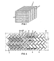
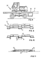
- the bricks 1 are handled by means of suction-pads 2 which are schematically represented in Figure 4, and are layered in transverse rows 3 in a supplied brick pack 4 as represented in Figure 1.
- the array of suction-pads 2 as illustrated in Figure 4 comprises multiple lazy-tongs 5 having spacers 6 in the form of spring means between the respective lazy-tongs 7 in order to obtain equal interspacing transversely.
- the bricks 1 in the brick pack 4 are spaced transversely at a pitch of B plus some clearance, but are spaced transversely at a pitch distance of (B+w)V2 before the bricks are turned 45°, whereby the desired joint width is thus taken into account.
- the suction-pads 2 with the bricks which are hatched in Figure 4 are first lowered to a separate level.
- the lazy-tongs legs 9 have been adjusted at 45°, the lowered suction-pads and bricks are raised again to the initial level, and all bricks will then accurately fit in the herringbone pattern.
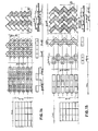
- FIG. 4 shows some bricks 1 cross hatched to more clearly bring out the alternating brick rows 3 in their herringbone pattern. Also only a few of a great number of spacing springs 6 which are connected to the centers of brick “squares" or bats are shown so as not to blur the view in Figure 4.
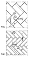
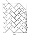
- Figure 5 fundamentally shows basic "squares" or bats forming rectangles which are at a pitch of (B+w)V2, and in Figure 5 some of said basic rectangles are filled with bricks leaving a clearance s or joint width w all about.
- the dashed lines indicate the bottoms of the brick nests in the support sheet 19.
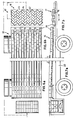
- Figures 6 and 7 show in plan view and in lateral view, respectively, a supply device 15, forming rows 16 of bricks 12 in spaced and staggered relationship, which rows 16 of bricks are laid in a herringbone arrangement, while performing a tongs motion such as by means of a lazy-tongs system as illustrated in Figure 4 or by means of chutes as described in the following in view of Figure 13, on a stacking device 17 laying the rows 16 of bricks every other high and low on for instance a lay mould 18, as can be seen in Figure 7, or on a similarly formed pallet 13 on which the rows 16 of bricks are packed in various layers.
- a supply device 15 forming rows 16 of bricks 12 in spaced and staggered relationship, which rows 16 of bricks are laid in a herringbone arrangement, while performing a tongs motion such as by means of a lazy-tongs system as illustrated in Figure 4 or by means of chutes as described in the following in view of Figure 13, on a stacking device 17 laying the rows 16 of bricks every other high
- Figure 8 is an illustration of a vehicle 22 equipped for packeting bricks in the proposed manner, and also comprising the supply device 15 and the stacking device 17.
- Figures 9 and 10 show schematic cross-sections according to the line IX-IX in Figure 5.
- pockets 20 adapted to receive the rows 16 of bricks, located every other high and low, are formed, which pockets are preferably formed homingly, with a lower size of the pocket 20 that corresponds with the size of the bricks, while the upper size of the pocket 20 is wider.
- the pockets 20 may be provided with semi-rigid somewhat deformable supporting edges 21 for the bricks 12, through which the bricks 12 can be pushed by exerting a force so as to lower these into the road surface.
- the rows 16 of bricks can also be placed in their herringbone pattern along chutes, as illustrated in Figure 13, but the use of tongs is presently preferred.
- the tongs may consist of two relatively slidable laying strips, as will be readily understood.
- the formed rows of bricks in a herringbone pattern are supplied each time every other high and low on the stacking device 17.
- the stacking device 17 can be arranged under the end of the supply device 15 for telescoping it in and out so as to transfer each subsequent row 16 of bricks from the supply device 15 to its destination on the stacking device which is correctly positioned therebelow.
- Figure 11 shows how the bricks are stacked at 23 in rows at three separate levels, by the use of multiple lazy-tongs (not shown), and are destacked at the output side 24 in a herringbone pattern in one plane, while an endless belt 25 is used, preferably a wafer belt with small slopes to retain the bricks in the desired relationship. It is remarked that each time the last laid lowermost rows of bricks will form the first rows of the next packet later on. In Figure 11 the pertaining rows of bricks are indicated by hatching.
- Figure 12 shows packet layers laid in the road surface by means of a high/low lay system such as illustrated in Figure 10, with the outermost rows of the packet layers that are laid, situated low and adjoining the outermost rows of bricks of the adjacent packet layers, which are also situated low.
- the chutes 25' as illustrated in Figure 13 act alternatingly high and low, passing one over another.
- tongs motion to be performed can be used as well, with tongs consisting of mutually slidable support rods in a parallel rod assembly.
- Figures 14 and 15 give a view of the sequence of steps when a number of rows are placed in their relationship at the same time and when the bricks, after turning with lazy-tongs, are shoved- on one row at a time, respectively.
- Figures 14 and 15 clearly show how support means are to be manipulated to transfer bricks from a brick pack as shown at the left into a herringbone pattern as shown at the right.
- spacer springs means can be spanned as straight guiding means between all the centerline-pivots of the lazy-tongs legs 9, which spring means are laterally seated on the lateral adjusting rules, and in so far as being compression springs, are each enclosed in a casing to avoid buckling, and furthermore, in order to avoid a dead-center position of the lazy-tongs, a lead i.e. a preliminary deflection in the deflecting direction can be given to the outermost lazy-tongs legs.
- the spaces of joints between the bricks can be suitably preformed by using a method comprising pre-milking the lateral surfaces of the bricks with binder milk i.e. thin jointing mortar milk or actually substantial mud or mud sludge of clay loam with an addition to increase the binding ability.
- binder milk i.e. thin jointing mortar milk or actually substantial mud or mud sludge of clay loam with an addition to increase the binding ability.
- the road surface panel as illustrated in Figure 16 is preformed by laying bricks 12 on a base layer 27 on which a binder milk bath of particularly clay or loam with, when necessary, an addition of a binding agent such as cement is formed, which clay binder also penetrates into the joints 28 between the bricks.
- a binder milk bath of particularly clay or loam with, when necessary, an addition of a binding agent such as cement is formed, which clay binder also penetrates into the joints 28 between the bricks.
- the bricks are now not laid one at a time in the small surface, destined forthat purpose, but for instance one hundred bricks are laid in the surface destined for that.
- This can be done within a suitable framing mould 29 which can be removed from the formed packet layer 26 upon hardening of the binder.
- This forming method is not only to be used for road surface panels but also for floor and wall panels in general.
- a lay system such as lazy-tongs table 10 as schematically indicated in Figure 4, the lay mould 18 as shown in Figure 7 or support
Landscapes
- Engineering & Computer Science (AREA)
- Architecture (AREA)
- Civil Engineering (AREA)
- Structural Engineering (AREA)
- Road Paving Structures (AREA)
- Devices For Post-Treatments, Processing, Supply, Discharge, And Other Processes (AREA)
- Road Repair (AREA)
- Processing Of Stones Or Stones Resemblance Materials (AREA)
- Road Paving Machines (AREA)
- Furnace Housings, Linings, Walls, And Ceilings (AREA)
Claims (9)
Priority Applications (1)
| Application Number | Priority Date | Filing Date | Title |
|---|---|---|---|
| AT85200670T ATE41797T1 (de) | 1984-05-08 | 1985-04-29 | Verfahren fuer das mechanische verlegen von pflastersteinen in einem fischgraetenmuster. |
Applications Claiming Priority (2)
| Application Number | Priority Date | Filing Date | Title |
|---|---|---|---|
| NL8401469A NL8401469A (nl) | 1984-05-08 | 1984-05-08 | Werkwijze voor het mechanisch leggen van stenen in keperverband, en een inrichting daarvoor. |
| NL8401469 | 1984-05-08 |
Publications (3)
| Publication Number | Publication Date |
|---|---|
| EP0164146A2 EP0164146A2 (de) | 1985-12-11 |
| EP0164146A3 EP0164146A3 (en) | 1986-02-26 |
| EP0164146B1 true EP0164146B1 (de) | 1989-03-29 |
Family
ID=19843921
Family Applications (1)
| Application Number | Title | Priority Date | Filing Date |
|---|---|---|---|
| EP85200670A Expired EP0164146B1 (de) | 1984-05-08 | 1985-04-29 | Verfahren für das mechanische Verlegen von Pflastersteinen in einem Fischgrätenmuster |
Country Status (5)
| Country | Link |
|---|---|
| US (1) | US4846601A (de) |
| EP (1) | EP0164146B1 (de) |
| AT (1) | ATE41797T1 (de) |
| DE (1) | DE3569138D1 (de) |
| NL (1) | NL8401469A (de) |
Families Citing this family (12)
| Publication number | Priority date | Publication date | Assignee | Title |
|---|---|---|---|---|
| NL189867C (nl) * | 1985-02-14 | 1996-05-24 | Stichting Octrooibeheer Polak | Verplaatsbare inrichting ten behoeve van het hergebruik van uit een bestaand wegdek opgenomen straatstenen. |
| NL193667C (nl) * | 1986-04-01 | 2000-06-06 | Luijten Arend | Werkwijze voor het mechanisch leggen van stenen in keperverband. |
| GB2192417A (en) * | 1986-07-09 | 1988-01-13 | Colin Golby Tustian | Mechanised paving block laying system |
| NL8602475A (nl) * | 1986-10-01 | 1988-05-02 | Stramech Bv | Werkwijze en inrichting voor het leggen van een wegdek benevens een heftoestel ten gebruike daarbij. |
| US6067765A (en) * | 1997-02-21 | 2000-05-30 | Msx, Inc. | Insulated layer of concrete |
| NL1009689C2 (nl) * | 1998-07-17 | 2000-01-18 | Theodorus Johannes Adrianus Br | Inrichting voor het verplaatsen van stenen. |
| US6551016B2 (en) * | 2001-03-27 | 2003-04-22 | John Kevin Guidon | Paver Guid-on system |
| NL1026269C2 (nl) | 2004-05-26 | 2005-11-30 | Arend Luijten | Werkwijze en inrichting voor het maken van een keperverband van stenen. |
| US7425106B2 (en) * | 2004-09-13 | 2008-09-16 | Anchor Wall Systems, Inc. | Concrete pavers positioned in a herringbone pattern |
| NL2001093C2 (nl) | 2007-12-14 | 2009-06-16 | Crh Kleiwaren Beheer B V | Bestratingsmachine. |
| USD721774S1 (en) * | 2012-09-14 | 2015-01-27 | New Jersey Basketball LLC | Basketball court |
| NL1044537B1 (nl) * | 2023-01-31 | 2024-08-22 | Petrus Maria Van Kuijk Hendricus | Bestratingsmachine |
Family Cites Families (13)
| Publication number | Priority date | Publication date | Assignee | Title |
|---|---|---|---|---|
| US132560A (en) * | 1872-10-29 | Improvement in forms for laying brick pavements | ||
| US512579A (en) * | 1894-01-09 | Martin | ||
| US1825320A (en) * | 1927-05-27 | 1931-09-29 | Kuerts Ernst | Block paving machine and the like |
| AT164083B (de) * | 1946-05-18 | 1949-09-26 | Franz Quidenus | Anlage für grobkeramische Massenerzeugnisse, insbesondere Ziegelei |
| US3392851A (en) * | 1965-03-22 | 1968-07-16 | Pearne And Lacy Machine Compan | Brick stacker |
| US3427936A (en) * | 1966-08-01 | 1969-02-18 | Meij Antonius J Van Der | Method for paving a street |
| NL7104261A (de) * | 1971-03-31 | 1972-10-03 | ||
| DE2254432C2 (de) * | 1972-11-07 | 1974-03-07 | C. Keller & Co, 4533 Laggenbeck | Greifer für das mechanische Umsetzen von in geradzahligen Setzlagenreihen liegenden Ziegelformlingen zu Stapeln im Schräg-Kreuz-Verband |
| FR2413958A1 (fr) * | 1978-01-06 | 1979-08-03 | Thieffry Luc | Procede et installation pour le moulage et la pose mecanique ou semi-mecanique de paves ou dalles modules, en beton ou autre materiau |
| SE8103903L (sv) * | 1981-06-22 | 1982-12-23 | Medline Ab | Anordning for tillslutning av kroppskanaler |
| NL8201109A (nl) * | 1982-03-17 | 1983-10-17 | Verheijen Maschf Bv | Werkwijze en inrichting voor het mechanisch leggen van een bestrating. |
| US4495132A (en) * | 1982-09-23 | 1985-01-22 | Texas Industries, Inc. | Method and apparatus for making antique brick |
| US4685714A (en) * | 1986-12-18 | 1987-08-11 | Hoke Thomas A | Lifting assembly |
-
1984
- 1984-05-08 NL NL8401469A patent/NL8401469A/nl not_active Application Discontinuation
-
1985
- 1985-04-29 DE DE8585200670T patent/DE3569138D1/de not_active Expired
- 1985-04-29 EP EP85200670A patent/EP0164146B1/de not_active Expired
- 1985-04-29 AT AT85200670T patent/ATE41797T1/de active
-
1987
- 1987-07-13 US US07/073,409 patent/US4846601A/en not_active Expired - Fee Related
Also Published As
| Publication number | Publication date |
|---|---|
| US4846601A (en) | 1989-07-11 |
| EP0164146A3 (en) | 1986-02-26 |
| ATE41797T1 (de) | 1989-04-15 |
| DE3569138D1 (en) | 1989-05-03 |
| NL8401469A (nl) | 1985-12-02 |
| EP0164146A2 (de) | 1985-12-11 |
Similar Documents
| Publication | Publication Date | Title |
|---|---|---|
| EP0164146B1 (de) | Verfahren für das mechanische Verlegen von Pflastersteinen in einem Fischgrätenmuster | |
| US5802792A (en) | Drywall construction and means therefor | |
| US4147491A (en) | Apparatus for forming simulated old brick | |
| CN105383936A (zh) | 一种智能分区码垛编排方法与装置 | |
| CN112124686A (zh) | 一种砖块的自动打包系统及其打包方法 | |
| BG100294A (bg) | Метод за изработване на панел и съоръжение за осъществяването му | |
| GB2091775A (en) | Building block | |
| US5358031A (en) | Interlocking checker bricks and method and apparatus for making | |
| DE3927251A1 (de) | Verfahren und vorrichtung zum legen von eisenbahnschienen | |
| EP0102999B1 (de) | Verfahren und einrichtung für das maschinelle verlegen von pflastersteinen | |
| SK19995A3 (en) | Method and device for mutual putting off of rows of rectangle plastic air-entrained concrete bodies | |
| DE2508795A1 (de) | Verfahren und vorrichtung zur herstellung von isolierbausteinen | |
| JP2020084495A (ja) | 固定具 | |
| EP1604923A1 (de) | Einrichtung und Verfahren zum Stapeln und Transportieren von Platten | |
| CN207791280U (zh) | 一种标砖无托盘全自动包装系统 | |
| FR2506276B3 (de) | ||
| US4061528A (en) | Apparatus for the manufacture of prefabricated lined wall sections | |
| CN212196094U (zh) | 一种砌块定量稳定输送装置 | |
| EP0004207A1 (de) | Vorrichtung und Methode zum Stapeln von rechteckigen Gegenständen | |
| ES2016250B3 (es) | Metodo y montaje para producir elementos tapiados para levantar paredes. | |
| JPS6313332Y2 (de) | ||
| JP2003028345A (ja) | 地中埋設管路及びそれに用いる管枕 | |
| JP6899157B2 (ja) | 構造物の構築方法 | |
| US3881981A (en) | Device and method for prefabricating wall panels from block-like articles | |
| CN211894363U (zh) | 一种装配式建筑墙体运输保护装置 |
Legal Events
| Date | Code | Title | Description |
|---|---|---|---|
| PUAI | Public reference made under article 153(3) epc to a published international application that has entered the european phase |
Free format text: ORIGINAL CODE: 0009012 |
|
| AK | Designated contracting states |
Designated state(s): AT BE CH DE FR GB IT LI LU NL SE |
|
| PUAL | Search report despatched |
Free format text: ORIGINAL CODE: 0009013 |
|
| AK | Designated contracting states |
Designated state(s): AT BE CH DE FR GB IT LI LU NL SE |
|
| 17P | Request for examination filed |
Effective date: 19860716 |
|
| RAP1 | Party data changed (applicant data changed or rights of an application transferred) |
Owner name: LUYTEN HOLDING B.V. |
|
| RIN1 | Information on inventor provided before grant (corrected) |
Inventor name: LUIJTEN, AREND |
|
| 17Q | First examination report despatched |
Effective date: 19870626 |
|
| GRAA | (expected) grant |
Free format text: ORIGINAL CODE: 0009210 |
|
| AK | Designated contracting states |
Kind code of ref document: B1 Designated state(s): AT BE CH DE FR GB IT LI LU NL SE |
|
| PG25 | Lapsed in a contracting state [announced via postgrant information from national office to epo] |
Ref country code: SE Effective date: 19890329 Ref country code: LI Effective date: 19890329 Ref country code: IT Free format text: LAPSE BECAUSE OF FAILURE TO SUBMIT A TRANSLATION OF THE DESCRIPTION OR TO PAY THE FEE WITHIN THE PRESCRIBED TIME-LIMIT;WARNING: LAPSES OF ITALIAN PATENTS WITH EFFECTIVE DATE BEFORE 2007 MAY HAVE OCCURRED AT ANY TIME BEFORE 2007. THE CORRECT EFFECTIVE DATE MAY BE DIFFERENT FROM THE ONE RECORDED. Effective date: 19890329 Ref country code: FR Free format text: THE PATENT HAS BEEN ANNULLED BY A DECISION OF A NATIONAL AUTHORITY Effective date: 19890329 Ref country code: CH Effective date: 19890329 Ref country code: BE Effective date: 19890329 Ref country code: AT Effective date: 19890329 |
|
| REF | Corresponds to: |
Ref document number: 41797 Country of ref document: AT Date of ref document: 19890415 Kind code of ref document: T |
|
| PG25 | Lapsed in a contracting state [announced via postgrant information from national office to epo] |
Ref country code: LU Free format text: LAPSE BECAUSE OF NON-PAYMENT OF DUE FEES Effective date: 19890430 |
|
| REF | Corresponds to: |
Ref document number: 3569138 Country of ref document: DE Date of ref document: 19890503 |
|
| PG25 | Lapsed in a contracting state [announced via postgrant information from national office to epo] |
Ref country code: GB Effective date: 19890529 |
|
| REG | Reference to a national code |
Ref country code: CH Ref legal event code: PL |
|
| EN | Fr: translation not filed | ||
| PG25 | Lapsed in a contracting state [announced via postgrant information from national office to epo] |
Ref country code: DE Effective date: 19900103 |
|
| GBPC | Gb: european patent ceased through non-payment of renewal fee | ||
| PLBE | No opposition filed within time limit |
Free format text: ORIGINAL CODE: 0009261 |
|
| STAA | Information on the status of an ep patent application or granted ep patent |
Free format text: STATUS: NO OPPOSITION FILED WITHIN TIME LIMIT |
|
| 26N | No opposition filed | ||
| NLS | Nl: assignments of ep-patents |
Owner name: AREND LUIJTEN TE SPIJKENISSE. |
|
| PGFP | Annual fee paid to national office [announced via postgrant information from national office to epo] |
Ref country code: NL Payment date: 19970430 Year of fee payment: 13 |
|
| PG25 | Lapsed in a contracting state [announced via postgrant information from national office to epo] |
Ref country code: NL Free format text: LAPSE BECAUSE OF NON-PAYMENT OF DUE FEES Effective date: 19981101 |
|
| NLV4 | Nl: lapsed or anulled due to non-payment of the annual fee |
Effective date: 19981101 |