EP0163298B1 - Pcm coder/decoder with two-wire/four-wire conversion - Google Patents
Pcm coder/decoder with two-wire/four-wire conversion Download PDFInfo
- Publication number
- EP0163298B1 EP0163298B1 EP85106606A EP85106606A EP0163298B1 EP 0163298 B1 EP0163298 B1 EP 0163298B1 EP 85106606 A EP85106606 A EP 85106606A EP 85106606 A EP85106606 A EP 85106606A EP 0163298 B1 EP0163298 B1 EP 0163298B1
- Authority
- EP
- European Patent Office
- Prior art keywords
- circuit
- signal
- output
- pcm
- digital filter
- Prior art date
- Legal status (The legal status is an assumption and is not a legal conclusion. Google has not performed a legal analysis and makes no representation as to the accuracy of the status listed.)
- Expired
Links
Images


Classifications
-
- H—ELECTRICITY
- H04—ELECTRIC COMMUNICATION TECHNIQUE
- H04B—TRANSMISSION
- H04B3/00—Line transmission systems
- H04B3/02—Details
- H04B3/20—Reducing echo effects or singing; Opening or closing transmitting path; Conditioning for transmission in one direction or the other
- H04B3/23—Reducing echo effects or singing; Opening or closing transmitting path; Conditioning for transmission in one direction or the other using a replica of transmitted signal in the time domain, e.g. echo cancellers
-
- H—ELECTRICITY
- H04—ELECTRIC COMMUNICATION TECHNIQUE
- H04B—TRANSMISSION
- H04B1/00—Details of transmission systems, not covered by a single one of groups H04B3/00 - H04B13/00; Details of transmission systems not characterised by the medium used for transmission
- H04B1/38—Transceivers, i.e. devices in which transmitter and receiver form a structural unit and in which at least one part is used for functions of transmitting and receiving
- H04B1/40—Circuits
- H04B1/54—Circuits using the same frequency for two directions of communication
- H04B1/58—Hybrid arrangements, i.e. arrangements for transition from single-path two-direction transmission to single-direction transmission on each of two paths or vice versa
- H04B1/586—Hybrid arrangements, i.e. arrangements for transition from single-path two-direction transmission to single-direction transmission on each of two paths or vice versa using an electronic circuit
Definitions
- the present invention relates to a PCM coder and decoder having the function of two-wire/four-wire conversion, and more particularly to a coder and decoder (CODEC) which is used in the subscriber's circuit of a digital switching system, etc. and in which a PCM signal applied to a four-wire receiving line is decoded and converted into an analogue signal that is sent to a two-wire line being subscriber's line, while an analogue signal from the two-wire subscriber's line is coded into a PCM signal that is sent to a four-wire transmission line.
- CDM coder and decoder which is used in the subscriber's circuit of a digital switching system, etc.
- CDM signal applied to a four-wire receiving line is decoded and converted into an analogue signal that is sent to a two-wire line being subscriber's line
- an analogue signal from the two-wire subscriber's line is coded into a PCM signal that is sent to a four-wire
- the subscriber's circuit of a switchboard is arranged so as to have the functions of battery feed, overvoltage protection, ringing, supervision, PCM coding and decoding, two-wire/four-wire conversion, test, etc.
- a circuit for canceling a return signal namely, a balancing circuit is constructed of a digital circuit unitarily with the PCM coder and decoder. More specifically, a voice analogue signal from a two-wire line to be transmitted is converted into a digital signal via a pre-filter for eliminating high frequency noise and an A/D converter, and the digital signal has its band limited by a digital filter and is thereafter delivered to a transmission line as a PCM signal.
- a PCM signal received from a receiving line has its band limited by a digital filter and is passed through a D/A converter and a post-filter so as to be supplied to a two-wire line as a voice analogue signal.
- the balancing circuit is so constructed that a filter which has characteristics approximating the transmission characteristics of the path of the return signal is interposed between the A/D converter and the D/A converter so as to subtract the output of the filter from the output of the A/D converter.
- an amplifier circuit is generally provided in the path of the return signal. It is therefore sometimes the case that the leakage signal becomes greater in amplitude than the received signal and exceeds the coding level of the A/D converter. Even when the leakage signal is not higher than the maximum coding level, the return signal is superposed on the signal from the two-wire line which ought to be transmitted, resulting in the problem that the dynamic range of the transmission signal becomes insufficient, which deteriorate the S/N ratio.
- the composite amplitude of the return signal and the transmission signal might exceed a supply voltage to destroy the LSI.
- a balancing circuit is constructed of only analogue circuits and is formed between the input of an A/D converter and the output of a D/A converter. Since, however, the balancing circuit needs to be suited to various loads, namely, impedances on the two-wire line side, it must comprise a plurality of analogue circuits having different transfer functions, and a circuit for selecting and controlling the optimum analog circuit is required.
- a plurality of balancing circuits can be readily realized by changing the coefficient of a multiplier unit and without adding any circuit device, whereas in case of analogue circuitry, the realization of a plurality of balancing circuits of different transfer functions makes it necessary to switch and use different resistors, capacitors, operational amplifiers etc., resulting in a large circuit device scale which incurs the problem that an economical occupation area cannot be held in the LSI implementation.
- a circuit arrangement according to the first part of claim 1 and comprising an analogue balancing circuit and a digital balancing circuit is known from "The Bell System Technical Journal", Vol. 60, No. 7, pp. 1585 - 1619, September 1981.
- the analogue balancing circuit requires a especial transfer function having one pole and a frequency characteristic with its zero point fixed so that the impedance of a two-wire/four-wire interface portion (for example, a transformer) and a plurality of two-wire subscriber's line impedances can be coped with.
- an analogue balancing circuit requires a capacitor or an inductor of comparatively large element value, and the LSI implementation is, in effect, impossible from the economical viewpoint as in the foregoing case.
- a fluctuation in the absolute value of the element value directly changes the frequency - gain characteristic and phase characteristic of a return signal, and it becomes very difficult to suppress the return signal precisely by means of the digital balancing circuit at the succeeding stage.
- PCM coder/decoder is known from "Electronics Engineering", Vol. 55, No. 684, pp. 37 - 43, December 1983, in which a compression of the PCM signal is performed by a signal processor connected to the outgoing transmission line.
- the balancing circuit is divided into two portions, the first portion forming a digital circuit interposed between the input side of a D/A converter and the output side of an A/D converter and the second portion forming an analogue circuit interposed between the output side of the D/A converter and the input side of the A/D converter and having no frequency response, namely, having a gain independent of frequencies.
- the analogue circuit is used for stably lowering the level of the return signal, whereby degradation in the S/N ratio of the A/D converter is lessened, and the digital circuit is used for changing the transfer function of a digital filter in accordance with the impedance of a two-wire transmission line side, whereby the return signal can be canceled at high precision.
- a circuit portion whose sampling frequency is high, that is, whose sampling period is short is used for adjusting a signal delay, whereby a delay compensation of high precision is permitted, and a sufficient return loss is attained.
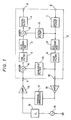
- Fig. 1 is a diagram showing the arrangement of an embodiment of a PCM CODEC according to the present invention.
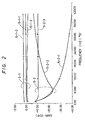
- Fig. 2 shows a frequency characteristic diagram of the transfer functions of return signals.
- Figs. 3 and 4 are circuit diagrams each showing an embodiment of an analogue balancing circuit in Fig. 1.
- Fig. 5 shows the arrangement of another embodiment of the CODEC according to the present invention.
- Fig. 1 is a diagram showing the arrangement of one embodiment of a PCM coder and decoder (CODEC) according to the present invention.
- a portion enclosed with a dotted line 0 is a coding and decoding portion which has a balancing circuit, while the other portion is an equivalent circuit from the analogue input and output terminals 1, 10 of this coder and decoder to a telephone set and is conjointly illustrated for the description of the present invention.
- a PCM signal from a receiving line (not shown) which is a four-wire line is applied through a terminal 6 and has its band limited by a digital filter 7.
- Part of the resulting signal is converted by a D/A converter 8 into an analogue signal, which is smoothed by a post-filter 9 and then provided from the terminal 10 as a decoded voice analogue signal.
- a voice analogue signal to be transmitted is applied through the input terminal 1, an adder 14 and a pre-filter for eliminating high frequency noise 2 to an A/D converter 3, by which it is converted into a digital signal.
- the digital signal is passed via an adder 12 and has its band limited by a digital filter 4, whereupon the resulting signal is delivered from an output terminal 5 to a transmission line (not shown) of a four-wire line as a PCM signal.
- a digital filter 11 and an analogue filter 13 constitute the balancing circuit along with the adder 12 and the adder 14 respectively.
- This balancing circuit is a circuit for eliminating a signal, which arises in such a manner that the analogue signal from the terminal 10 returns through an amplifier 16, a terminal impedance 17 and an amplifier 16, and it forms the essential portion of the present invention.
- the reception side voice analogue signal at the terminal 10 After passing through the external amplifier 16 (gain b ), the reception side voice analogue signal at the terminal 10 has its voltage divided by the terminal circuit (impedance Z T ) 17, and the resulting signal is supplied to a two-wire side telephone line (impedance Z L ) 18.
- the transmission side voice analogue signal is passed from a signal source 19 through the impedance 18 and is divided by the terminal impedance 17, and the resulting signal is supplied to the input terminal 1 of the coder and decoder through the external amplifier 15 (gain a ).
- part of the reception side analogue signal returns to the transmission side. Therefore, letting v s and v r denote the signal voltages of the signal source 19 and the terminal 10 respectively, a voltage v1 at the terminal 1 becomes a value expressed by the following equation:
- the component of the return signal is the second term.
- s in the above equation is a symbol indicative of a complex angular frequency.
- the terminal impedance Z T is selected to be equal to Z LO
- Fig. 3 shows a circuit illustrative of one embodiment of the balancing circuit 13 and adder 14 in Fig. 1 in the case of ab > O.
- a terminal 4-8 is connected to the input terminal 1
- a terminal 4-9 is connected to the output side of the post-filter
- a terminal 4-14 is connected to the input side of the pre-filter.
- a capacitor 4-6 (capacitance C4), a capacitor 4-7 (capacitance C5) and an operational amplifier 4-2 constitute a well-known amplifier
- a capacitor 4-3 (capacitance C1), a capacitor 4-4 (capacitance C2), a capacitor 4-5 (capacitance C3) and an operational amplifier 4-1 constitute a circuit for the addition between the input voltage of the terminal 4-8 and the output voltage of the amplifier 4-2.
- a capacitor 4-11 (capacitance C6), a capacitor 4-12 (capacitance C7) and an operational amplifier 4-13 constitute an inverting amplifier 4-0 for the output voltage of the amplifier 4-1.
- Fig. 4 shows one embodiment of the balancing circuit 13 and adder 14 in Fig. 1 in the case of ab ⁇ 0. Since, in this case, the phase of the return signal at the terminal 4-8 has been inverted, the signal for cancellation to be applied from the terminal 4-9 need not be phase-inverted. It is accordingly possible to omit the capacitors 4-6 and 4-7 and the amplifier 4-2 and to apply the output signal of the post-filter directly from the capacitor 4-4. The operation of this embodiment can be readily conjectured from the above first embodiment, and shall not be explained.
- the inverting amplifier 4-0 indicated by a broken line can be dispensed with in such a way that the output voltage 4-10 of the amplifier 4-1 is used as an input signal to the pre-filter.
- the phase of the adder output signal responsive to the input signal from the terminal 4-8 is inverted.
- the phase inversion of the signal may be performed in any desired place of the pre-filter, the A/D converter, the digital filter, etc., and the phase inversion is possible by the use of a method already known extensively and generally.
- the capacitance ratios (namely, the values of k ) can be switched in fixed or automatic selection fashion in correspondence with the gain (ab) of the external circuit or the impedance Z Li of the two-wire line.
- the potential of the inverting input terminal of the operational amplifier 4-1 is fixed to the potential of the non-inverting input terminal (earth), and hence, the allowable voltage of the signal to be applied to the input terminal 4-8 (1 in Fig. 1) is determined by the breakdown voltage of the capacitor 4-3.
- the allowable voltage is not affected by a supply voltage or the breakdown voltage of any other circuit element (for example, the operational amplifier 4-1).
- the capacitors may well be replaced with resistance elements.
- the desired value k can be exactly actualized with a comparatively small area within the LSI.
- the return signal can be stably attenuated by the use of the circuit of the present invention though insufficiently, the remaining return signals can be eliminated by the balancing circuit which is composed of the digital filter 11 and the adder 12. More specifically, the transfer functions of Eq. (7) are prepared by the digital filter 11 and are subtracted by the adder 12, whereby the remaining return components can be eliminated. Since the arrangement of the digital filter has hitherto been well known, the detailed explanation shall be omitted.
- the digital filter can approximate Eq. (7) with transfer functions of the second order, third order or so, and it can be adapted to the change of the line impedance Z L of the two-wire side line by changing coefficients within the filter responsively and can eliminate the return components at high precision.
- Fig. 5 is a diagram which shows the arrangement of another embodiment of the PCM coder and decoder according to the present invention.
- the same constituents as in Fig. 1 are indicated by identical symbols.
- the present embodiment is so arranged that delays which arise when return signals pass through digital filters 4-P and 7-S, an A/D converter 3, a D/A converter 8, analogue filters 2 and 9, etc. are precisely compensated by the output of a digital filter 11.
- a PCM signal (a PCM signal according to the ⁇ -law) from a four-wire receiving line 6-B is converted by an expandor 22 into a linear PCM signal, which is converted by a digital filter 7-P into a digital signal having a sampling frequency of 32 kHz. Part of the digital signal is further changed by the digital filter 7-S into a digital signal having a sampling frequency of 512 kHz, and the resulting signal is passed through delay means 23. The delayed signal is passed through the over-sampling type D/A converter 8 and the post-filter 9 to become a decoded analogue signal, which is partly delivered to a two-wire line being subscriber's line via a buffer amplifier 16 and a terminal impedance 17.
- an analogue signal 19 from the subscriber's line is passed through an amplifier 15 and the pre-filter 2 and is converted by the over-sampling type A/D converter 3 into a digital signal sampled at a sampling frequency of 512 kHz.
- the digital signal is further changed into a digital signal at a sampling frequency of 32 kHz by the digital filter 4-P, and the resulting signal is applied to an adder 12.
- the adder 12 serves to eliminate a component which is such that the digital signal from the four-wire receiving line 6-B has been decoded and returned to the path of the blocks 2, 3 and 4-P through the amplifier 16 as well as the terminal impedance 17.
- Part of the output of the digital filter 7-P is applied to the adder 12 through delay means 24 as well as the BN (balancing network) filter 11.
- the output of the adder 12 applies only the signal component from the signal source 19 to a digital filter 4-S, which converts the applied signal into a linear PCM signal (at a sampling frequency of 8 kHz). Further, the linear PCM signal is changed into a nonlinear PCM signal of, for example, the ⁇ -law or the A-law by a compressor 21, and the nonlinear PCM signal is delivered to a four-wire transmission line 5-B.
- T d t1 + t4 + t ad + t da
- t1, t4, t ad and t da denote the delay times of the filters 4-P, 7-S, the A/D converter 3 and the D/A converter 8, respectively.
- a sampling frequency of at least 512 kHz is employed for the over-sampling type A/D converter 2 and D/A converter 8, and a clock at a still higher frequency (for example, 1024 kHz) is employed for the digital filter 4-P for processing the A/D conversion result. Accordingly, when this clock is used, the delay adjustments in the delay circuits 23 and 24 can be performed at a precision corresponding to one clock pulse period of 1 ⁇ s or less.
- the delays of the filters 4-P and 7-S, the A/D and D/A converters 3 and 8, the pre- and post-filters 2 and 9, etc. are considered, and the delay magnitude of the delay circuit 23 is adjusted so that the sum between the total of the considered delay magnitudes and the delay magnitude of the delay circuit 23 may become close to a value which is integral times the sampling period of the filter 7-P. Then, the delay of a signal (the output of the filter 11) for canceling the return signal can be adjusted by the simple delay circuit 24.
- the delay circuit 23 can be controlled with the clock of 4.096 MHz, and the delay magnitude thereof can therefore be set at 5.62 ⁇ s (23 x 1/4.096 x 106). Accordingly, the total delay magnitude can be set at 125.1 ⁇ s by the insertion of the delay circuit 23.
- the delay circuit in Fig. 5 can be readily constructed by the use of a shift register, a memory or the like. While, in the embodiment, the delay circuit 23 is inserted on the input side of the D/A converter, it may well be installed on the input side of the filter 7-S, the output side of the A/D converter or the output side of the filter 4-P, or it may well be installed in dispersed fashion.
- the compensation of a signal delay is permitted at high precision, and a two-wire/four-wire conversion function of good characteristics can be constructed and realized within a digital CODEC LSI, so that the miniaturization and economization of the subscriber's circuit of a switching system becomes possible over the function in the prior art constructed by adding a transformer or an external circuit.
Description
- The present invention relates to a PCM coder and decoder having the function of two-wire/four-wire conversion, and more particularly to a coder and decoder (CODEC) which is used in the subscriber's circuit of a digital switching system, etc. and in which a PCM signal applied to a four-wire receiving line is decoded and converted into an analogue signal that is sent to a two-wire line being subscriber's line, while an analogue signal from the two-wire subscriber's line is coded into a PCM signal that is sent to a four-wire transmission line.
- The subscriber's circuit of a switchboard is arranged so as to have the functions of battery feed, overvoltage protection, ringing, supervision, PCM coding and decoding, two-wire/four-wire conversion, test, etc.
- In the arrangement having these functions, a circuit for the two-wire/four-wire conversion has heretofore been constructed separately from a PCM coder and decoder. Recently, however, with the progresses of semiconductor integration technology and signal processing circuit technology, it is studied to construct the conversion circuit unitarily with the PCM coder and decoder (Electronics/May 5, 1982, pp. 113 - 118). In order to realize the function of two-wire/four-wire conversion by the use of an electronic circuit, an input signal from a receiving line must be sent to only a bidirectional two-wire line, such as subscriber's line, so as not to return to a transmission line and then be provided as an output. To this end, in a PCM coder and decoder hitherto proposed, a circuit for canceling a return signal, namely, a balancing circuit is constructed of a digital circuit unitarily with the PCM coder and decoder. More specifically, a voice analogue signal from a two-wire line to be transmitted is converted into a digital signal via a pre-filter for eliminating high frequency noise and an A/D converter, and the digital signal has its band limited by a digital filter and is thereafter delivered to a transmission line as a PCM signal. On the other hand, a PCM signal received from a receiving line has its band limited by a digital filter and is passed through a D/A converter and a post-filter so as to be supplied to a two-wire line as a voice analogue signal. The balancing circuit is so constructed that a filter which has characteristics approximating the transmission characteristics of the path of the return signal is interposed between the A/D converter and the D/A converter so as to subtract the output of the filter from the output of the A/D converter.
- With the PCM coder and decoder as stated above, an amplifier circuit is generally provided in the path of the return signal. It is therefore sometimes the case that the leakage signal becomes greater in amplitude than the received signal and exceeds the coding level of the A/D converter. Even when the leakage signal is not higher than the maximum coding level, the return signal is superposed on the signal from the two-wire line which ought to be transmitted, resulting in the problem that the dynamic range of the transmission signal becomes insufficient, which deteriorate the S/N ratio.
- Further, when it is intended to implement the coder and decoder in the form of an LSI, the composite amplitude of the return signal and the transmission signal might exceed a supply voltage to destroy the LSI.
- In contrast to the aforementioned balancing circuit realized by the all-digital circuit, it is also considered that a balancing circuit is constructed of only analogue circuits and is formed between the input of an A/D converter and the output of a D/A converter. Since, however, the balancing circuit needs to be suited to various loads, namely, impedances on the two-wire line side, it must comprise a plurality of analogue circuits having different transfer functions, and a circuit for selecting and controlling the optimum analog circuit is required. In case of digital circuitry, a plurality of balancing circuits can be readily realized by changing the coefficient of a multiplier unit and without adding any circuit device, whereas in case of analogue circuitry, the realization of a plurality of balancing circuits of different transfer functions makes it necessary to switch and use different resistors, capacitors, operational amplifiers etc., resulting in a large circuit device scale which incurs the problem that an economical occupation area cannot be held in the LSI implementation.
- Further, a circuit arrangement according to the first part of claim 1 and comprising an analogue balancing circuit and a digital balancing circuit is known from "The Bell System Technical Journal", Vol. 60, No. 7, pp. 1585 - 1619, September 1981. The analogue balancing circuit, however, requires a especial transfer function having one pole and a frequency characteristic with its zero point fixed so that the impedance of a two-wire/four-wire interface portion (for example, a transformer) and a plurality of two-wire subscriber's line impedances can be coped with. Accordingly, the realization of such an analogue balancing circuit requires a capacitor or an inductor of comparatively large element value, and the LSI implementation is, in effect, impossible from the economical viewpoint as in the foregoing case. Moreover, with the analogue balancing circuit, a fluctuation in the absolute value of the element value directly changes the frequency - gain characteristic and phase characteristic of a return signal, and it becomes very difficult to suppress the return signal precisely by means of the digital balancing circuit at the succeeding stage.
- A further PCM coder/decoder is known from "Electronics Engineering", Vol. 55, No. 684, pp. 37 - 43, December 1983, in which a compression of the PCM signal is performed by a signal processor connected to the outgoing transmission line.
- It is an object of the present invention to provide a PCM coder and encoder having a balancing circuit which efficiently suppresses the return signal with a circuit arrangement that permits full LSI implementation.
- This object is met by the PCM coder and decoder defined in claim 1.
- According to the invention, the balancing circuit is divided into two portions, the first portion forming a digital circuit interposed between the input side of a D/A converter and the output side of an A/D converter and the second portion forming an analogue circuit interposed between the output side of the D/A converter and the input side of the A/D converter and having no frequency response, namely, having a gain independent of frequencies. The analogue circuit is used for stably lowering the level of the return signal, whereby degradation in the S/N ratio of the A/D converter is lessened, and the digital circuit is used for changing the transfer function of a digital filter in accordance with the impedance of a two-wire transmission line side, whereby the return signal can be canceled at high precision.
- In a more preferable aspect of performance of the present invention, a circuit portion whose sampling frequency is high, that is, whose sampling period is short is used for adjusting a signal delay, whereby a delay compensation of high precision is permitted, and a sufficient return loss is attained.
- The above-mentioned and other objects and features of the present invention will become more apparent from the following description taken in conjunction with the accompanying drawings.
- Fig. 1 is a diagram showing the arrangement of an embodiment of a PCM CODEC according to the present invention.
- Fig. 2 shows a frequency characteristic diagram of the transfer functions of return signals.
- Figs. 3 and 4 are circuit diagrams each showing an embodiment of an analogue balancing circuit in Fig. 1.
- Fig. 5 shows the arrangement of another embodiment of the CODEC according to the present invention.
- Fig. 1 is a diagram showing the arrangement of one embodiment of a PCM coder and decoder (CODEC) according to the present invention. In the figure, a portion enclosed with a dotted line 0 is a coding and decoding portion which has a balancing circuit, while the other portion is an equivalent circuit from the analogue input and
output terminals 1, 10 of this coder and decoder to a telephone set and is conjointly illustrated for the description of the present invention. A PCM signal from a receiving line (not shown) which is a four-wire line is applied through aterminal 6 and has its band limited by adigital filter 7. Part of the resulting signal is converted by a D/A converter 8 into an analogue signal, which is smoothed by a post-filter 9 and then provided from theterminal 10 as a decoded voice analogue signal. On the other hand, a voice analogue signal to be transmitted is applied through the input terminal 1, anadder 14 and a pre-filter for eliminatinghigh frequency noise 2 to an A/D converter 3, by which it is converted into a digital signal. Further, the digital signal is passed via anadder 12 and has its band limited by adigital filter 4, whereupon the resulting signal is delivered from anoutput terminal 5 to a transmission line (not shown) of a four-wire line as a PCM signal. - As will be discussed in detail later, a
digital filter 11 and ananalogue filter 13 constitute the balancing circuit along with theadder 12 and theadder 14 respectively. This balancing circuit is a circuit for eliminating a signal, which arises in such a manner that the analogue signal from theterminal 10 returns through anamplifier 16, aterminal impedance 17 and anamplifier 16, and it forms the essential portion of the present invention. - After passing through the external amplifier 16 (gain b), the reception side voice analogue signal at the
terminal 10 has its voltage divided by the terminal circuit (impedance ZT) 17, and the resulting signal is supplied to a two-wire side telephone line (impedance ZL) 18. On the other hand, the transmission side voice analogue signal is passed from asignal source 19 through theimpedance 18 and is divided by theterminal impedance 17, and the resulting signal is supplied to the input terminal 1 of the coder and decoder through the external amplifier 15 (gain a). At this time, part of the reception side analogue signal returns to the transmission side. Therefore, letting vs and vr denote the signal voltages of thesignal source 19 and theterminal 10 respectively, a voltage v₁ at the terminal 1 becomes a value expressed by the following equation:
- In the above equation, the component of the return signal is the second term. Here, by way of example, the following four typical impedances corresponding to a two-wire side telephone line in North America will be concretely studied:

s in the above equation is a symbol indicative of a complex angular frequency. The terminal impedance ZT is selected to be equal to ZLO, and the transfer function HBNO of thefirst balancing circuit 13 is assumed to be HBNO = k (real number). In this case, the transfer functions of the respective return signals at the terminal 1 for ZL = ZLi (i = 0, 1, 2, 3) become:
and the transfer functions Hli of the return signals at the output of theadder 14 become:
Accordingly, if
can be put, Hli = O can be established, and the return signals behind the output of theadder 14 can be completely canceled. Among the factors, the values of the gains a and b are uniquely determined by the level conditions of the switching system, but ZLi has various frequency characteristics as in Eqs. (2) - (5) mentioned before, so that the perfect cancellation is impossible. However, assuming k = 1 for ab = 2 by way of example, at least the return signal of ZLi = ZLO can be perfectly canceled, and besides, tile return signal levels can be effectively attenuated for the other impedances. Fig. 2 shows the comparison results of characteristics 5-1-i for HOi and characteristics 5-2-i for Hli (where i = 1, 2, 3) as evaluated under the aforementioned condition. For all ZLi (i = 1, 2, 3), there is the effect of the return signal suppression of at least 6 dB at the worst point of 3.4 kHz, and the dynamic range of the transmission signal can be expanded to that extent, so the S/N ratio can be improved. - Fig. 3 shows a circuit illustrative of one embodiment of the
balancing circuit 13 andadder 14 in Fig. 1 in the case of ab > O. A terminal 4-8 is connected to the input terminal 1, a terminal 4-9 is connected to the output side of the post-filter, and a terminal 4-14 is connected to the input side of the pre-filter. A capacitor 4-6 (capacitance C₄), a capacitor 4-7 (capacitance C₅) and an operational amplifier 4-2 constitute a well-known amplifier
Likewise, a capacitor 4-3 (capacitance C₁), a capacitor 4-4 (capacitance C₂), a capacitor 4-5 (capacitance C₃) and an operational amplifier 4-1 constitute a circuit for the addition between the input voltage of the terminal 4-8 and the output voltage of the amplifier 4-2. Further, a capacitor 4-11 (capacitance C₆), a capacitor 4-12 (capacitance C₇) and an operational amplifier 4-13 constitute an inverting amplifier 4-0
for the output voltage of the amplifier 4-1. Letting v₈ and v₉ denote the input voltages of the terminals 4-8 and 4-9 respectively, the output v₁₄ of the inverting amplifier 4-0 becomes:
Here, assuming C₁ = C₂ = C₃ and C₆ = C₇,
Thus, since
and
hold, Eq. (9) is brought into agreement with Eq. (7) by putting
It is accordingly understood that the circuit of Fig. 3 realizes the desired balancingcircuit 13 andadder 14 in Fig. 1. Further, the circuit of Fig. 3 can be adapted to various values of the gain ab of the external circuit by changing the ratio of C₄ and C₅. - More specifically, for ab = 2, C₄ = C₅ is set, whereby k = 1 can be realized, and for, e. g., ab = 1.5 and ab =3, C₄ =


- Next, Fig. 4 shows one embodiment of the balancing
circuit 13 andadder 14 in Fig. 1 in the case of ab < 0. Since, in this case, the phase of the return signal at the terminal 4-8 has been inverted, the signal for cancellation to be applied from the terminal 4-9 need not be phase-inverted. It is accordingly possible to omit the capacitors 4-6 and 4-7 and the amplifier 4-2 and to apply the output signal of the post-filter directly from the capacitor 4-4. The operation of this embodiment can be readily conjectured from the above first embodiment, and shall not be explained. - In Fig. 3 or Fig. 4, the inverting amplifier 4-0 indicated by a broken line can be dispensed with in such a way that the output voltage 4-10 of the amplifier 4-1 is used as an input signal to the pre-filter. As a result, the phase of the adder output signal responsive to the input signal from the terminal 4-8 is inverted. Regarding any influence ascribable thereto, if necessary, the phase inversion of the signal may be performed in any desired place of the pre-filter, the A/D converter, the digital filter, etc., and the phase inversion is possible by the use of a method already known extensively and generally.
- Further, with an arrangement (not shown) wherein any of the capacitors C₄, C₅ and C₂ in Fig. 3 or Fig. 4 is divided into a plurality of capacitors which are respectively provided with switches, the capacitance ratios (namely, the values of k) can be switched in fixed or automatic selection fashion in correspondence with the gain (ab) of the external circuit or the impedance ZLi of the two-wire line.
- Next, an allowable voltage will be studied. In the case of Fig. 3 or Fig. 4, the potential of the inverting input terminal of the operational amplifier 4-1 is fixed to the potential of the non-inverting input terminal (earth), and hence, the allowable voltage of the signal to be applied to the input terminal 4-8 (1 in Fig. 1) is determined by the breakdown voltage of the capacitor 4-3. In case of realizing the coder and decoder in the form of an LSI, the allowable voltage is not affected by a supply voltage or the breakdown voltage of any other circuit element (for example, the operational amplifier 4-1). In the circuits of Figs. 3 and 4, the capacitors may well be replaced with resistance elements.
- Since the analogue circuit in Fig. 3 or Fig. 4 is constructed by resorting to only the relative precisions of the capacitors or resistors, the desired value k can be exactly actualized with a comparatively small area within the LSI. However, only the exact actualization of k, per se, is not the object of the present invention. The value k referred to above is a value corresponding to one of the impedances ZLi (i = 0, 1, 2, 3), and the return signal suppression for the other three impedances ZLi is still unsatisfactory as apparent from Fig. 2. Since, however, the return signal can be stably attenuated by the use of the circuit of the present invention though insufficiently, the remaining return signals can be eliminated by the balancing circuit which is composed of the
digital filter 11 and theadder 12. More specifically, the transfer functions of Eq. (7) are prepared by thedigital filter 11 and are subtracted by theadder 12, whereby the remaining return components can be eliminated. Since the arrangement of the digital filter has hitherto been well known, the detailed explanation shall be omitted. The digital filter can approximate Eq. (7) with transfer functions of the second order, third order or so, and it can be adapted to the change of the line impedance ZL of the two-wire side line by changing coefficients within the filter responsively and can eliminate the return components at high precision. - Fig. 5 is a diagram which shows the arrangement of another embodiment of the PCM coder and decoder according to the present invention. In the figure, the same constituents as in Fig. 1 are indicated by identical symbols.
- Especially to the end of setting a sufficient return loss, the present embodiment is so arranged that delays which arise when return signals pass through digital filters 4-P and 7-S, an A/
D converter 3, a D/A converter 8,analogue filters digital filter 11. - A PCM signal (a PCM signal according to the µ-law) from a four-wire receiving line 6-B is converted by an
expandor 22 into a linear PCM signal, which is converted by a digital filter 7-P into a digital signal having a sampling frequency of 32 kHz. Part of the digital signal is further changed by the digital filter 7-S into a digital signal having a sampling frequency of 512 kHz, and the resulting signal is passed through delay means 23. The delayed signal is passed through the over-sampling type D/A converter 8 and thepost-filter 9 to become a decoded analogue signal, which is partly delivered to a two-wire line being subscriber's line via abuffer amplifier 16 and aterminal impedance 17. - On the other hand, an
analogue signal 19 from the subscriber's line is passed through anamplifier 15 and thepre-filter 2 and is converted by the over-sampling type A/D converter 3 into a digital signal sampled at a sampling frequency of 512 kHz. The digital signal is further changed into a digital signal at a sampling frequency of 32 kHz by the digital filter 4-P, and the resulting signal is applied to anadder 12. Theadder 12 serves to eliminate a component which is such that the digital signal from the four-wire receiving line 6-B has been decoded and returned to the path of theblocks amplifier 16 as well as theterminal impedance 17. Part of the output of the digital filter 7-P is applied to theadder 12 through delay means 24 as well as the BN (balancing network)filter 11. The output of theadder 12 applies only the signal component from thesignal source 19 to a digital filter 4-S, which converts the applied signal into a linear PCM signal (at a sampling frequency of 8 kHz). Further, the linear PCM signal is changed into a nonlinear PCM signal of, for example, the µ-law or the A-law by acompressor 21, and the nonlinear PCM signal is delivered to a four-wire transmission line 5-B. - As stated before, the component by which the decoded signal returns to the coder side and which is the return signal undergoes the following delay in the course of shifting from the filter 7-S to the adder 12:

Here, t₁, t₄, tad and tda denote the delay times of the filters 4-P, 7-S, the A/D converter 3 and the D/A converter 8, respectively. In order to eliminate the component, accordingly, the same signal as the component is prepared by theBN filter 11 and the delay means 24. - Usually, a sampling frequency of at least 512 kHz is employed for the over-sampling type A/
D converter 2 and D/A converter 8, and a clock at a still higher frequency (for example, 1024 kHz) is employed for the digital filter 4-P for processing the A/D conversion result. Accordingly, when this clock is used, the delay adjustments in thedelay circuits - As a result, the delays of the filters 4-P and 7-S, the A/D and D/
A converters post-filters delay circuit 23 is adjusted so that the sum between the total of the considered delay magnitudes and the delay magnitude of thedelay circuit 23 may become close to a value which is integral times the sampling period of the filter 7-P. Then, the delay of a signal (the output of the filter 11) for canceling the return signal can be adjusted by thesimple delay circuit 24. Assuming by way of example that the sampling frequency of the output of the filter 7-P be 32 kHz, that the sampling frequencies of the A/D and D/A converters be 512 kHz, that the clock be 4.096 MHz, and that the summation of the delay times of the filters 4-P and 7-S, the A/D converter 3, the D/A converter 8, and the pre- andpost-filters delay circuit 23 can be controlled with the clock of 4.096 MHz, and the delay magnitude thereof can therefore be set at 5.62 µs (23 x 1/4.096 x 10⁶). Accordingly, the total delay magnitude can be set at 125.1 µs by the insertion of thedelay circuit 23. This value is a value which is close to four times (1/32 x 10³ x 4 = 125 µs) the sampling period of the output signal of the filter 7-P, and thedelay circuit 24 can afford a delay which is integral times as large as 31.25 µs (= 1/32 kHz), so that the output of thefilter 11 can have its delay compensated at a precision of 0.1 µs. - It is to be understood that the delay circuit in Fig. 5 can be readily constructed by the use of a shift register, a memory or the like. While, in the embodiment, the
delay circuit 23 is inserted on the input side of the D/A converter, it may well be installed on the input side of the filter 7-S, the output side of the A/D converter or the output side of the filter 4-P, or it may well be installed in dispersed fashion. - Further, it is needless to say that a quite equal effect is attained even when the roles of the
delay circuits delay circuit 24. - As set forth above, according to the present invention, the compensation of a signal delay is permitted at high precision, and a two-wire/four-wire conversion function of good characteristics can be constructed and realized within a digital CODEC LSI, so that the miniaturization and economization of the subscriber's circuit of a switching system becomes possible over the function in the prior art constructed by adding a transformer or an external circuit.
Claims (8)
- A PCM coder and decoder comprising:
a first circuit (7...9), which has a first input terminal (6, 6-B) to be connected to a receiving line in a four-wire circuit and a first output terminal (10) to be connected to a receiving amplifier (16) of an outer circuit (15...17) coupled to a two-wire circuit (18, 19), for decoding a first PCM signal from said receiving line and for producing a first analogue signal to be applied to said receiving amplifier (16),
a second circuit (2...4), which has a second input terminal (1) to be connected to a transmission amplifier (15) of said outer circuit (15...17) and a second output terminal (5) to be connected to a transmission line in said four-wire circuit, for coding a second analogue signal supplied from said transmission amplifier (15) and for producing a second PCM signal to be applied to said transmission line, and
a balancing circuit (11...14) connected to said first circuit (7...9) and said second circuit (2...4) for eliminating a signal produced when the output of said first circuit (7...9) returns to said second circuit (2...4), said balancing circuit including a digital balancing circuit (11, 12) for subtracting a signal component of the first PCM signal in said first circuit (7...9) from the second PCM signal in said second circuit (2...4), and an analogue balancing circuit (13, 14) for subtracting an analogue signal proportional to the first analogue signal in said first circuit (7...9) from the second analogue signal supplied to said second circuit (2...4)
characterized in that said first and second circuits (7...9, 2...4) and said balancing circuit (11...14) including said analogue balancing circuit (13, 14) are formed as one LSI circuit, said analogue balancing circuit (13, 14) having characteristics independent of frequencies and a gain determined in accordance with the characteristics of said outer circuit (15...17). - The PCM coder and decoder of claim 1, wherein
said first circuit comprises a first digital filter (7) for band limitation, a D/A converter (8) and a post-filter (9), which are connected in cascade in this order from said first input terminal (6),
said second circuit comprises a pre-filter (2), an A/D converter (3) and a second digital filter (4), which are connected in cascade in this order from said second input terminal (1),
said analogue balancing circuit comprises an amplifier (13) the input of which is an output of said post-filter (9), and a first operating unit (14) which subtracts the output of said amplifier (13) from the input of said second circuit (2...4) and applies a signal representing the result of said subtraction to an input of said pre-filter (2), and
said digital balancing circuit comprises a third digital filter (11) the input of which is an output of said first digital filter (7), and a second operating unit (12) which subtracts the output of said third digital filter (11) from the output of said A/D converter (3) and applies a signal representing the result of said subtraction to said second digital filter (4). - The PCM coder and decoder of claim 2, wherein
said first circuit includes an expander (22) which receives and converts an input µ-law PCM signal from said first terminal (6-B) into a linear PCM signal and supplies the linear PCM signal to said first digital filter (7-P), and
said second circuit includes a compressor (21) which converts the linear PCM signal received from said second digital filter (4-P) into a µ-law compressed PCM signal and supplies the compressed PCM signal to said second output terminal (5-B) - The PCM coder and decoder of claim 2, wherein
said first circuit includes an expander (22) which receives and converts a compressed input PCM signal of the first PCM signal from said first input terminal (6-B) into a linear PCM signal and supplies the linear PCM signal to said first digital filter (7-P), and
said second circuit includes a compressor (21) which converts the output signal of said second digital filter (4-S) into a compressed PCM signal of the second PCM signal and supplies the compressed PCM signal to said second output terminal (5-B). - The PCM coder and decoder of claim 1, wherein
said outer circuit (15...17) comprises said receiving amplifier (16), and impedance circuit (17) and said transmission amplifier (15), which are serially connected in this order between said first output terminal (10) and said second input terminal (1), and a telephone two-wire line (18) connected to a node between said impedance circuit (17) and an input of said transmission amplifier (15), and
the gain of said analogue balancing circuit (13) is set selectively in accordance with gains of said amplifiers (15, 16) and the impedance of said two-wire line (18). - The PCM coder and decoder of claim 1, wherein
said first circuit comprises a first digital filter (7-P) which converts the first PCM signal into a PCM signal having a higher sampling frequency than said first PCM signal, a second digital filter (7-S) which converts the output of said first digital filter (7-P) into a PCM signal having a higher sampling frequency than the output of said first digital filter (7-P), a D/A converter (8) which converts the output of said second digital filter (7-S) into an analogue signal, and a post-filter (9) for filtering the analogue signal,
said analogue balancing circuit comprises an amplifier (13) the input of which is an output of said post-filter (9), and a first operating unit (14) for subtracting the output of said amplifier (13) from the input of said second circuit (2...4-S),
said digital balancing circuit comprises a third digital filter (11) whose input is an output of said first digital filter (7-P), and a second operating unit (12) for subtracting an output of said third digital filter (11) from the digital signal in the second circuit; and
said second circuit comprises an analogue pre-filter (2) to which a signal representing the result of said subtracting by said first operating unit (14) is applied, an A/D converter (3) for converting an output signal of said pre-filter (2) into a PCM signal, a fourth digital filter (4-P), connected between said A/D converter (3) and said second operating unit (12), for converting the output of said A/D converter (3) into a digital signal having a lower sampling frequency than the output of said A/D converter (3) and for providing said second operating unit with said changed digital signal from which the output of said third digital filter (11) is subtracted, and a fifth digital filter (4-S) for converting an output of said operating unit (12) into a digital signal having a lower sampling frequency than the output of said fourth digital filter (4-P). - The PCM coder and decoder of claim 6, wherein
said digital balancing circuit includes first digital delay means (24) interposed between the output terminal of said first digital filter (7-P) and the output of said operating unit (12), and
said second circuit includes second digital delay means (23) interposed between the output of said second digital filter (7-S) and the input terminal of said D/A converter (8). - The PCM coder and decoder of claim 7, wherein
said first circuit includes an expander (22) for converting a compressed input PCM signal of the first PCM signal applied to said first input terminal (6-B) into a linear PCM signal and applying the linear PCM signal to said first digital filter (7-P), and
said second circuit includes a compressor (21) for converting the output signal of said fifth digital filter (4-S) into a compressed PCM signal of the second PCM signal and supplying the compressed PCM signal to said second output terminal (5-B).
Applications Claiming Priority (4)
| Application Number | Priority Date | Filing Date | Title |
|---|---|---|---|
| JP108354/84 | 1984-05-30 | ||
| JP10835484A JPS60253330A (en) | 1984-05-30 | 1984-05-30 | Pcm coding and decoding device containing two-wire/four-wire conversion function |
| JP131048/84 | 1984-06-27 | ||
| JP59131048A JPH0746785B2 (en) | 1984-06-27 | 1984-06-27 | PCM code decoder |
Publications (3)
| Publication Number | Publication Date |
|---|---|
| EP0163298A2 EP0163298A2 (en) | 1985-12-04 |
| EP0163298A3 EP0163298A3 (en) | 1988-08-24 |
| EP0163298B1 true EP0163298B1 (en) | 1992-09-30 |
Family
ID=26448262
Family Applications (1)
| Application Number | Title | Priority Date | Filing Date |
|---|---|---|---|
| EP85106606A Expired EP0163298B1 (en) | 1984-05-30 | 1985-05-29 | Pcm coder/decoder with two-wire/four-wire conversion |
Country Status (3)
| Country | Link |
|---|---|
| US (1) | US4796296A (en) |
| EP (1) | EP0163298B1 (en) |
| DE (1) | DE3586696T2 (en) |
Families Citing this family (23)
| Publication number | Priority date | Publication date | Assignee | Title |
|---|---|---|---|---|
| GB8528843D0 (en) * | 1985-11-22 | 1985-12-24 | British Telecomm | Codec |
| SE457923B (en) * | 1987-06-15 | 1989-02-06 | Ellemtel Utvecklings Ab | DEVICE TO ACHIEVE A CONTROLLABLE LINE CUT IMPEDANCE |
| GB8719307D0 (en) * | 1987-08-14 | 1987-09-23 | Gen Electric Co Plc | Echo canceller |
| JPH0773238B2 (en) * | 1989-04-18 | 1995-08-02 | 日本電気株式会社 | 2-wire 4-wire conversion circuit |
| EP0448753B1 (en) * | 1990-03-27 | 1993-11-03 | Siemens Aktiengesellschaft | Two-wire-four-wire converter |
| EP0448754B1 (en) * | 1990-03-27 | 1993-11-03 | Siemens Aktiengesellschaft | Two-wire-four-wire converter |
| ATE148605T1 (en) * | 1990-07-19 | 1997-02-15 | Siemens Ag | SUBSCRIBER CONNECTION CIRCUIT FOR CONNECTING A SUBSCRIBE LINE FOR THE TRANSMISSION OF ANALOG SUBSCRIBER SIGNALS TO THE EXCHANGE OF A DIGITAL TIME MULTIPLEX TELEPHONE EXCHANGE |
| CA2071241C (en) * | 1991-06-13 | 1997-04-15 | Hideo Sano | Method and arrangement of echo elimination in digital telecommunications system |
| KR940004432B1 (en) * | 1991-10-02 | 1994-05-25 | 삼성전자 주식회사 | Pcm codec integrated circuit |
| US5245654A (en) * | 1991-10-10 | 1993-09-14 | Cermetek Microelectronics, Inc. | Solid state isolation device using opto-isolators |
| ATE187029T1 (en) * | 1993-09-02 | 1999-12-15 | Siemens Ag | CIRCUIT ARRANGEMENT FOR GENERATING A VARIABLE LINE TERMINATION IMPEDANCE |
| DE4426226A1 (en) * | 1994-07-23 | 1996-01-25 | Philips Patentverwaltung | Circuit arrangement for transmitting coded speech signals |
| JPH09223990A (en) * | 1996-02-19 | 1997-08-26 | Fujitsu Ltd | Transmitter |
| DE19611941C1 (en) * | 1996-03-26 | 1997-12-11 | Siemens Ag | Circuit arrangement for line matching and echo cancellation |
| KR100222413B1 (en) | 1997-03-14 | 1999-10-01 | 윤종용 | Signaling matching device for matching analog exchange and digital exchange |
| ATE242565T1 (en) | 1999-02-05 | 2003-06-15 | Infineon Technologies Ag | ANALOGUE ECHO FILTER |
| US6643271B1 (en) * | 1999-04-30 | 2003-11-04 | 3Com Corporation | Adjustable gain transmit cancellation in a full-duplex modem data access arrangement (DAA) |
| US6754187B1 (en) | 2000-04-06 | 2004-06-22 | Inter-Tel, Inc. | Performance enhancement system for digital PBX |
| JP3955488B2 (en) * | 2002-03-19 | 2007-08-08 | 富士通株式会社 | Signal processing device |
| US7062037B2 (en) * | 2002-04-30 | 2006-06-13 | Texas Instruments Incorporated | Generic line impedance matching circuit using decomposed configurable transfer functions |
| DE10247208A1 (en) * | 2002-10-10 | 2004-04-22 | Infineon Technologies Ag | Bridge-circuit arrangement for echo suppression in communication devices e.g. for xDSL-transmission systems, includes variable simulating device for simulating at least one circuit section of bridge branch |
| CN101622667B (en) * | 2007-03-02 | 2012-08-15 | 艾利森电话股份有限公司 | Postfilter for layered codecs |
| DE102007056732B4 (en) * | 2007-11-26 | 2012-10-25 | Fraunhofer-Gesellschaft zur Förderung der angewandten Forschung e.V. | Apparatus and method for efficient analog-to-digital conversion |
Family Cites Families (15)
| Publication number | Priority date | Publication date | Assignee | Title |
|---|---|---|---|---|
| FR2160308B1 (en) * | 1971-11-19 | 1977-01-28 | Labo Cent Telecommunicat | |
| DE2607480C2 (en) * | 1976-02-20 | 1982-11-25 | Deutsche Telephonwerke Und Kabelindustrie Ag, 1000 Berlin | Circuit arrangement for a fork |
| JPS54136253A (en) * | 1978-04-14 | 1979-10-23 | Nec Corp | Adaptive type electronic hybrid circuit |
| FR2437116A1 (en) * | 1978-09-19 | 1980-04-18 | Thomson Ericsson Telephones So | SEPARATION AND BALANCING DEVICE FOR TELEPHONE SWITCHES |
| US4270027A (en) * | 1979-11-28 | 1981-05-26 | International Telephone And Telegraph Corporation | Telephone subscriber line unit with sigma-delta digital to analog converter |
| GB2071461B (en) * | 1980-02-14 | 1984-01-25 | Standard Telephones Cables Ltd | Telephone line feed |
| FR2485842B1 (en) * | 1980-06-30 | 1988-02-26 | Cit Alcatel | DEVICE FOR SEPARATING THE TRANSMISSION CHANNELS AND RECEIVING A DATA TRANSMISSION IN FULL DUPLEX |
| JPS5737937A (en) * | 1980-08-15 | 1982-03-02 | Hitachi Ltd | Automatic hybrid circuit |
| JPS6046899B2 (en) * | 1980-09-26 | 1985-10-18 | 日本電気株式会社 | echo canceller |
| FR2496364A1 (en) * | 1980-12-17 | 1982-06-18 | Trt Telecom Radio Electr | ECHO CANCELLATOR FOR DIGITAL TELEPHONE TRANSMISSION IMPLEMENTING A PSEUDO-LOGARITHMIC ENCODING LAW |
| CA1154185A (en) * | 1981-01-23 | 1983-09-20 | Patrick R. Beirne | Subscriber line interface circuit |
| JPS583430A (en) * | 1981-06-30 | 1983-01-10 | Nec Corp | Suppressing device of detouring signal |
| JPS5895488A (en) * | 1981-12-02 | 1983-06-07 | Hitachi Ltd | Line circuit |
| JPS59225626A (en) * | 1983-06-06 | 1984-12-18 | Nippon Telegr & Teleph Corp <Ntt> | Echo canceller device for data transmitter |
| US4628157A (en) * | 1984-09-07 | 1986-12-09 | At&T Bell Laboratories | Bidirectional adaptive voice frequency repeater |
-
1985
- 1985-05-29 EP EP85106606A patent/EP0163298B1/en not_active Expired
- 1985-05-29 DE DE8585106606T patent/DE3586696T2/en not_active Expired - Fee Related
- 1985-05-30 US US07/739,295 patent/US4796296A/en not_active Expired - Lifetime
Also Published As
| Publication number | Publication date |
|---|---|
| DE3586696T2 (en) | 1993-04-01 |
| DE3586696D1 (en) | 1992-11-05 |
| US4796296A (en) | 1989-01-03 |
| EP0163298A2 (en) | 1985-12-04 |
| EP0163298A3 (en) | 1988-08-24 |
Similar Documents
| Publication | Publication Date | Title |
|---|---|---|
| EP0163298B1 (en) | Pcm coder/decoder with two-wire/four-wire conversion | |
| EP0366584B1 (en) | Full-duplex digital speakerphone | |
| JP3158414B2 (en) | Echo canceller | |
| EP0443547B1 (en) | Sub-band acoustic echo canceller | |
| EP0467163B1 (en) | Hybrid ciruit having a two-wire/four-wire converting function | |
| US5323458A (en) | Echo cancellation in a full-duplex speakerphone | |
| US4751730A (en) | Process and system for improving echo cancellation within a transmission network | |
| CA1168775A (en) | All digital lsi line circuit for analog lines | |
| US7729429B1 (en) | Active replica transformer hybrid | |
| US4272648A (en) | Gain control apparatus for digital telephone line circuits | |
| JP3151233B2 (en) | Two-wire to four-wire converter | |
| US4787080A (en) | PCM coder and decoder circuit having digital balancing network | |
| US4378472A (en) | Two to four wire hybrid circuit arrangement for a pulse code modulated time multiplex telecommunication system | |
| JP3151232B2 (en) | Two-wire to four-wire converter | |
| US4558185A (en) | Subscriber line interface circuit with complex impedance | |
| Defraeye et al. | A 3-/spl mu/m CMOS Digital Codec with Programmable Echo Cancellation and Gain Setting | |
| EP0054024B1 (en) | Subscriber line audio processing circuit apparatus | |
| US6891948B2 (en) | Echo canceller | |
| JPS6112130A (en) | Pcm coder and decoder | |
| US4669115A (en) | Hybrid circuit and method | |
| US6920471B2 (en) | Compensation scheme for reducing delay in a digital impedance matching circuit to improve return loss | |
| US5969567A (en) | Circuit configuration for line adaptation and echo suppression | |
| EP0927467B1 (en) | Circuit configuration for adapting a multispeed modem to a line and adaptation method thereof | |
| KR870001097B1 (en) | Interpolative analog-to-digital converter for subscriver line audio processing | |
| US3912878A (en) | Capacitive coupling network |
Legal Events
| Date | Code | Title | Description |
|---|---|---|---|
| PUAI | Public reference made under article 153(3) epc to a published international application that has entered the european phase |
Free format text: ORIGINAL CODE: 0009012 |
|
| AK | Designated contracting states |
Designated state(s): DE FR GB |
|
| PUAL | Search report despatched |
Free format text: ORIGINAL CODE: 0009013 |
|
| AK | Designated contracting states |
Kind code of ref document: A3 Designated state(s): DE FR GB |
|
| 17P | Request for examination filed |
Effective date: 19890130 |
|
| 17Q | First examination report despatched |
Effective date: 19910204 |
|
| GRAA | (expected) grant |
Free format text: ORIGINAL CODE: 0009210 |
|
| AK | Designated contracting states |
Kind code of ref document: B1 Designated state(s): DE FR GB |
|
| REF | Corresponds to: |
Ref document number: 3586696 Country of ref document: DE Date of ref document: 19921105 |
|
| ET | Fr: translation filed | ||
| PLBE | No opposition filed within time limit |
Free format text: ORIGINAL CODE: 0009261 |
|
| STAA | Information on the status of an ep patent application or granted ep patent |
Free format text: STATUS: NO OPPOSITION FILED WITHIN TIME LIMIT |
|
| 26N | No opposition filed | ||
| PGFP | Annual fee paid to national office [announced via postgrant information from national office to epo] |
Ref country code: FR Payment date: 19950516 Year of fee payment: 11 |
|
| PGFP | Annual fee paid to national office [announced via postgrant information from national office to epo] |
Ref country code: GB Payment date: 19950519 Year of fee payment: 11 |
|
| PGFP | Annual fee paid to national office [announced via postgrant information from national office to epo] |
Ref country code: DE Payment date: 19950724 Year of fee payment: 11 |
|
| PG25 | Lapsed in a contracting state [announced via postgrant information from national office to epo] |
Ref country code: GB Effective date: 19960529 |
|
| GBPC | Gb: european patent ceased through non-payment of renewal fee |
Effective date: 19960529 |
|
| PG25 | Lapsed in a contracting state [announced via postgrant information from national office to epo] |
Ref country code: FR Effective date: 19970131 |
|
| PG25 | Lapsed in a contracting state [announced via postgrant information from national office to epo] |
Ref country code: DE Effective date: 19970201 |
|
| REG | Reference to a national code |
Ref country code: FR Ref legal event code: ST |