EP0162441B1 - Zentrifugalseparator für Gemische - Google Patents
Zentrifugalseparator für Gemische Download PDFInfo
- Publication number
- EP0162441B1 EP0162441B1 EP85106204A EP85106204A EP0162441B1 EP 0162441 B1 EP0162441 B1 EP 0162441B1 EP 85106204 A EP85106204 A EP 85106204A EP 85106204 A EP85106204 A EP 85106204A EP 0162441 B1 EP0162441 B1 EP 0162441B1
- Authority
- EP
- European Patent Office
- Prior art keywords
- mixture
- tube
- reinjection
- separator according
- cell
- Prior art date
- Legal status (The legal status is an assumption and is not a legal conclusion. Google has not performed a legal analysis and makes no representation as to the accuracy of the status listed.)
- Expired
Links
- 239000000203 mixture Substances 0.000 title claims description 23
- 239000007788 liquid Substances 0.000 claims description 5
- 239000007787 solid Substances 0.000 claims description 2
- 238000000605 extraction Methods 0.000 description 18
- XLYOFNOQVPJJNP-UHFFFAOYSA-N water Substances O XLYOFNOQVPJJNP-UHFFFAOYSA-N 0.000 description 10
- 239000000428 dust Substances 0.000 description 2
- 238000000926 separation method Methods 0.000 description 2
- 238000005119 centrifugation Methods 0.000 description 1
- 230000000694 effects Effects 0.000 description 1
- 230000035515 penetration Effects 0.000 description 1
- 238000003466 welding Methods 0.000 description 1
Images


Classifications
-
- B—PERFORMING OPERATIONS; TRANSPORTING
- B01—PHYSICAL OR CHEMICAL PROCESSES OR APPARATUS IN GENERAL
- B01D—SEPARATION
- B01D45/00—Separating dispersed particles from gases or vapours by gravity, inertia, or centrifugal forces
- B01D45/04—Separating dispersed particles from gases or vapours by gravity, inertia, or centrifugal forces by utilising inertia
- B01D45/06—Separating dispersed particles from gases or vapours by gravity, inertia, or centrifugal forces by utilising inertia by reversal of direction of flow
-
- B—PERFORMING OPERATIONS; TRANSPORTING
- B01—PHYSICAL OR CHEMICAL PROCESSES OR APPARATUS IN GENERAL
- B01D—SEPARATION
- B01D45/00—Separating dispersed particles from gases or vapours by gravity, inertia, or centrifugal forces
- B01D45/12—Separating dispersed particles from gases or vapours by gravity, inertia, or centrifugal forces by centrifugal forces
- B01D45/16—Separating dispersed particles from gases or vapours by gravity, inertia, or centrifugal forces by centrifugal forces generated by the winding course of the gas stream, the centrifugal forces being generated solely or partly by mechanical means, e.g. fixed swirl vanes
-
- B—PERFORMING OPERATIONS; TRANSPORTING
- B04—CENTRIFUGAL APPARATUS OR MACHINES FOR CARRYING-OUT PHYSICAL OR CHEMICAL PROCESSES
- B04C—APPARATUS USING FREE VORTEX FLOW, e.g. CYCLONES
- B04C3/00—Apparatus in which the axial direction of the vortex flow following a screw-thread type line remains unchanged ; Devices in which one of the two discharge ducts returns centrally through the vortex chamber, a reverse-flow vortex being prevented by bulkheads in the central discharge duct
- B04C3/06—Construction of inlets or outlets to the vortex chamber
Definitions
- the present invention relates to a separator of a mixture of a vapor (or a gas, or a liquid) and a liquid (or a solid) by centrifugation inside an enclosure enveloping at least one cell, this separator can be installed vertically or horizontally.
- Each cell has a circulation channel formed between a circulation tube and a central guide member, a device for imparting to the mixture a vortex flow at the entrance to the circulation channel, a tube for collecting a less dense part of the mixture initial, installed at the outlet of the circulation tube, at least one device for extracting a denser part of this mixture, at least one chamber for collecting this part, means for partial reintroduction of this denser part into the mixture to be separated or being separated, the reintroduction means consisting of at least one extraction pipe and at least one reinjection channel.
- the present invention aims to make the separator as compact as possible in order to avoid pressure losses as much as possible.
- This object is achieved by proposing new reintroduction means which consist of a central member of the hollow guide extending over the entire length of the cell, the partial reintroduction taking place from the inside of this member.
- the separator of the present invention is characterized in that the central guide member is hollow, and this over the entire length of the cell, and in that the extraction pipe passes through the collection tube to connect said collection chamber and the interior of the central guide member, and in that the reinjection channels (116, 116 A) are produced in the central guide member (120) downstream of the vortex flow device (102).
- a tubular dust collector comprising a central hollow guide member, a pipe connecting this member and orifices made in it, but the pipe and the orifices serve to cause a call of air accelerating the exit of dust.
- the collection tube of the separator of the invention is advantageously provided with a flow straightening device, the extraction pipe being located downstream of this straightening device.
- a bell envelopes the collection tube at the level of the extraction pipe, and a cylindrical skirt envelops each cell from the extraction device to the end of the bell.
- the extraction pipe has a section in the form of a drop of water to disturb at least the main flow leaving the straightening device.
- the central guide member consists of at least two parts each comprising, at one end, an annular bearing, the reinjection channels being produced between the two annular bearing surfaces connected together by vanes, and advantageously in downstream of the reinjection channels, the diameter of the central member is reduced, thereby increasing the cross-section of the mixture to compensate for the increase in flow represented by the part of the mixture leaving the reinjection channels.
- the separator is provided with a tube 109 for the evacuation of the water.
- An extraction operation is carried out as follows:
- the water-steam mixture to be separated enters the separation assembly via the end 1.
- the fins of the distributor 102 impart to it a vortex movement under the effect of which the water is centrifuged towards the circulation tube.
- the steam and part of the water extracted by the device 105 are introduced into the hub 120 through the extraction pipe 130, and reintroduced into the mixture being separated by the reinjection channels 116 located downstream of the distributor 102 and distributed circumferentially.
- this cell comprises a bell 140 fixed to the tube 103 for example by welding, which envelops this tube over its entire periphery at the level of the pipe.
- each cell is wrapped by a cylindrical skirt 141 to separate them properly. This skirt is held by screws 142 distributed circumferentially, and preferably at three points.
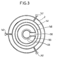
- FIG. 3 shows a section of the separator, according to III of Figure 2.
- the straightening device 104 has not been shown.
- the fixing means of the skirt are six screws 142, distributed on two different planes (see Figure 2), and 120 ° in the same plane.
- the skirt 141 may be provided with holes facing the discharge pipe 109. These holes make it possible to discharge the liquid which would accumulate in the lower part of the skirt.
- FIG. 4 represents a variant of the central hub made up of several parts and comprising other reinjection channels.
- FIG. 4 there is shown an axial hub 120, a circulation tube 100 and a distributor 102 fixed on the hub 120 and on the tube 100.
- the hub 120 consists of three parts 120A, 120B, 120'B, the parts 120B, 120 ′ B which can of course be produced in one.
- One end of the part 120A represents an external annular bearing surface 125, and one end of the part 120B represents an internal annular bearing surface 126. Between these two bearing surfaces 125, 126, blades 120C, better visible in FIG. 5, are welded inclined relative to to a radial plane in order to impart to the vapor-water mixture reinjected a vortex movement in the same direction as that of the mixture leaving the distributor 102.
- the reinjection channels 116A are also visible in this FIG. 5.
- the central part 120B, as well as the end of the part 120'B in this example have an outer diameter reduced compared to the part 120A to compensate for the increase in flow rate.
- the outside diameter of the part 120 ′ takes the value of the diameter of the part 120A, around the entrance to the collection tube 103.
Landscapes
- Chemical & Material Sciences (AREA)
- Chemical Kinetics & Catalysis (AREA)
- Cyclones (AREA)
- Separating Particles In Gases By Inertia (AREA)
- Centrifugal Separators (AREA)
Claims (7)
Applications Claiming Priority (4)
| Application Number | Priority Date | Filing Date | Title |
|---|---|---|---|
| FR8408085A FR2564750B1 (fr) | 1984-05-23 | 1984-05-23 | Separateur de melanges par centrifugation |
| FR8408085 | 1984-05-23 | ||
| FR8501015 | 1985-01-24 | ||
| FR858501015A FR2576224B2 (fr) | 1985-01-24 | 1985-01-24 | Separateur de melanges par centrifugation |
Publications (3)
| Publication Number | Publication Date |
|---|---|
| EP0162441A2 EP0162441A2 (de) | 1985-11-27 |
| EP0162441A3 EP0162441A3 (en) | 1986-06-11 |
| EP0162441B1 true EP0162441B1 (de) | 1989-07-26 |
Family
ID=26223984
Family Applications (1)
| Application Number | Title | Priority Date | Filing Date |
|---|---|---|---|
| EP85106204A Expired EP0162441B1 (de) | 1984-05-23 | 1985-05-21 | Zentrifugalseparator für Gemische |
Country Status (6)
| Country | Link |
|---|---|
| US (1) | US4650578A (de) |
| EP (1) | EP0162441B1 (de) |
| KR (1) | KR920006877B1 (de) |
| CA (1) | CA1260410A (de) |
| DE (1) | DE3571771D1 (de) |
| ES (1) | ES8607760A1 (de) |
Cited By (1)
| Publication number | Priority date | Publication date | Assignee | Title |
|---|---|---|---|---|
| US11199111B2 (en) | 2016-07-14 | 2021-12-14 | General Electric Company | Assembly for particle removal |
Families Citing this family (26)
| Publication number | Priority date | Publication date | Assignee | Title |
|---|---|---|---|---|
| EP0232688A1 (de) * | 1986-01-09 | 1987-08-19 | L.C.M. LAVORAZIONE COMPONENTI MECCANICHE S.r.L. | Vorrichtung zur Abtrennung von Partikeln, die in einem Auslass-Gasstrom enthalten sind, insbesondere für Luftkompressoren und dergleichen |
| US5009796A (en) * | 1986-03-24 | 1991-04-23 | Robert Adler | Methods and apparatus for treating a mixture of particles and fluids |
| FR2630027B1 (fr) * | 1988-04-19 | 1991-07-12 | Stein Industrie | Separateur de melanges par centrifugation |
| NL1010478C2 (nl) * | 1998-11-04 | 2000-05-08 | Cds Engineering B V | Inrichting voor het behandelen van een gas/vloeistofmengsel. |
| SE515552C2 (sv) | 1998-12-15 | 2001-08-27 | Vattenfall Ab | Anordning för avskiljning av fasta objekt ur en strömmande fluid |
| FR2795345B1 (fr) * | 1999-06-25 | 2001-09-28 | Devauze Venclim | Separateur a cyclone |
| NO321170B1 (no) * | 2002-06-21 | 2006-03-27 | Statoil Asa | Sammenstilling for a separere ut vaeske fra en flerfasestrom |
| US7241392B2 (en) * | 2004-09-09 | 2007-07-10 | Dresser-Rand Company | Rotary separator and method |
| US10286407B2 (en) | 2007-11-29 | 2019-05-14 | General Electric Company | Inertial separator |
| JP5550318B2 (ja) | 2009-12-10 | 2014-07-16 | 三菱重工業株式会社 | 多段気水分離装置、および気水分離器 |
| EP2533905B1 (de) | 2010-02-10 | 2018-07-04 | Dresser-Rand Company | Separatorflüssigkeitsbehälter und verfahren dafür |
| US8673159B2 (en) | 2010-07-15 | 2014-03-18 | Dresser-Rand Company | Enhanced in-line rotary separator |
| WO2012009159A2 (en) | 2010-07-15 | 2012-01-19 | Dresser-Rand Company | Radial vane pack for rotary separators |
| WO2012012018A2 (en) | 2010-07-20 | 2012-01-26 | Dresser-Rand Company | Combination of expansion and cooling to enhance separation |
| US8821362B2 (en) | 2010-07-21 | 2014-09-02 | Dresser-Rand Company | Multiple modular in-line rotary separator bundle |
| EP2614216B1 (de) | 2010-09-09 | 2017-11-15 | Dresser-Rand Company | Spülungsaktivierter gesteuerter strömungsabfluss |
| US11033845B2 (en) | 2014-05-29 | 2021-06-15 | General Electric Company | Turbine engine and particle separators therefore |
| CA2949547A1 (en) | 2014-05-29 | 2016-02-18 | General Electric Company | Turbine engine and particle separators therefore |
| EP3149310A2 (de) | 2014-05-29 | 2017-04-05 | General Electric Company | Turbinenmotor, komponenten und verfahren zur kühlung davon |
| US9915176B2 (en) | 2014-05-29 | 2018-03-13 | General Electric Company | Shroud assembly for turbine engine |
| CN104141775B (zh) * | 2014-07-03 | 2016-04-20 | 中国航空动力机械研究所 | 用于动力装置齿轮箱的油气分离器及航空发动机 |
| US10167725B2 (en) | 2014-10-31 | 2019-01-01 | General Electric Company | Engine component for a turbine engine |
| US10036319B2 (en) | 2014-10-31 | 2018-07-31 | General Electric Company | Separator assembly for a gas turbine engine |
| US10428664B2 (en) | 2015-10-15 | 2019-10-01 | General Electric Company | Nozzle for a gas turbine engine |
| US9988936B2 (en) | 2015-10-15 | 2018-06-05 | General Electric Company | Shroud assembly for a gas turbine engine |
| CN108999605A (zh) * | 2018-05-31 | 2018-12-14 | 滨州学院 | 一种气井井口管式外循环旋流脱水装置 |
Family Cites Families (9)
| Publication number | Priority date | Publication date | Assignee | Title |
|---|---|---|---|---|
| FR961953A (de) * | 1950-05-26 | |||
| US1069048A (en) * | 1913-04-19 | 1913-07-29 | Richard F Grant | Apparatus for separating solids from liquids. |
| BE502624A (de) * | 1950-04-22 | |||
| GB727137A (en) * | 1951-09-20 | 1955-03-30 | Stephen Percival Chard | Improvements in and relating to centrifugal separators |
| US2787378A (en) * | 1952-05-26 | 1957-04-02 | Everett M Battey | Slurry type liquid treating apparatus |
| US2921646A (en) * | 1957-01-31 | 1960-01-19 | Fairchild Engine & Airplane | Moisture separator |
| FR1522028A (fr) * | 1966-05-23 | 1968-04-19 | Gen Electric | Séparateur du type cyclone |
| DE2256678A1 (de) * | 1972-11-18 | 1974-05-22 | Koerting Ag | Fliehkraftabscheider |
| DE2960977D1 (en) * | 1978-05-12 | 1981-12-24 | Stein Industrie | Vertical separator of a mixture of steam or gas and liquid or solid particles |
-
1985
- 1985-05-21 DE DE8585106204T patent/DE3571771D1/de not_active Expired
- 1985-05-21 EP EP85106204A patent/EP0162441B1/de not_active Expired
- 1985-05-22 CA CA000482097A patent/CA1260410A/fr not_active Expired
- 1985-05-22 ES ES543392A patent/ES8607760A1/es not_active Expired
- 1985-05-23 US US06/736,999 patent/US4650578A/en not_active Expired - Lifetime
- 1985-05-23 KR KR1019850003544A patent/KR920006877B1/ko not_active IP Right Cessation
Cited By (1)
| Publication number | Priority date | Publication date | Assignee | Title |
|---|---|---|---|---|
| US11199111B2 (en) | 2016-07-14 | 2021-12-14 | General Electric Company | Assembly for particle removal |
Also Published As
| Publication number | Publication date |
|---|---|
| EP0162441A2 (de) | 1985-11-27 |
| EP0162441A3 (en) | 1986-06-11 |
| CA1260410A (fr) | 1989-09-26 |
| ES8607760A1 (es) | 1986-06-01 |
| ES543392A0 (es) | 1986-06-01 |
| KR920006877B1 (ko) | 1992-08-21 |
| KR850008104A (ko) | 1985-12-13 |
| US4650578A (en) | 1987-03-17 |
| DE3571771D1 (en) | 1989-08-31 |
Similar Documents
| Publication | Publication Date | Title |
|---|---|---|
| EP0162441B1 (de) | Zentrifugalseparator für Gemische | |
| FR2742804A1 (fr) | Rotor deshuileur pour enceinte de lubrification | |
| CA2637643C (fr) | Separateur a ecoulement cyclonique | |
| CA2038810C (fr) | Systeme desaerateur d'huile | |
| FR2694051A1 (fr) | Compresseur à vis muni de moyens pour séparer l'huile du courant d'huile-gaz refoulé par ce compresseur. | |
| FR3052522A1 (fr) | Dispositif de recuperation d'huile de lubrification ejectee par effet centrifuge dans une turbomachine | |
| FR2533621A1 (fr) | Generateur du type a thermosiphon | |
| EP3669964B1 (de) | Vorrichtung zum trennen eines luft-öl-gemisches | |
| EP0246151A1 (de) | Abscheider mit Flügelflächen zur Abscheidung von Flüssigkeitsteilchen | |
| FR2460701A1 (fr) | Dispositif de separation de matieres solides dans un courant de liquide | |
| FR2556778A1 (fr) | Dispositif de separation gaz-liquide et son application au deshuilage de l'air de ventilation des enceintes de paliers d'une turbomachine | |
| FR2558741A1 (fr) | Separateur de melanges par centrifugation | |
| FR2589957A1 (fr) | Compresseur de fluide gazeux, associe a un separateur gaz-liquide | |
| FR2644084A1 (fr) | Separateur de melanges par centrifugation | |
| FR2588778A1 (fr) | Separateur a vortex liquide | |
| FR2516810A1 (fr) | Passage d'introduction de fluide a l'interieur d'une enveloppe de reacteur | |
| FR2855078A1 (fr) | Dispositif de separation comportant un electro-coalesceur tubulaire | |
| FR2630027A1 (fr) | Separateur de melanges par centrifugation | |
| EP0241345A1 (de) | Kernreaktor mit Strömungsführung in den oberen inneren Einbauten | |
| FR2564750A1 (fr) | Separateur de melanges par centrifugation | |
| FR2602697A1 (fr) | Bol centrifuge pour clarifier ou separer des liquides a centrifuger | |
| FR2576224A2 (fr) | Separateur de melanges par centrifugation | |
| EP0366639B1 (de) | Vorrichtung zur Kühlung eines sich bewegenden zylindrischen Elements | |
| EP0002235A1 (de) | Senkrechter Abscheider für eine Dampfflüssigkeitsmischung | |
| FR2497682A1 (fr) | Procede et dispositif de traitement d'un fluide en vue d'en extraire une phase gazeuse |
Legal Events
| Date | Code | Title | Description |
|---|---|---|---|
| PUAI | Public reference made under article 153(3) epc to a published international application that has entered the european phase |
Free format text: ORIGINAL CODE: 0009012 |
|
| AK | Designated contracting states |
Designated state(s): BE CH DE FR GB IT LI SE |
|
| PUAL | Search report despatched |
Free format text: ORIGINAL CODE: 0009013 |
|
| AK | Designated contracting states |
Kind code of ref document: A3 Designated state(s): BE CH DE FR GB IT LI SE |
|
| 17P | Request for examination filed |
Effective date: 19861211 |
|
| 17Q | First examination report despatched |
Effective date: 19871126 |
|
| GRAA | (expected) grant |
Free format text: ORIGINAL CODE: 0009210 |
|
| AK | Designated contracting states |
Kind code of ref document: B1 Designated state(s): BE CH DE FR GB IT LI SE |
|
| REF | Corresponds to: |
Ref document number: 3571771 Country of ref document: DE Date of ref document: 19890831 |
|
| ITF | It: translation for a ep patent filed | ||
| GBT | Gb: translation of ep patent filed (gb section 77(6)(a)/1977) | ||
| PLBE | No opposition filed within time limit |
Free format text: ORIGINAL CODE: 0009261 |
|
| STAA | Information on the status of an ep patent application or granted ep patent |
Free format text: STATUS: NO OPPOSITION FILED WITHIN TIME LIMIT |
|
| 26N | No opposition filed | ||
| REG | Reference to a national code |
Ref country code: FR Ref legal event code: AM |
|
| REG | Reference to a national code |
Ref country code: FR Ref legal event code: CL |
|
| ITTA | It: last paid annual fee | ||
| EAL | Se: european patent in force in sweden |
Ref document number: 85106204.2 |
|
| REG | Reference to a national code |
Ref country code: GB Ref legal event code: IF02 |
|
| PGFP | Annual fee paid to national office [announced via postgrant information from national office to epo] |
Ref country code: CH Payment date: 20020416 Year of fee payment: 18 |
|
| PGFP | Annual fee paid to national office [announced via postgrant information from national office to epo] |
Ref country code: SE Payment date: 20020502 Year of fee payment: 18 Ref country code: GB Payment date: 20020502 Year of fee payment: 18 |
|
| PGFP | Annual fee paid to national office [announced via postgrant information from national office to epo] |
Ref country code: DE Payment date: 20020511 Year of fee payment: 18 |
|
| PGFP | Annual fee paid to national office [announced via postgrant information from national office to epo] |
Ref country code: FR Payment date: 20020513 Year of fee payment: 18 |
|
| PGFP | Annual fee paid to national office [announced via postgrant information from national office to epo] |
Ref country code: BE Payment date: 20020527 Year of fee payment: 18 |
|
| PG25 | Lapsed in a contracting state [announced via postgrant information from national office to epo] |
Ref country code: GB Free format text: LAPSE BECAUSE OF NON-PAYMENT OF DUE FEES Effective date: 20030521 |
|
| PG25 | Lapsed in a contracting state [announced via postgrant information from national office to epo] |
Ref country code: SE Free format text: LAPSE BECAUSE OF NON-PAYMENT OF DUE FEES Effective date: 20030522 |
|
| PG25 | Lapsed in a contracting state [announced via postgrant information from national office to epo] |
Ref country code: LI Free format text: LAPSE BECAUSE OF NON-PAYMENT OF DUE FEES Effective date: 20030531 Ref country code: CH Free format text: LAPSE BECAUSE OF NON-PAYMENT OF DUE FEES Effective date: 20030531 Ref country code: BE Free format text: LAPSE BECAUSE OF NON-PAYMENT OF DUE FEES Effective date: 20030531 |
|
| BERE | Be: lapsed |
Owner name: *ELECTRICITE DE FRANCE SERVICE NATIONAL Effective date: 20030531 Owner name: *STEIN INDUSTRIE Effective date: 20030531 |
|
| PG25 | Lapsed in a contracting state [announced via postgrant information from national office to epo] |
Ref country code: DE Free format text: LAPSE BECAUSE OF NON-PAYMENT OF DUE FEES Effective date: 20031202 |
|
| EUG | Se: european patent has lapsed | ||
| GBPC | Gb: european patent ceased through non-payment of renewal fee |
Effective date: 20030521 |
|
| REG | Reference to a national code |
Ref country code: CH Ref legal event code: PL |
|
| PG25 | Lapsed in a contracting state [announced via postgrant information from national office to epo] |
Ref country code: FR Free format text: LAPSE BECAUSE OF NON-PAYMENT OF DUE FEES Effective date: 20040130 |
|
| REG | Reference to a national code |
Ref country code: FR Ref legal event code: ST |