EP0366639B1 - Vorrichtung zur Kühlung eines sich bewegenden zylindrischen Elements - Google Patents
Vorrichtung zur Kühlung eines sich bewegenden zylindrischen Elements Download PDFInfo
- Publication number
- EP0366639B1 EP0366639B1 EP89870150A EP89870150A EP0366639B1 EP 0366639 B1 EP0366639 B1 EP 0366639B1 EP 89870150 A EP89870150 A EP 89870150A EP 89870150 A EP89870150 A EP 89870150A EP 0366639 B1 EP0366639 B1 EP 0366639B1
- Authority
- EP
- European Patent Office
- Prior art keywords
- tubular pipe
- cooling
- annular chamber
- rings
- passages
- Prior art date
- Legal status (The legal status is an assumption and is not a legal conclusion. Google has not performed a legal analysis and makes no representation as to the accuracy of the status listed.)
- Expired - Lifetime
Links
Images

Classifications
-
- B—PERFORMING OPERATIONS; TRANSPORTING
- B21—MECHANICAL METAL-WORKING WITHOUT ESSENTIALLY REMOVING MATERIAL; PUNCHING METAL
- B21B—ROLLING OF METAL
- B21B45/00—Devices for surface or other treatment of work, specially combined with or arranged in, or specially adapted for use in connection with, metal-rolling mills
- B21B45/02—Devices for surface or other treatment of work, specially combined with or arranged in, or specially adapted for use in connection with, metal-rolling mills for lubricating, cooling, or cleaning
- B21B45/0203—Cooling
- B21B45/0209—Cooling devices, e.g. using gaseous coolants
- B21B45/0215—Cooling devices, e.g. using gaseous coolants using liquid coolants, e.g. for sections, for tubes
- B21B45/0224—Cooling devices, e.g. using gaseous coolants using liquid coolants, e.g. for sections, for tubes for wire, rods, rounds, bars
Definitions
- the present invention relates to a device for cooling a cylindrical element in movement, making it possible to ensure homogeneous cooling of this element according to the preamble of claim 1; see US-A-4,507,949.
- cylindrical element in movement means a product of elongated shape, for example a bar or a tube, which moves along its longitudinal axis.
- the device of the invention is particularly intended for the cooling of a steel product, from the rolling temperature at the outlet of a rolling mill. However, it can also be used for cooling after any forming or heat treatment operation.
- Devices for cooling a cylindrical steel element in movement at the outlet of a rolling mill have been known for a long time, which in particular use sprinkler rings or circumferential slots to distribute the coolant on the surface of the element .
- the cooling provided by such devices is generally not sufficiently rapid and homogeneous both over the perimeter and over the length of the cylindrical element in movement, in particular when this cooling conditions certain final properties of the element.
- the properties targeted are linked to obtaining an appropriate structure, for example a hardened and self-returning surface layer or else a fine-grained ferritic structure when it is steel.
- the present invention provides a device for ensuring cooling of a cylindrical element in movement, which does not have the aforementioned drawbacks of insufficient speed and homogeneity, and therefore making it possible to confer on the cylindrical element, the desired structure and properties.
- a device for cooling a cylindrical element in movement, by means of a cooling agent which comprises a continuous rectilinear tubular conduit, open at its two ends, inside which the element passes cylindrical to be cooled, with a continuous envelope surrounding said tubular conduit and forming with it a continuous annular chamber, said continuous annular chamber being closed at its ends respectively by an upstream wall and a downstream wall, and in which it is provided means for introducing the coolant into said continuous annular chamber and means for discharging said coolant from the interior volume of said continuous tubular duct, is characterized in that said tubular duct is pierced with a plurality of equidistant radial rectilinear passages communicating said continuous annular chamber with the interior volume of said tubular conduit, in that said rectilinear radial passages are arranged in flat rings perpendicular to the longitudinal axis of said tubular conduit, and in that each ring is angularly offset with respect to the neighboring ring.
- the radial passages are distributed in one or more groups of at least three equidistant rings; in each group, each crown preferably has the same number of passages, with the consequence that the equidistance of the passages in a crown is identical in all the crowns of the same group; finally, the offset angle between two neighboring crowns is advantageously the same for all the crowns of the same group.
- the means for introducing the cooling agent into the annular chamber are usual and therefore do not form part of the object of the present invention. They are for example constituted by a supply line connected to a source of cooling agent and opening laterally into said annular chamber. In general, this supply line opens radially into the annular chamber.
- a deflector is advantageously provided opposite the mouth of the supply line; such a deflector makes it possible to avoid a direct effect of the cooling agent leaving the supply line on the flow rate of said agent in the radial passages located opposite the mouth of said supply line.
- the means for removing the cooling agent comprise at least one transverse passage located at the upstream end of said tubular conduit.
- a plurality of these transverse passages is preferably provided, distributed uniformly along the periphery of said tubular conduit. Even more advantageously, these transverse passages are joined in a continuous peripheral slot which connects the internal volume of said tubular conduit and external means for receiving the cooling agent.
- said transverse slot is formed between the closure wall of the upstream end of said annular chamber and an outer annular plate disposed at a certain distance upstream from this wall and extending radially in front of at least one part of the inlet opening of said tubular conduit.
- the radially inner edge of said annular plate is advantageously profiled in a funnel, in order to serve as a guide for the entry of the cylindrical element in movement to be cooled in said tubular conduit.
- the device of the invention also comprises retaining means to prevent the coolant from escaping through the inlet and outlet openings of the cylindrical element in said tubular conduit and thus of the '' force to evacuate through the transverse passages or the transverse slot described above.
- These retaining means can be mechanical in nature, such as plates pierced with a calibrated opening to allow passage to the cylindrical element; they can also be of a hydraulic or pneumatic nature, such as jets of liquid or gas under pressure forming a screen at the inlet and at the outlet of said tubular conduit.
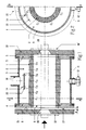
- FIG. 1 shows a longitudinal section through a device for cooling a scrolling cylindrical element.
- This device comprises a tubular conduit 1, through which the cylindrical element to be cooled circulates, symbolically shown in phantom.
- the tubular conduit 1 is surrounded by an annular chamber 2, which is delimited externally by a generally cylindrical envelope 3.
- chamber 2 is closed at its ends by walls 4, 5 provided with centering projections 6, 7.
- These walls 4, 5 are fixed to the casing 3 by means of bolts symbolized by their axes. They are pierced with central openings 8, 9 positioned in the extension of the interior passage of the tubular conduit 1.
- the annular chamber 2 is connected by a supply line 10 to a source of cooling agent, not shown. It also has an orifice 11 which, in operation, is normally covered by a plug 12, but which can for example be used to measure the pressure in the chamber 2; this orifice 11 also makes it possible to empty and clean the chamber 2.
- the tubular conduit 1 is pierced with radial passages such as C5, distributed in crowns as will be seen more clearly in FIGS. 3 and 4.
- a deflector Faced with the mouth of the supply line 10, a deflector is provided, for example by a plate 13 welded to the casing 3 by means of rods 14.
- the plate 13 covers, at a distance, the inlet orifice of the radial passages situated opposite the mouth of the supply line 10; it thus avoids an excessively direct effect of the supply flow on the flow in the above-mentioned radial passages and therefore contributes to a more homogeneous distribution of the cooling agent in all of these radial passages.
- an external plate 15 pierced with a central opening 16 shaped in a funnel to facilitate the introduction of the cylindrical element to be cooled.
- This central opening has, at its narrowest part, a diameter slightly greater than the outside diameter of the cylindrical element. It is advantageous to constitute a set of several plates having different opening diameters, suitable for the range of dimensions of the cylindrical elements to be cooled.
- the "inside" face of this plate (15) is provided with spacing means such as lugs 17 automatically ensuring the desired spacing "e” between the plate 15 and the upstream wall 4.
- the plate 15 can still be provided, on its “outer” face, with a flap 18 symbolized in phantom, intended to improve the retention of the cooling agent.
- another external plate 19 is applied against the downstream wall 5; it is also pierced with a central opening 20 shaped in a funnel and having a diameter suitable for the dimension of the cylindrical element.
- the constitution of a set of plates 19 makes it possible to use in each case the plate best suited to the outside diameter of the cylindrical element to be treated.
- a flap 18 ′ can also complete the device.
- the flaps 18 and 18 ′ are preferably made of a flexible material such as silicone.
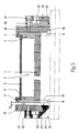
- FIG. 2 essentially shows the position of the deflection plate 13 and the support rods 14 with respect to the radial passages such as C1 situated opposite the mouth of the supply line 10. It also illustrates the arrangement of a crown radial passages, in this case the passages C1.
- FIGS. 3 and 4 illustrate, respectively in longitudinal section and in cross section, the constitution of a tubular conduit intended for the device of FIG. 1.
- FIG. 3 shows that the radial passages are distributed in rings C1 ... C7 along planes perpendicular to the axis of the tubular conduit 1.
- the crowns of passages C1 to C7 are equidistant in the longitudinal direction, and they are angularly offset, with respect to each other, by a constant angle which is here 360 ° / 56, two successive radial passages of the same crown always separated by an angle of 45 °.
- the orifices of the radial passages draw helical lines in the interior, respectively exterior surfaces of the tubular conduit 1.
- the offset angle between two successive rings is 360 ° / (N.n), where N and n represent the number of rings and the number of radial passages in each ring respectively.
- tubular conduit 1 could, without departing from the scope of the invention, have several groups of crowns succeeding one another in the longitudinal direction, the values of N and n possibly also varying from one group to another .
- FIG. 5 illustrates variants of devices intended to form screens for retaining the cooling agent at the inlet and at the outlet of the tubular conduit 1.
- the upstream plate 15 is provided, at its inner edge, with an attached flange 21, profiled in a funnel.
- an annular stirrup 22 having a lip 23 which forms with the collar 21 a slot 24 inclined in the direction of progression of the cylindrical element. This slot communicates with a distribution cavity 25 formed in the stirrup 22 and itself connected to a source of coolant, not shown.
- the outer face of the lip 23 is profiled in a funnel and constitutes the inlet guide of the cylindrical element to be cooled.
- Radially, the flange 21 is slightly set back relative to the lip 23, in order to avoid any untimely hooking of the incoming cylindrical element.
- the downstream plate 19 carries an annular assembly consisting of a base 26 and a cover 27.
- the base 26 is applied to the plate 19 and its radially inner edge has a profile diverge.
- the cover 27 ends with a lip 28 which, at a distance, follows the divergent profile of the base, thereby forming a slot 29, inclined in the direction opposite to the progression of the cylindrical element, which communicates by a distribution cavity. 30 provided in the base 26, with a source of coolant, not shown.
- the end of the lip 28 is radially slightly set back relative to the neck of the converging profile of the downstream plate 19, in order to avoid any undesirable catching of the cylindrical element.
- the cooling agent usually water
- the cooling agent is introduced via the supply line 10, into the annular chamber 2, from which it flows through the radial passages C1 ... C7 to fill the space. between the tubular conduit 1 and the cylindrical element to be cooled. Due to the aforementioned retaining means, the coolant then escapes through the slot "e" between the wall 4 and the plate 15, thus creating a counter-current circulation which has been found to be particularly favorable for cooling. of the cylindrical element.
- the coolant jets exiting the radial passages agitate the coolant and prevent the formation of a caulking layer on the surface of the cylindrical member.
- a tubular conduit 1 with an inside diameter of 106 mm makes it possible to treat cylindrical elements having an outside diameter of between 340 mm and 90 mm.
- tubes having an outside diameter of 90 mm and a wall thickness of 6.5 mm were cooled in a device whose tubular duct had an inside diameter of 106 mm. This duct had 56 radial passages of 2 mm in diameter, divided into 7 crowns.
Landscapes
- Engineering & Computer Science (AREA)
- Mechanical Engineering (AREA)
- Physical Or Chemical Processes And Apparatus (AREA)
- Heat Treatments In General, Especially Conveying And Cooling (AREA)
- Heat Treatment Of Articles (AREA)
- Heat-Exchange Devices With Radiators And Conduit Assemblies (AREA)
- Turning (AREA)
Claims (9)
- Kühlvorrichtung für einen sich vorwärtsbewegenden zylinderförmigen Gegenstand mit Hilfe eines Kühlmittels, bestehend aus einem geraden, durchlaufenden, an seinen beiden Enden offenen, rohrförmigen, von dem zu kühlenden zylinderförmigen Gegenstand durchlaufenen Kanal (1), mit einem besagten rohrförmigen Kanal (1) umgebenden und mit diesem eine durchlaufende ringförmige Kammer (2) bildenden durchlaufenden Mantel (3), wobei diese durchlaufende ringförmige Kammer (2) an ihren Enden durch eine stromaufwärtige (4) bzw. stromabwärtige (5) Wand abgeschlossen ist, und worin Mittel (10) zum Einführen des Kühlmittels in diese durchlaufende ringförmige Kammer (2) und Mittel zu dessen Abziehen aus dem Innenvolumen jenes durchlaufenden rohrförmigen Kanals (1) vorgesehen sind, dadurch gekennzeichnet, daß besagter rohrförmiger Kanal (1) von einer Mehrzahl radialer, geradliniger, auf gleichen Abständen liegender Durchgänge (C1...C7) durchsetzt ist, welche jene durchlaufende ringförmige Kammer (2) mit dem Innenvolumen jenes rohrförmigen Kanals (1) in Verbindung bringen, daß diese radialen geradlinigen Durchgänge (C1...C7) in zur Längsachse besagten rohrförmigen Kanals (1) senkrechten, ebenen Ringen angeordnet sind und daß die Ringe jeweils unter einem Winkel gegenüber dem benachbarten Ring versetzt sind.
- Kühlvorrichtung nach Anspruch 1, dadurch gekennzeichnet, daß jener rohrförmige Kanal (1) eine oder mehrere Gruppen von mindestens drei Durchgangsringen aufweist und daß die Ringe ein und derselben Gruppe auf gleichen Abständen liegen.
- Kühlvorrichtung nach einem der Ansprüche 1 und 2, dadurch gekennzeichnet, daß der Versetzungswinkel zwischen zwei benachbarten Ringen für alle Ringe ein und derselben Gruppe gleich ist.
- Kühlvorrichtung nach Anspruch 3, dadurch gekennzeichnet, daß dieser Versetzungswinkel der Ringe ein und derselben Gruppe gleich 360°/(N.n) ist, wobei N die Anzahl der Ringe dieser Gruppe und n die Anzahl der Durchgänge jedes Rings in besagter Gruppe ist.
- Kühlvorrichtung nach einem der Ansprüche 1 bis 4, dadurch gekennzeichnet, daß im Inneren besagter ringförmiger Kammer (2) eine Leitplatte (13) vorgesehen ist, um eine homogene Verteilung des Kühlmittels in besagten Durchgängen (C1...C7) sicherzustellen.
- Kühlvorrichtung nach einem der Ansprüche 1 bis 5, dadurch gekennzeichnet, daß jene Mittel zum Abziehen des Kühlmittels mindestens einen am stromaufwärtigen Ende besagten rohrförmigen Kanals (1) liegenden Querdurchgang umfassen.
- Kühlvorrichtung nach Anspruch 6, dadurch gekennzeichnet, daß dieser Querdurchgang zwischen der Abschlußwand (4) des stromaufwärtigen Endes jener ringförmigen Kammer (2) und einer äußeren ringförmigen Platte (15) gebildet ist, die in einem gewissen Abstand (e) stromaufwärts dieser Wand (4) angeordnet ist und sich radial vor mindestens einem Teil der Eingangsöffnung (8) jenes rohrförmigen Kanals (1) erstreckt.
- Kühlvorrichtung nach einem der Ansprüche 1 bis 7, dadurch gekennzeichnet, daß sie Rückhaltemittel enthält, um ein Ausströmen des Kühlmittels durch die Eingangsöffnungen (8) und Ausgangsöffnungen (9) des zylinderförmigen Gegenstands in besagtem rohrförmigem Kanal (1) zu verhindern.
- Kühlvorrichtung nach Anspruch 8, dadurch gekennzeichnet, daß diese Rückhaltemittel aus von einer kalibrierten Öffnung (16; 20) durchbrochenen Endplatten (15, 18; 19, 18') und/oder aus Vorrichtungen (21, 22, 23; 26, 27) zur Bildung flüssiger oder gasförmiger Abschirmungen am Eingang (8) und/oder Ausgang (9) jenes rohrförmigen Kanals (1) bestehen.
Applications Claiming Priority (2)
| Application Number | Priority Date | Filing Date | Title |
|---|---|---|---|
| BE8801224A BE1002565A6 (fr) | 1988-10-24 | 1988-10-24 | Dispositif de refroidissement d'un element cylindrique en defilement. |
| BE8801224 | 1988-10-24 |
Publications (3)
| Publication Number | Publication Date |
|---|---|
| EP0366639A2 EP0366639A2 (de) | 1990-05-02 |
| EP0366639A3 EP0366639A3 (de) | 1991-06-12 |
| EP0366639B1 true EP0366639B1 (de) | 1994-08-31 |
Family
ID=3883695
Family Applications (1)
| Application Number | Title | Priority Date | Filing Date |
|---|---|---|---|
| EP89870150A Expired - Lifetime EP0366639B1 (de) | 1988-10-24 | 1989-10-11 | Vorrichtung zur Kühlung eines sich bewegenden zylindrischen Elements |
Country Status (7)
| Country | Link |
|---|---|
| US (1) | US5035403A (de) |
| EP (1) | EP0366639B1 (de) |
| JP (1) | JPH02258111A (de) |
| AT (1) | ATE110600T1 (de) |
| BE (1) | BE1002565A6 (de) |
| CA (1) | CA2001183A1 (de) |
| DE (1) | DE68917855D1 (de) |
Families Citing this family (5)
| Publication number | Priority date | Publication date | Assignee | Title |
|---|---|---|---|---|
| BE1003665A6 (fr) * | 1990-02-01 | 1992-05-19 | Centre Rech Metallurgique | Dispositif et procede pour le refroidissement module d'un element cylindrique en defilement. |
| BE1003667A6 (fr) * | 1990-02-20 | 1992-05-19 | Centre Rech Metallurgique | Dispositif de refroidissement d'un element cylindrique en defilement. |
| IT1288066B1 (it) * | 1996-01-26 | 1998-09-10 | Metalrame S R L | Scambiatore di calore a doppia camera atto a consentire un rapido ed elevato salto termico particolarmente adatto per il raffredamento |
| US6656413B2 (en) * | 2001-06-21 | 2003-12-02 | Can-Eng Furnaces Ltd | Method and apparatus for quenching metal workpieces |
| US7257976B1 (en) * | 2007-01-10 | 2007-08-21 | Mario Fabris | Spiral cooling of steel workpiece in a rolling process |
Family Cites Families (11)
| Publication number | Priority date | Publication date | Assignee | Title |
|---|---|---|---|---|
| US2565855A (en) * | 1947-11-19 | 1951-08-28 | Selas Corp Of America | Plural station quenching device for elongated objects |
| FR1421811A (fr) * | 1964-01-13 | 1965-12-17 | Morgan Construction Co | Procédé et appareil de refroidissement réglé pour un laminoir de fil machine |
| DE2251244C3 (de) * | 1972-10-19 | 1975-12-04 | Baustahlgewebe Gmbh, 4000 Duesseldorf | Vorrichtung zum Versprühen eines flussigen Kuhlmediums zur Abkühlung von warmebehandeltem Draht in kontinuierlichem Durchlauf |
| NL163142C (nl) * | 1973-06-04 | 1980-08-15 | Hoogovens Ijmuiden Bv | Inrichting voor het met water koelen van warmgewalst staafmateriaal. |
| JPS5214507A (en) * | 1975-07-24 | 1977-02-03 | Nippon Steel Corp | Process for quenching a hot rolled wire |
| DD143142B1 (de) * | 1979-05-18 | 1982-06-30 | Walter Worgt | Kuehlsystem bei drahtwindungslegern |
| JPS5638427A (en) * | 1979-09-05 | 1981-04-13 | Sumitomo Electric Ind Ltd | Cooler for hardening steel wire |
| JPS6020450B2 (ja) * | 1980-07-04 | 1985-05-22 | 新日本製鐵株式会社 | 棒線均一冷却装置 |
| US4507949A (en) * | 1982-02-12 | 1985-04-02 | Republic Steel Corporation | Apparatus for cooling a hot-rolled product |
| IT1177873B (it) * | 1984-07-04 | 1987-08-26 | Centro Speriment Metallurg | Dispositivo per il raffredamento di laminati a caldo piani |
| DE3424550A1 (de) * | 1984-07-04 | 1986-01-16 | Fried. Krupp Gmbh, 4300 Essen | Kuehlmittel-zufuehreinrichtung |
-
1988
- 1988-10-24 BE BE8801224A patent/BE1002565A6/fr not_active IP Right Cessation
-
1989
- 1989-10-11 EP EP89870150A patent/EP0366639B1/de not_active Expired - Lifetime
- 1989-10-11 AT AT89870150T patent/ATE110600T1/de not_active IP Right Cessation
- 1989-10-11 DE DE68917855T patent/DE68917855D1/de not_active Expired - Lifetime
- 1989-10-23 CA CA002001183A patent/CA2001183A1/en not_active Abandoned
- 1989-10-24 US US07/426,119 patent/US5035403A/en not_active Expired - Fee Related
- 1989-10-24 JP JP1276970A patent/JPH02258111A/ja active Pending
Also Published As
| Publication number | Publication date |
|---|---|
| JPH02258111A (ja) | 1990-10-18 |
| EP0366639A2 (de) | 1990-05-02 |
| US5035403A (en) | 1991-07-30 |
| BE1002565A6 (fr) | 1991-03-26 |
| EP0366639A3 (de) | 1991-06-12 |
| DE68917855D1 (de) | 1994-10-06 |
| ATE110600T1 (de) | 1994-09-15 |
| CA2001183A1 (en) | 1990-04-24 |
Similar Documents
| Publication | Publication Date | Title |
|---|---|---|
| BE1004033A3 (fr) | Dispositif modulaire de distribution, destine a la distribution d'un courant de gaz, de preference dans un reacteur catalytique. | |
| EP0162441B1 (de) | Zentrifugalseparator für Gemische | |
| FR2507736A1 (fr) | Dispositif d'attenuation des bruits d'un fluide en ecoulement turbulent non symetrique par rapport a un axe | |
| FR2470321A1 (fr) | Vanne | |
| EP0366639B1 (de) | Vorrichtung zur Kühlung eines sich bewegenden zylindrischen Elements | |
| FR2643979A1 (fr) | Dispositif pour produire des projectiles conformes par explosif | |
| CH615606A5 (de) | ||
| EP0883731B1 (de) | Kernbohrwerkzeug | |
| WO2015170042A1 (fr) | Insert de decompression pour vanne rotative et vanne rotative equipee d'un tel insert | |
| EP0014140B1 (de) | Vorrichtung zum Abkühlen eines sich longitudinal fortbewegenden länglichen Gegenstandes | |
| EP2782471B1 (de) | Integraler diffusor für einen haartrockner | |
| EP0327526B1 (de) | Vorrichtung zum Kühlen eines Metalls während des Giessens | |
| FR2595432A1 (fr) | Ensemble de clapet anti-retour, notamment pour reacteur a eau pressurisee | |
| EP0202967B1 (de) | Speisewasservorwärmer für Dampferzeuger | |
| FR2464422A1 (fr) | Valve a haut rapport de reduction de la pression d'un fluide | |
| EP0163336A1 (de) | Vorrichtung zum Herstellen von Rohren aus molekular orientiertem Kunststoff | |
| EP0961894A1 (de) | Monostabiles ventil | |
| FR2701759A1 (fr) | Perfectionnement aux canons à neige. | |
| FR2496494A1 (fr) | Dispositif de refroidissement pour cylindres creux notamment de laminoirs broyeurs | |
| FR2633011A1 (fr) | Dispositif pour capter le jet de gaz d'echappement d'un reacteur d'aeronef et installation d'essais pour reacteur d'aeronef | |
| EP0829693B1 (de) | Dampf beheizte Riffelwalze | |
| FR2573960A1 (fr) | Dispositif homogeneiseur equipe d'un groupe obturateur perfectionne de commande de la distribution du produit, pour machines de fabrication de creme fouettee | |
| FR2786335A1 (fr) | Generateur, notamment alternateur pour vehicule automobile, a refroidissement par liquide | |
| FR2851293A1 (fr) | Dispositif de depollution des gaz d'echappement a organe de traitement amovible | |
| FR2572965A1 (fr) | Procede et dispositif de mise en compression par martelage d'un tube de generateur de vapeur serti dans une plaque tubulaire |
Legal Events
| Date | Code | Title | Description |
|---|---|---|---|
| PUAI | Public reference made under article 153(3) epc to a published international application that has entered the european phase |
Free format text: ORIGINAL CODE: 0009012 |
|
| AK | Designated contracting states |
Kind code of ref document: A2 Designated state(s): AT BE CH DE ES FR GB IT LI LU SE |
|
| PUAL | Search report despatched |
Free format text: ORIGINAL CODE: 0009013 |
|
| AK | Designated contracting states |
Kind code of ref document: A3 Designated state(s): AT BE CH DE ES FR GB IT LI LU SE |
|
| 17P | Request for examination filed |
Effective date: 19911113 |
|
| 17Q | First examination report despatched |
Effective date: 19930114 |
|
| GRAA | (expected) grant |
Free format text: ORIGINAL CODE: 0009210 |
|
| AK | Designated contracting states |
Kind code of ref document: B1 Designated state(s): AT BE CH DE ES FR GB IT LI LU SE |
|
| PG25 | Lapsed in a contracting state [announced via postgrant information from national office to epo] |
Ref country code: IT Free format text: LAPSE BECAUSE OF FAILURE TO SUBMIT A TRANSLATION OF THE DESCRIPTION OR TO PAY THE FEE WITHIN THE PRE;WARNING: LAPSES OF ITALIAN PATENTS WITH EFFECTIVE DATE BEFORE 2007 MAY HAVE OCCURRED AT ANY TIME BEFORE 2007. THE CORRECT EFFECTIVE DATE MAY BE DIFFERENT FROM THE ONE RECORDED.SCRIBED TIME-LIMIT Effective date: 19940831 Ref country code: ES Free format text: THE PATENT HAS BEEN ANNULLED BY A DECISION OF A NATIONAL AUTHORITY Effective date: 19940831 Ref country code: AT Effective date: 19940831 |
|
| REF | Corresponds to: |
Ref document number: 110600 Country of ref document: AT Date of ref document: 19940915 Kind code of ref document: T |
|
| REF | Corresponds to: |
Ref document number: 68917855 Country of ref document: DE Date of ref document: 19941006 |
|
| PGFP | Annual fee paid to national office [announced via postgrant information from national office to epo] |
Ref country code: BE Payment date: 19941012 Year of fee payment: 6 |
|
| PG25 | Lapsed in a contracting state [announced via postgrant information from national office to epo] |
Ref country code: LI Effective date: 19941031 Ref country code: CH Effective date: 19941031 |
|
| GBT | Gb: translation of ep patent filed (gb section 77(6)(a)/1977) |
Effective date: 19941024 |
|
| PG25 | Lapsed in a contracting state [announced via postgrant information from national office to epo] |
Ref country code: SE Effective date: 19941130 |
|
| PG25 | Lapsed in a contracting state [announced via postgrant information from national office to epo] |
Ref country code: DE Effective date: 19941201 |
|
| REG | Reference to a national code |
Ref country code: CH Ref legal event code: PL |
|
| PLBE | No opposition filed within time limit |
Free format text: ORIGINAL CODE: 0009261 |
|
| STAA | Information on the status of an ep patent application or granted ep patent |
Free format text: STATUS: NO OPPOSITION FILED WITHIN TIME LIMIT |
|
| 26N | No opposition filed | ||
| PGFP | Annual fee paid to national office [announced via postgrant information from national office to epo] |
Ref country code: LU Payment date: 19950901 Year of fee payment: 7 |
|
| PGFP | Annual fee paid to national office [announced via postgrant information from national office to epo] |
Ref country code: FR Payment date: 19950920 Year of fee payment: 7 |
|
| PGFP | Annual fee paid to national office [announced via postgrant information from national office to epo] |
Ref country code: GB Payment date: 19951002 Year of fee payment: 7 |
|
| PG25 | Lapsed in a contracting state [announced via postgrant information from national office to epo] |
Ref country code: BE Effective date: 19951031 |
|
| BERE | Be: lapsed |
Owner name: CENTRE DE RECHERCHES METALLURGIQUES CENTRUM VOOR Effective date: 19951031 |
|
| PG25 | Lapsed in a contracting state [announced via postgrant information from national office to epo] |
Ref country code: LU Free format text: LAPSE BECAUSE OF NON-PAYMENT OF DUE FEES Effective date: 19961011 Ref country code: GB Effective date: 19961011 |
|
| GBPC | Gb: european patent ceased through non-payment of renewal fee |
Effective date: 19961011 |
|
| PG25 | Lapsed in a contracting state [announced via postgrant information from national office to epo] |
Ref country code: FR Effective date: 19970630 |
|
| REG | Reference to a national code |
Ref country code: FR Ref legal event code: ST |