EP0162233A1 - Zweiachsiger Taster - Google Patents
Zweiachsiger Taster Download PDFInfo
- Publication number
- EP0162233A1 EP0162233A1 EP85103604A EP85103604A EP0162233A1 EP 0162233 A1 EP0162233 A1 EP 0162233A1 EP 85103604 A EP85103604 A EP 85103604A EP 85103604 A EP85103604 A EP 85103604A EP 0162233 A1 EP0162233 A1 EP 0162233A1
- Authority
- EP
- European Patent Office
- Prior art keywords
- contact
- housing
- coupled
- set forth
- rest position
- Prior art date
- Legal status (The legal status is an assumption and is not a legal conclusion. Google has not performed a legal analysis and makes no representation as to the accuracy of the status listed.)
- Granted
Links
- 239000000523 sample Substances 0.000 title claims abstract description 43
- 230000033001 locomotion Effects 0.000 claims abstract description 25
- 235000014676 Phragmites communis Nutrition 0.000 claims abstract description 17
- 241001422033 Thestylus Species 0.000 claims abstract description 11
- 230000036316 preload Effects 0.000 claims description 6
- 239000004020 conductor Substances 0.000 claims description 4
- 230000008878 coupling Effects 0.000 claims description 2
- 238000010168 coupling process Methods 0.000 claims description 2
- 238000005859 coupling reaction Methods 0.000 claims description 2
- 230000002093 peripheral effect Effects 0.000 claims 1
- 230000002301 combined effect Effects 0.000 abstract 1
- 238000004519 manufacturing process Methods 0.000 description 4
- 238000010276 construction Methods 0.000 description 2
- UONOETXJSWQNOL-UHFFFAOYSA-N tungsten carbide Chemical compound [W+]#[C-] UONOETXJSWQNOL-UHFFFAOYSA-N 0.000 description 2
- 239000000853 adhesive Substances 0.000 description 1
- 230000001070 adhesive effect Effects 0.000 description 1
- 230000005540 biological transmission Effects 0.000 description 1
- 238000003754 machining Methods 0.000 description 1
- 229910052751 metal Inorganic materials 0.000 description 1
- 239000002184 metal Substances 0.000 description 1
Images
Classifications
-
- G—PHYSICS
- G01—MEASURING; TESTING
- G01B—MEASURING LENGTH, THICKNESS OR SIMILAR LINEAR DIMENSIONS; MEASURING ANGLES; MEASURING AREAS; MEASURING IRREGULARITIES OF SURFACES OR CONTOURS
- G01B7/00—Measuring arrangements characterised by the use of electric or magnetic techniques
- G01B7/002—Constructional details of contacts for gauges actuating one or more contacts
-
- G—PHYSICS
- G01—MEASURING; TESTING
- G01B—MEASURING LENGTH, THICKNESS OR SIMILAR LINEAR DIMENSIONS; MEASURING ANGLES; MEASURING AREAS; MEASURING IRREGULARITIES OF SURFACES OR CONTOURS
- G01B5/00—Measuring arrangements characterised by the use of mechanical techniques
- G01B5/004—Measuring arrangements characterised by the use of mechanical techniques for measuring coordinates of points
- G01B5/008—Measuring arrangements characterised by the use of mechanical techniques for measuring coordinates of points using coordinate measuring machines
- G01B5/012—Contact-making feeler heads therefor
Definitions
- the invention relates generally to touch probes for use in gaging applications where an indication of contact between the probe and a workpiece is desired. More specifically, the invention concerns touch probes limited to use environments requiring only two axes of movement between the touch probe and the workpiece.
- Automated gaging of workpieces undergoing machining by numerically controlled machine tool systems during the work cycle - i.e. "in-cycle" gaging, is effected through the use of touch probes. Such probes are moved under control of a machine tool system program into contact with pre-selected portions of the workpiece at which time the touch probe signals the machine controller to calculate information related to the shape or location of the workpiece surface.
- a first member is movable relative to a touch probe housing and Is capable of being coupled to the probe stylus.
- a second member is fixed relative to the housing.
- a contact strip mounted to one of the first and second members confronts first and second contact elements mounted to the other one of the first and second members, and the first and second contact elements make a point contact with the contact strip in a rest position of the first member to define a linear dimension extending along a direction normal to an axis common to the probe housing and the stylus.
- the first and second members are mechanically coupled by a structure which prevents all motion of the first member relative to the second member except for linear motion parallel to the stylus/housing common axis and pivotal motion in planes parallel to both the common axis and the linear dimension defined by the rest position contact by the first and second contact elements with the contact strip.
- the touch probe of this invention features improved rigidity, compactness and ease of manufacture when compared to known three axis, or three dimensional, probes.
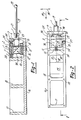
- a touch probe arranged in accordance with the principles of the invention has substantially rectangular elongate probe housing 16 divided internally into three cavities or compartments 10, 18 and 17.
- Cavity 10 houses the probe detector switch and stylus mounting apparatus.
- Cavity 18 houses the probe detector and telemetry circuitry 23, while cavity 17 holds the probe batteries for supplying operating power to the circuitry in housing cavity 18.
- Circuitry 23 accepts a signal from the sensor mechanism to be described below on input 32 and converts the signal for appropriate transmission via radiated telemetry to a remote receiver associated with the machine tool system utilizing the touch probe.
- the details of such circuitry 23 are not necessary to an understanding of this invention and are therefore not set forth in detail in this description. Examples of known arrangements suitable for use as circuitry 23 are set forth in U.S. Patent Number 4,401,945 - Juengel, issued August 30, 1983, pending U.S. Patent Application Serial Number 478,906 - 3uengel, filed March 25, 1983, pending U.S. Patent Application Serial Number 501,994 - Manns, et al., filed June 14, 1983, and pending U.S. Patent Application Serial Number 504,137 - Juengel, filed June 14, 1983, all assigned to the same assignee as the instant invention.
- the probe stylus movement sensing apparatus is contained in housing cavity 10.
- Mounting base or support block 13 is rigidly coupled to housing 16 via bolt 26 at a first side of cavity 10 extending normally to an end wall of the housing.
- a planar reed spring 8 which is resiliently deformable except in its major plane, has a first side coupled to support block 13 via reed clamp 14 and two screws 15.
- first and second wire springs 9a and 9b are resiliently flexible except along their longitudinal axes.
- stylus holder 1 Attached to the opposite ends of reed spring 8 and wire springs 9a, 9b is a stylus holder 1, which is movable relative to probe housing 16.
- Reed spring 8 is coupled to stylus holder via reed spring clamp 2 and two additional screws 15.
- Wire springs 9a, 9b are coupled to stylus holder 1 via wire spring clamp I engaging the ends of the other two screws 15.
- a second portion of stylus holder 1 protrudes through a central aperture in reed spring 8 and in aperture 25 in the end wall of probe housing 16.
- the protruding portion of stylus holder 1 has a threaded bore 22 for coupling receipt of a threaded end 21 of replaceable stylus 19 having a suitably shaped contact tip portion 20.
- Contact strip 6 is electrically isolated from housing strip 16 by an adhesive non-conductive bonding strip 7.
- Contact strip 6 is positioned such that it extends along a dimension perpendicular or normal, to the common longitudinal axis 300 shared by housing 16, apperture 25 and the protruding portion of stylus holder 1.
- Mounted to the first portion of stylus holder 1 are substantially spherically shaped contacts 5a and 5b held respectively in contact holders, or cups, 3a and 3b.
- Contacts 5a and 5b are preferably fashioned from cemented tungsten carbide.
- contacts 5a and 5b abut contact strip 6 in point contact fashion, thereby defining a linear dimension passing through the two point contacts which is normal to axis 300, parallel to the non-deformable plane of reed spring 8, and normal to the longitudinal axis of wire springs 9a and 9b.
- the combination of the reed spring 8 and wire springs 9a and 9b operates to restrict the movement of stylus holder 1 (and therefore movement of stylus 19) to either linear movement parallel to axis 300 (as shown by direction 35 in Fig. 2) or pivotal movement in planes paralled to both axis 300 and to the linear dimension defined by the point contacts between contacts 5a, 5b and contact strip 6 (i.e. the stylus tip can pivot generally in the direction 34 shown in Fig. 2).
- biasing coil spring 24 may be interposed between a rearward housing wall of cavity 10 and the first portion of stylus holder 1.
- bias spring 24 could be replaced by the resilient action of a metal bellows (not shown) which would be coupled between the protruding portion of stylus holder 1 and the perimeter of housing aperture 25.
- a further adjustment feature is provided by screw 27 threadingly engaging a bore in housing 16 running normal to axis 300 and placed so that an inner end of screw 27 engages stylus holder 1.
- screw 27 threadingly engaging a bore in housing 16 running normal to axis 300 and placed so that an inner end of screw 27 engages stylus holder 1.
- holder 1 will pivot in the allowed plane of pivotal motion to differentially alter the pre-load force between contacts 5a, 5b and contact strip 6 in the stylus holder rest position.
- the pre-travel required to leave the rest position by stylus movement can be adjusted to compensate for a stylus that is slightly off center - i.e. having a longitudinal axis not in alignment with axis 300.
- An electrical signal indicative of stylus movement from the probe rest position can be generated with the following arrangement.
- Contact 5b is grounded to housing 16 via electrically conductive mounting cup 3b, spring clamp 2, reed spring 8, and mounting base 13.
- Contact 5a is electrically isolated from grounded housing 16 via insulated contact mounting cup 3a and is coupled to output terminal 31 via conductor 4 which passes through conduit 28 in reed clamp 2, conduit 29 in stylus holder 1 and conduit 30 in the rear housing wall of cavity 10.
- a simple series circuit in the probe rest position extends from electrical ground through contact 5b, through contact strip 6 (which, as previously mentioned, is electrically isolated from housing 16 by strip 7), through contact 5a to output terminal 31 via conductor 4.
Landscapes
- Physics & Mathematics (AREA)
- General Physics & Mathematics (AREA)
- Measurement Of Length, Angles, Or The Like Using Electric Or Magnetic Means (AREA)
- Length Measuring Devices With Unspecified Measuring Means (AREA)
- A Measuring Device Byusing Mechanical Method (AREA)
Applications Claiming Priority (2)
| Application Number | Priority Date | Filing Date | Title |
|---|---|---|---|
| US06/593,506 US4542590A (en) | 1984-03-26 | 1984-03-26 | Two axis touch probe |
| US593506 | 1984-03-26 |
Publications (2)
| Publication Number | Publication Date |
|---|---|
| EP0162233A1 true EP0162233A1 (de) | 1985-11-27 |
| EP0162233B1 EP0162233B1 (de) | 1988-09-28 |
Family
ID=24374985
Family Applications (1)
| Application Number | Title | Priority Date | Filing Date |
|---|---|---|---|
| EP85103604A Expired EP0162233B1 (de) | 1984-03-26 | 1985-03-26 | Zweiachsiger Taster |
Country Status (6)
| Country | Link |
|---|---|
| US (1) | US4542590A (de) |
| EP (1) | EP0162233B1 (de) |
| JP (1) | JPS6122204A (de) |
| CA (1) | CA1216338A (de) |
| DE (1) | DE3565314D1 (de) |
| ZA (1) | ZA852046B (de) |
Families Citing this family (7)
| Publication number | Priority date | Publication date | Assignee | Title |
|---|---|---|---|---|
| DE3532184C1 (de) * | 1985-09-10 | 1987-02-19 | Zeiss Carl Fa | Kollisionsschutz fuer den Tastkopf einer Messmaschine |
| JPH0634645Y2 (ja) * | 1986-07-17 | 1994-09-07 | 株式会社メトロ−ル | 二次元タツチセンサ |
| US4956923A (en) * | 1989-11-06 | 1990-09-18 | The Micromanipulator Co., Inc. | Probe assembly including touchdown sensor |
| US5109610A (en) * | 1991-04-23 | 1992-05-05 | Johnson James D | True position probe |
| USD648504S1 (en) * | 2010-12-22 | 2011-11-08 | Funeral Products B.V. | Heart shaped urn |
| USD833104S1 (en) * | 2017-02-06 | 2018-11-06 | Infinityurns, Llc | Urn |
| USD1000749S1 (en) | 2021-11-01 | 2023-10-03 | Infinityurns, Llc | Curved heart cremation urn |
Citations (5)
| Publication number | Priority date | Publication date | Assignee | Title |
|---|---|---|---|---|
| CH594230A5 (de) * | 1973-06-14 | 1977-12-30 | Rolls Royce 1971 Ltd | |
| US4136458A (en) * | 1976-10-01 | 1979-01-30 | The Bendix Corporation | Bi-axial probe |
| GB2070249A (en) * | 1980-02-21 | 1981-09-03 | Rank Organisation Ltd | Contact-sensitive probe |
| US4397093A (en) * | 1976-12-24 | 1983-08-09 | Rolls Royce Limited | Probe for use in measuring apparatus |
| DE3321454A1 (de) * | 1982-06-14 | 1983-12-15 | The Valeron Corp., 48084 Troy, Mich. | Tastfuehler |
Family Cites Families (3)
| Publication number | Priority date | Publication date | Assignee | Title |
|---|---|---|---|---|
| US3122970A (en) * | 1964-03-03 | Certificate of correction | ||
| US3766653A (en) * | 1971-10-04 | 1973-10-23 | Lockheed Missiles Space | Three axis inspection probe |
| JPS5491693A (en) * | 1977-12-28 | 1979-07-20 | Nippon Steel Corp | Positioning control system of moving body |
-
1984
- 1984-03-26 US US06/593,506 patent/US4542590A/en not_active Expired - Fee Related
-
1985
- 1985-03-18 CA CA000476781A patent/CA1216338A/en not_active Expired
- 1985-03-19 ZA ZA852046A patent/ZA852046B/xx unknown
- 1985-03-26 DE DE8585103604T patent/DE3565314D1/de not_active Expired
- 1985-03-26 EP EP85103604A patent/EP0162233B1/de not_active Expired
- 1985-03-26 JP JP60061750A patent/JPS6122204A/ja active Pending
Patent Citations (6)
| Publication number | Priority date | Publication date | Assignee | Title |
|---|---|---|---|---|
| CH594230A5 (de) * | 1973-06-14 | 1977-12-30 | Rolls Royce 1971 Ltd | |
| US4136458A (en) * | 1976-10-01 | 1979-01-30 | The Bendix Corporation | Bi-axial probe |
| US4136458B1 (de) * | 1976-10-01 | 1989-07-04 | Renishaw Plc | |
| US4397093A (en) * | 1976-12-24 | 1983-08-09 | Rolls Royce Limited | Probe for use in measuring apparatus |
| GB2070249A (en) * | 1980-02-21 | 1981-09-03 | Rank Organisation Ltd | Contact-sensitive probe |
| DE3321454A1 (de) * | 1982-06-14 | 1983-12-15 | The Valeron Corp., 48084 Troy, Mich. | Tastfuehler |
Also Published As
| Publication number | Publication date |
|---|---|
| JPS6122204A (ja) | 1986-01-30 |
| EP0162233B1 (de) | 1988-09-28 |
| DE3565314D1 (en) | 1988-11-03 |
| US4542590A (en) | 1985-09-24 |
| ZA852046B (en) | 1985-11-27 |
| CA1216338A (en) | 1987-01-06 |
Similar Documents
| Publication | Publication Date | Title |
|---|---|---|
| US4451987A (en) | Touch probe | |
| EP0269795B1 (de) | Vorrichtung zum Bestimmen der Lage der Oberflächen eines festen Objektes | |
| US4443946A (en) | Probe for measuring workpieces | |
| GB1593682A (en) | Probe for use in mearusing apparatus | |
| US4625417A (en) | Probe with stylus pressure adjustment | |
| WO1986003829A1 (en) | Contact-sensing probe | |
| US4542590A (en) | Two axis touch probe | |
| US4765181A (en) | Surface texture measuring instrument | |
| JP2003207330A (ja) | トリガプローブおよびトリガプローブの組立て方法 | |
| JPH0617766B2 (ja) | タッチ信号プロ−ブ | |
| CN213657705U (zh) | 精密检测装置、刀具辅件和机械加工系统 | |
| US4523063A (en) | Touch probe having nonconductive contact carriers | |
| CN213579023U (zh) | 精密检测装置、刀具辅件和机械加工系统 | |
| US4553001A (en) | Touch probe having nonconductive contact carriers | |
| CN213579024U (zh) | 精密检测装置、刀具辅件和机械加工系统 | |
| CN110108183A (zh) | 精密检测装置、刀具辅件及其制造方法 | |
| JPH0239205Y2 (de) | ||
| CN109945759A (zh) | 精密检测装置、刀具辅件和机械加工系统 | |
| US5594995A (en) | Touch sensor | |
| CN210173126U (zh) | 刀具辅件 | |
| US5584200A (en) | Universal crimping tool locator | |
| EP0768510B1 (de) | Berührungssensor | |
| CN109945760A (zh) | 精密检测装置、刀具辅件和机械加工系统 | |
| EP0852327B1 (de) | Berührungssensor | |
| JP2958477B2 (ja) | タッチセンサ |
Legal Events
| Date | Code | Title | Description |
|---|---|---|---|
| PUAI | Public reference made under article 153(3) epc to a published international application that has entered the european phase |
Free format text: ORIGINAL CODE: 0009012 |
|
| AK | Designated contracting states |
Designated state(s): BE DE FR GB IT NL SE |
|
| 17P | Request for examination filed |
Effective date: 19860116 |
|
| 17Q | First examination report despatched |
Effective date: 19870525 |
|
| GRAA | (expected) grant |
Free format text: ORIGINAL CODE: 0009210 |
|
| AK | Designated contracting states |
Kind code of ref document: B1 Designated state(s): BE DE FR GB IT NL SE |
|
| RAP1 | Party data changed (applicant data changed or rights of an application transferred) |
Owner name: GTE VALENITE CORPORATION |
|
| REF | Corresponds to: |
Ref document number: 3565314 Country of ref document: DE Date of ref document: 19881103 |
|
| ET | Fr: translation filed | ||
| ITF | It: translation for a ep patent filed | ||
| PLBE | No opposition filed within time limit |
Free format text: ORIGINAL CODE: 0009261 |
|
| STAA | Information on the status of an ep patent application or granted ep patent |
Free format text: STATUS: NO OPPOSITION FILED WITHIN TIME LIMIT |
|
| 26N | No opposition filed | ||
| PGFP | Annual fee paid to national office [announced via postgrant information from national office to epo] |
Ref country code: SE Payment date: 19900227 Year of fee payment: 6 |
|
| PGFP | Annual fee paid to national office [announced via postgrant information from national office to epo] |
Ref country code: FR Payment date: 19900301 Year of fee payment: 6 Ref country code: DE Payment date: 19900301 Year of fee payment: 6 |
|
| PGFP | Annual fee paid to national office [announced via postgrant information from national office to epo] |
Ref country code: BE Payment date: 19900308 Year of fee payment: 6 |
|
| ITTA | It: last paid annual fee | ||
| PGFP | Annual fee paid to national office [announced via postgrant information from national office to epo] |
Ref country code: NL Payment date: 19900331 Year of fee payment: 6 Ref country code: GB Payment date: 19900331 Year of fee payment: 6 |
|
| PG25 | Lapsed in a contracting state [announced via postgrant information from national office to epo] |
Ref country code: GB Effective date: 19910326 |
|
| PG25 | Lapsed in a contracting state [announced via postgrant information from national office to epo] |
Ref country code: SE Effective date: 19910327 |
|
| PG25 | Lapsed in a contracting state [announced via postgrant information from national office to epo] |
Ref country code: BE Effective date: 19910331 |
|
| BERE | Be: lapsed |
Owner name: GTE VALENITE CORP. Effective date: 19910331 |
|
| PG25 | Lapsed in a contracting state [announced via postgrant information from national office to epo] |
Ref country code: NL Effective date: 19911001 |
|
| NLV4 | Nl: lapsed or anulled due to non-payment of the annual fee | ||
| GBPC | Gb: european patent ceased through non-payment of renewal fee | ||
| PG25 | Lapsed in a contracting state [announced via postgrant information from national office to epo] |
Ref country code: FR Effective date: 19911129 |
|
| PG25 | Lapsed in a contracting state [announced via postgrant information from national office to epo] |
Ref country code: DE Effective date: 19920101 |
|
| REG | Reference to a national code |
Ref country code: FR Ref legal event code: ST |
|
| EUG | Se: european patent has lapsed |
Ref document number: 85103604.6 Effective date: 19911009 |