EP0161824A1 - System zum Einstellen des Übersetzungsverhältnisses eines stufenlosen Getriebes - Google Patents
System zum Einstellen des Übersetzungsverhältnisses eines stufenlosen Getriebes Download PDFInfo
- Publication number
- EP0161824A1 EP0161824A1 EP85302736A EP85302736A EP0161824A1 EP 0161824 A1 EP0161824 A1 EP 0161824A1 EP 85302736 A EP85302736 A EP 85302736A EP 85302736 A EP85302736 A EP 85302736A EP 0161824 A1 EP0161824 A1 EP 0161824A1
- Authority
- EP
- European Patent Office
- Prior art keywords
- disc
- transmission ratio
- transmission
- signal
- engine
- Prior art date
- Legal status (The legal status is an assumption and is not a legal conclusion. Google has not performed a legal analysis and makes no representation as to the accuracy of the status listed.)
- Granted
Links
- 230000005540 biological transmission Effects 0.000 title claims abstract description 58
- 230000001052 transient effect Effects 0.000 claims description 4
- 230000001133 acceleration Effects 0.000 claims description 2
- 230000000063 preceeding effect Effects 0.000 claims 1
- 239000000843 powder Substances 0.000 description 9
- 230000001419 dependent effect Effects 0.000 description 6
- 238000007493 shaping process Methods 0.000 description 4
- 238000010586 diagram Methods 0.000 description 3
- 230000004907 flux Effects 0.000 description 2
- 238000010276 construction Methods 0.000 description 1
- 230000007423 decrease Effects 0.000 description 1
- 230000000994 depressogenic effect Effects 0.000 description 1
- 239000000696 magnetic material Substances 0.000 description 1
- 239000006247 magnetic powder Substances 0.000 description 1
- 230000007935 neutral effect Effects 0.000 description 1
Images


Classifications
-
- F—MECHANICAL ENGINEERING; LIGHTING; HEATING; WEAPONS; BLASTING
- F16—ENGINEERING ELEMENTS AND UNITS; GENERAL MEASURES FOR PRODUCING AND MAINTAINING EFFECTIVE FUNCTIONING OF MACHINES OR INSTALLATIONS; THERMAL INSULATION IN GENERAL
- F16H—GEARING
- F16H61/00—Control functions within control units of change-speed- or reversing-gearings for conveying rotary motion ; Control of exclusively fluid gearing, friction gearing, gearings with endless flexible members or other particular types of gearing
- F16H61/66—Control functions within control units of change-speed- or reversing-gearings for conveying rotary motion ; Control of exclusively fluid gearing, friction gearing, gearings with endless flexible members or other particular types of gearing specially adapted for continuously variable gearings
-
- B—PERFORMING OPERATIONS; TRANSPORTING
- B60—VEHICLES IN GENERAL
- B60W—CONJOINT CONTROL OF VEHICLE SUB-UNITS OF DIFFERENT TYPE OR DIFFERENT FUNCTION; CONTROL SYSTEMS SPECIALLY ADAPTED FOR HYBRID VEHICLES; ROAD VEHICLE DRIVE CONTROL SYSTEMS FOR PURPOSES NOT RELATED TO THE CONTROL OF A PARTICULAR SUB-UNIT
- B60W10/00—Conjoint control of vehicle sub-units of different type or different function
- B60W10/02—Conjoint control of vehicle sub-units of different type or different function including control of driveline clutches
-
- B—PERFORMING OPERATIONS; TRANSPORTING
- B60—VEHICLES IN GENERAL
- B60W—CONJOINT CONTROL OF VEHICLE SUB-UNITS OF DIFFERENT TYPE OR DIFFERENT FUNCTION; CONTROL SYSTEMS SPECIALLY ADAPTED FOR HYBRID VEHICLES; ROAD VEHICLE DRIVE CONTROL SYSTEMS FOR PURPOSES NOT RELATED TO THE CONTROL OF A PARTICULAR SUB-UNIT
- B60W10/00—Conjoint control of vehicle sub-units of different type or different function
- B60W10/04—Conjoint control of vehicle sub-units of different type or different function including control of propulsion units
- B60W10/06—Conjoint control of vehicle sub-units of different type or different function including control of propulsion units including control of combustion engines
-
- B—PERFORMING OPERATIONS; TRANSPORTING
- B60—VEHICLES IN GENERAL
- B60W—CONJOINT CONTROL OF VEHICLE SUB-UNITS OF DIFFERENT TYPE OR DIFFERENT FUNCTION; CONTROL SYSTEMS SPECIALLY ADAPTED FOR HYBRID VEHICLES; ROAD VEHICLE DRIVE CONTROL SYSTEMS FOR PURPOSES NOT RELATED TO THE CONTROL OF A PARTICULAR SUB-UNIT
- B60W10/00—Conjoint control of vehicle sub-units of different type or different function
- B60W10/10—Conjoint control of vehicle sub-units of different type or different function including control of change-speed gearings
- B60W10/101—Infinitely variable gearings
- B60W10/107—Infinitely variable gearings with endless flexible members
-
- F—MECHANICAL ENGINEERING; LIGHTING; HEATING; WEAPONS; BLASTING
- F16—ENGINEERING ELEMENTS AND UNITS; GENERAL MEASURES FOR PRODUCING AND MAINTAINING EFFECTIVE FUNCTIONING OF MACHINES OR INSTALLATIONS; THERMAL INSULATION IN GENERAL
- F16D—COUPLINGS FOR TRANSMITTING ROTATION; CLUTCHES; BRAKES
- F16D48/00—External control of clutches
- F16D48/06—Control by electric or electronic means, e.g. of fluid pressure
- F16D48/064—Control of electrically or electromagnetically actuated clutches
-
- F—MECHANICAL ENGINEERING; LIGHTING; HEATING; WEAPONS; BLASTING
- F16—ENGINEERING ELEMENTS AND UNITS; GENERAL MEASURES FOR PRODUCING AND MAINTAINING EFFECTIVE FUNCTIONING OF MACHINES OR INSTALLATIONS; THERMAL INSULATION IN GENERAL
- F16D—COUPLINGS FOR TRANSMITTING ROTATION; CLUTCHES; BRAKES
- F16D48/00—External control of clutches
- F16D48/06—Control by electric or electronic means, e.g. of fluid pressure
- F16D48/066—Control of fluid pressure, e.g. using an accumulator
-
- F—MECHANICAL ENGINEERING; LIGHTING; HEATING; WEAPONS; BLASTING
- F16—ENGINEERING ELEMENTS AND UNITS; GENERAL MEASURES FOR PRODUCING AND MAINTAINING EFFECTIVE FUNCTIONING OF MACHINES OR INSTALLATIONS; THERMAL INSULATION IN GENERAL
- F16H—GEARING
- F16H61/00—Control functions within control units of change-speed- or reversing-gearings for conveying rotary motion ; Control of exclusively fluid gearing, friction gearing, gearings with endless flexible members or other particular types of gearing
- F16H61/66—Control functions within control units of change-speed- or reversing-gearings for conveying rotary motion ; Control of exclusively fluid gearing, friction gearing, gearings with endless flexible members or other particular types of gearing specially adapted for continuously variable gearings
- F16H61/662—Control functions within control units of change-speed- or reversing-gearings for conveying rotary motion ; Control of exclusively fluid gearing, friction gearing, gearings with endless flexible members or other particular types of gearing specially adapted for continuously variable gearings with endless flexible members
- F16H61/66254—Control functions within control units of change-speed- or reversing-gearings for conveying rotary motion ; Control of exclusively fluid gearing, friction gearing, gearings with endless flexible members or other particular types of gearing specially adapted for continuously variable gearings with endless flexible members controlling of shifting being influenced by a signal derived from the engine and the main coupling
- F16H61/66259—Control functions within control units of change-speed- or reversing-gearings for conveying rotary motion ; Control of exclusively fluid gearing, friction gearing, gearings with endless flexible members or other particular types of gearing specially adapted for continuously variable gearings with endless flexible members controlling of shifting being influenced by a signal derived from the engine and the main coupling using electrical or electronical sensing or control means
-
- F—MECHANICAL ENGINEERING; LIGHTING; HEATING; WEAPONS; BLASTING
- F16—ENGINEERING ELEMENTS AND UNITS; GENERAL MEASURES FOR PRODUCING AND MAINTAINING EFFECTIVE FUNCTIONING OF MACHINES OR INSTALLATIONS; THERMAL INSULATION IN GENERAL
- F16D—COUPLINGS FOR TRANSMITTING ROTATION; CLUTCHES; BRAKES
- F16D2500/00—External control of clutches by electric or electronic means
- F16D2500/10—System to be controlled
- F16D2500/102—Actuator
- F16D2500/1021—Electrical type
- F16D2500/1022—Electromagnet
-
- F—MECHANICAL ENGINEERING; LIGHTING; HEATING; WEAPONS; BLASTING
- F16—ENGINEERING ELEMENTS AND UNITS; GENERAL MEASURES FOR PRODUCING AND MAINTAINING EFFECTIVE FUNCTIONING OF MACHINES OR INSTALLATIONS; THERMAL INSULATION IN GENERAL
- F16D—COUPLINGS FOR TRANSMITTING ROTATION; CLUTCHES; BRAKES
- F16D2500/00—External control of clutches by electric or electronic means
- F16D2500/10—System to be controlled
- F16D2500/102—Actuator
- F16D2500/1026—Hydraulic
-
- F—MECHANICAL ENGINEERING; LIGHTING; HEATING; WEAPONS; BLASTING
- F16—ENGINEERING ELEMENTS AND UNITS; GENERAL MEASURES FOR PRODUCING AND MAINTAINING EFFECTIVE FUNCTIONING OF MACHINES OR INSTALLATIONS; THERMAL INSULATION IN GENERAL
- F16D—COUPLINGS FOR TRANSMITTING ROTATION; CLUTCHES; BRAKES
- F16D2500/00—External control of clutches by electric or electronic means
- F16D2500/10—System to be controlled
- F16D2500/104—Clutch
- F16D2500/10406—Clutch position
- F16D2500/10412—Transmission line of a vehicle
-
- F—MECHANICAL ENGINEERING; LIGHTING; HEATING; WEAPONS; BLASTING
- F16—ENGINEERING ELEMENTS AND UNITS; GENERAL MEASURES FOR PRODUCING AND MAINTAINING EFFECTIVE FUNCTIONING OF MACHINES OR INSTALLATIONS; THERMAL INSULATION IN GENERAL
- F16D—COUPLINGS FOR TRANSMITTING ROTATION; CLUTCHES; BRAKES
- F16D2500/00—External control of clutches by electric or electronic means
- F16D2500/10—System to be controlled
- F16D2500/108—Gear
- F16D2500/1088—CVT
-
- F—MECHANICAL ENGINEERING; LIGHTING; HEATING; WEAPONS; BLASTING
- F16—ENGINEERING ELEMENTS AND UNITS; GENERAL MEASURES FOR PRODUCING AND MAINTAINING EFFECTIVE FUNCTIONING OF MACHINES OR INSTALLATIONS; THERMAL INSULATION IN GENERAL
- F16D—COUPLINGS FOR TRANSMITTING ROTATION; CLUTCHES; BRAKES
- F16D2500/00—External control of clutches by electric or electronic means
- F16D2500/30—Signal inputs
- F16D2500/302—Signal inputs from the actuator
- F16D2500/3021—Angle
-
- F—MECHANICAL ENGINEERING; LIGHTING; HEATING; WEAPONS; BLASTING
- F16—ENGINEERING ELEMENTS AND UNITS; GENERAL MEASURES FOR PRODUCING AND MAINTAINING EFFECTIVE FUNCTIONING OF MACHINES OR INSTALLATIONS; THERMAL INSULATION IN GENERAL
- F16D—COUPLINGS FOR TRANSMITTING ROTATION; CLUTCHES; BRAKES
- F16D2500/00—External control of clutches by electric or electronic means
- F16D2500/30—Signal inputs
- F16D2500/305—Signal inputs from the clutch cooling
- F16D2500/3055—Cooling oil properties
- F16D2500/3058—Cooling oil pressure
-
- F—MECHANICAL ENGINEERING; LIGHTING; HEATING; WEAPONS; BLASTING
- F16—ENGINEERING ELEMENTS AND UNITS; GENERAL MEASURES FOR PRODUCING AND MAINTAINING EFFECTIVE FUNCTIONING OF MACHINES OR INSTALLATIONS; THERMAL INSULATION IN GENERAL
- F16D—COUPLINGS FOR TRANSMITTING ROTATION; CLUTCHES; BRAKES
- F16D2500/00—External control of clutches by electric or electronic means
- F16D2500/30—Signal inputs
- F16D2500/306—Signal inputs from the engine
- F16D2500/3067—Speed of the engine
-
- F—MECHANICAL ENGINEERING; LIGHTING; HEATING; WEAPONS; BLASTING
- F16—ENGINEERING ELEMENTS AND UNITS; GENERAL MEASURES FOR PRODUCING AND MAINTAINING EFFECTIVE FUNCTIONING OF MACHINES OR INSTALLATIONS; THERMAL INSULATION IN GENERAL
- F16D—COUPLINGS FOR TRANSMITTING ROTATION; CLUTCHES; BRAKES
- F16D2500/00—External control of clutches by electric or electronic means
- F16D2500/30—Signal inputs
- F16D2500/308—Signal inputs from the transmission
- F16D2500/3081—Signal inputs from the transmission from the input shaft
- F16D2500/30816—Speed of the input shaft
-
- F—MECHANICAL ENGINEERING; LIGHTING; HEATING; WEAPONS; BLASTING
- F16—ENGINEERING ELEMENTS AND UNITS; GENERAL MEASURES FOR PRODUCING AND MAINTAINING EFFECTIVE FUNCTIONING OF MACHINES OR INSTALLATIONS; THERMAL INSULATION IN GENERAL
- F16D—COUPLINGS FOR TRANSMITTING ROTATION; CLUTCHES; BRAKES
- F16D2500/00—External control of clutches by electric or electronic means
- F16D2500/30—Signal inputs
- F16D2500/308—Signal inputs from the transmission
- F16D2500/3082—Signal inputs from the transmission from the output shaft
- F16D2500/30825—Speed of the output shaft
-
- F—MECHANICAL ENGINEERING; LIGHTING; HEATING; WEAPONS; BLASTING
- F16—ENGINEERING ELEMENTS AND UNITS; GENERAL MEASURES FOR PRODUCING AND MAINTAINING EFFECTIVE FUNCTIONING OF MACHINES OR INSTALLATIONS; THERMAL INSULATION IN GENERAL
- F16D—COUPLINGS FOR TRANSMITTING ROTATION; CLUTCHES; BRAKES
- F16D2500/00—External control of clutches by electric or electronic means
- F16D2500/70—Details about the implementation of the control system
- F16D2500/702—Look-up tables
- F16D2500/70205—Clutch actuator
- F16D2500/70223—Current
-
- F—MECHANICAL ENGINEERING; LIGHTING; HEATING; WEAPONS; BLASTING
- F16—ENGINEERING ELEMENTS AND UNITS; GENERAL MEASURES FOR PRODUCING AND MAINTAINING EFFECTIVE FUNCTIONING OF MACHINES OR INSTALLATIONS; THERMAL INSULATION IN GENERAL
- F16D—COUPLINGS FOR TRANSMITTING ROTATION; CLUTCHES; BRAKES
- F16D2500/00—External control of clutches by electric or electronic means
- F16D2500/70—Details about the implementation of the control system
- F16D2500/702—Look-up tables
- F16D2500/70205—Clutch actuator
- F16D2500/70241—Angle
-
- F—MECHANICAL ENGINEERING; LIGHTING; HEATING; WEAPONS; BLASTING
- F16—ENGINEERING ELEMENTS AND UNITS; GENERAL MEASURES FOR PRODUCING AND MAINTAINING EFFECTIVE FUNCTIONING OF MACHINES OR INSTALLATIONS; THERMAL INSULATION IN GENERAL
- F16D—COUPLINGS FOR TRANSMITTING ROTATION; CLUTCHES; BRAKES
- F16D2500/00—External control of clutches by electric or electronic means
- F16D2500/70—Details about the implementation of the control system
- F16D2500/702—Look-up tables
- F16D2500/70252—Clutch torque
- F16D2500/7027—Engine speed
-
- F—MECHANICAL ENGINEERING; LIGHTING; HEATING; WEAPONS; BLASTING
- F16—ENGINEERING ELEMENTS AND UNITS; GENERAL MEASURES FOR PRODUCING AND MAINTAINING EFFECTIVE FUNCTIONING OF MACHINES OR INSTALLATIONS; THERMAL INSULATION IN GENERAL
- F16D—COUPLINGS FOR TRANSMITTING ROTATION; CLUTCHES; BRAKES
- F16D2500/00—External control of clutches by electric or electronic means
- F16D2500/70—Details about the implementation of the control system
- F16D2500/704—Output parameters from the control unit; Target parameters to be controlled
- F16D2500/70402—Actuator parameters
- F16D2500/7041—Position
-
- F—MECHANICAL ENGINEERING; LIGHTING; HEATING; WEAPONS; BLASTING
- F16—ENGINEERING ELEMENTS AND UNITS; GENERAL MEASURES FOR PRODUCING AND MAINTAINING EFFECTIVE FUNCTIONING OF MACHINES OR INSTALLATIONS; THERMAL INSULATION IN GENERAL
- F16D—COUPLINGS FOR TRANSMITTING ROTATION; CLUTCHES; BRAKES
- F16D2500/00—External control of clutches by electric or electronic means
- F16D2500/70—Details about the implementation of the control system
- F16D2500/704—Output parameters from the control unit; Target parameters to be controlled
- F16D2500/70464—Transmission parameters
- F16D2500/70488—Selection of the gear ratio
-
- F—MECHANICAL ENGINEERING; LIGHTING; HEATING; WEAPONS; BLASTING
- F16—ENGINEERING ELEMENTS AND UNITS; GENERAL MEASURES FOR PRODUCING AND MAINTAINING EFFECTIVE FUNCTIONING OF MACHINES OR INSTALLATIONS; THERMAL INSULATION IN GENERAL
- F16D—COUPLINGS FOR TRANSMITTING ROTATION; CLUTCHES; BRAKES
- F16D2500/00—External control of clutches by electric or electronic means
- F16D2500/70—Details about the implementation of the control system
- F16D2500/706—Strategy of control
- F16D2500/70668—Signal filtering
-
- F—MECHANICAL ENGINEERING; LIGHTING; HEATING; WEAPONS; BLASTING
- F16—ENGINEERING ELEMENTS AND UNITS; GENERAL MEASURES FOR PRODUCING AND MAINTAINING EFFECTIVE FUNCTIONING OF MACHINES OR INSTALLATIONS; THERMAL INSULATION IN GENERAL
- F16D—COUPLINGS FOR TRANSMITTING ROTATION; CLUTCHES; BRAKES
- F16D2500/00—External control of clutches by electric or electronic means
- F16D2500/70—Details about the implementation of the control system
- F16D2500/71—Actions
- F16D2500/7107—Others
- F16D2500/7109—Pulsed signal; Generating or processing pulsed signals; PWM, width modulation, frequency or amplitude modulation
Definitions
- the present invention relates to a system for controlling the transmission ratio of an infinitely variable transmission for a vehicle.
- a known infinitely variable belt-drive transmission includes an endless belt running over a primary pulley and a secondary pulley.
- Each pulley comprises a movable conical disc which is axially moved by a pressure oil servo device so as to vary the running diameter of the belt on the pulley depending on driving conditions.
- the system is provided with an oil pressure regulator valve and a transmission ratio control valve, each valve having a spool which shifts to control pressure of oil.
- the primary pulley has a pitot pressure generating device for producing Pitot pressure dependent on engine speed.
- the pitot pressure is applied to one side of the spool of each valve to urge that spool.
- the actual transmission ratio is detected by the axial position of the movable conical disc of the primary pulley, which represents the running diameter of the belt on the primary pulley.
- the position of the movable conical disc is transmitted as a pressure quantity to the other side of the spool of the pressure regulator valve. Further, the intake manifold pressure of the engine is applied to the other side of the spool of the transmission ratio control valve through a vacuum operated actuator so as to control the transmission ratio. Since the conventional control system comprises various mechanical devices, the construction is very complicated. In addition, the Pitot pressure increases as a curve of second degree with increasing engine speed. Accordingly, it is difficult to control the transmission ratio exactly at low engine speeds. Further, the intake manifold pressure also changes as a curve of second degree, with the change of opening degree of a throttle valve of the engine. Therefore, the control operation at high engine speed can not be properly controlled. In addition, characteristics of signals representing engine speed, manifold vacuum and pulley transmission ratio are roughly decided in accordance with engine operating conditions and cannot be corrected in dependence on various driving conditions of a vehicle.
- a system for controlling the transmission ratio of an infinitely variable transmission for an engine mounted in a vehicle, the engine having a throttle valve, and being connectable through a clutch to the transmission which includes a belt drive unit which has a primary pulley having a hydraulically shiftable disc and a hydraulic cylinder for operating the disc, a secondary pulley having a hydraulically shiftable disc and a hydraulic cylinder for operating the disc, and a belt engaged with both pulleys
- the system comprising: a hydraulic circuit having a transmission ratio control valve operable by a supply of oil for selectively shifting the disc of the primary pulley in a downshift direction or upshift direction; first means for detecting a transient condition at acceleration of the vehicle and for producing a first signal; second means responsive to the first signal for producing a second signal representing the variation rate of the transient; and third means responsive to the first and second signals for operating the transmission ratio control valve, so that in use the disc of the primary pulley will be shifted in the downshift direction when the vehicle accelerate
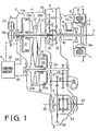
- an infinitely variable belt-drive automatic transmission assembly for a vehicle comprises an electromagnetic powder clutch 1, a belt drive transmission including a selector device 3, and a belt drive unit 2 having pulleys and belt deivce 4, a final reduction device 5, and a pressure oil control section 6.
- a crankshaft 7 of an engine (not shown) is connected to an annular drive member 9 through a drive plate 9a of the electromagnetic powder clutch 1.
- the electromagnetic powder clutch comprises a driven member 11, a magnetizing coil 8 provided in the drive member 9.
- the driven member 11 has its outer periphery spaced from the inner periphery of the drive member 9 by a gap 12, and a powder chamber 13 is defined between the drive member 9 and driven member 11.
- the powder chamber 13 is filled with powder of magnetic material.
- the driven member 11 is secured to an input shaft 10 of the belt-drive transmission.
- a holder 14 secured to the drive member 9 carries slip rings 15 which are electrically connected to the coil 8.
- the coil 8 is supplied through brushes 16 and slip rings 15 with current from a control circuit for the electromagnetic powder clutch.
- drive member 9 When the magnetizing coil 8 is excited by clutch current, drive member 9 is magnetized to produce a magnetic flux passing through the drive member 11. The magnetic powder is aggregated in the gap 12 by the magnetic flux and the driven member 11 is engaged with the drive member 9 by the powder. On the other hand, when the clutch current is cut off, the drive and driven members 9 and 11 are disengaged from,one another.
- the selector device 3 is provided between the input shaft 10 and a main shaft 17.
- the main shaft 17 is cylindrical and is disposed coaxially with the input shaft 10.
- the selector device 3 comprises a drive gear 18 integral with input shaft 17, reverse driven gear 19 rotatably mounted on the main shaft 17, and a synchronizer 22 mounted on the main shaft 17.
- the drive gear 18 meshes with one of a counter gear 20.
- Another gear of the counter gear 20 engages with an idler gear 21, which in turn engages with the driven gear 19.
- the synchronizer 22 has a well known mechanism and comprises a hub secured to the main shaft 17, and a synchronizer sleeve slidably engaged to the hub with splines.
- the synchronizer sleeve is adapted to engage with splines of the drive gear 18 or with splines of driven gear 19.
- a neutral position (N range) of a selector lever (not shown) the synchronizer 22 does not engage either gear, so that the main shaft 17 is disconnected from the input shaft 10.
- D range driving position
- the main shaft 17 has an axial passage in which an oil pump driving shaft 36 connected to crankshaft 7 is mounted.
- An output shaft 23 is provided in parallel with the main shaft 17.
- a primary pulley 24 and a secondary pulley 25 are mounted on shafts 17 and 23.
- a fixed conical disc 24b of the primary pulley 24 is integral with main shaft 17 and an axially movable conical disc 24a is axially slidably mounted on the main shaft 17.
- the movable conical disc 24a also slides in a cylinder 27a formed on the main shaft 17 to provide a servo device 27.
- a chamber of the servo device 27 communicates with a gear pump 37 through a pressure oil control circuit 38.
- the gear pump 37 is driven by the shaft 36.
- a fixed conical disc 25b of the secondary pulley 25 is formed on the output shaft 23 opposite the movable disc 24a and a movable conical disc 25a is slidably mounted on the shaft 23 opposite disc 24b.
- Movable conical disc 25a has a cylindrical portion in which a piston portion 28a of the output shaft 23 is slidably engaged to form a servo device 28.
- a chamber of the servo device 28 is communicated with the oil pump 37 through the pressure oil control circuit 38.
- a drive belt 26 engages with the primary pulley 24 and the secondary pulley 25.
- a drive gear 29 Secured to the output shaft 23 is a drive gear 29 which engages with an intermediate reduction gear on an intermediate shaft 30.
- An intermediate gear 31 on the shaft 30 engages with a final gear 32. Rotation of the final gear 32 is transmitted to axles 34 and 35 of the vehicle driving wheels through a differential 33.
- the pressure oil control circuit 38 is responsive to vehicle speed, engine speed and throttle valve position for controlling the pressure oil supply to servo devices 27 and 28 thereby moving discs 24a and 25a. Thus, transmission ratio is infinitely changed.
- a chamber 27b of servo device 27 is supplied with pressurized oil by the gear pump 37 from an oil reservoir 42 passing through a filter 41, conduit 39, pressurized regulator valve 67 and transmission ratio control valve 44.
- a chamber 28b of servo device 28 is supplied with pressurized oil through a conduit 40 without passing through valves 67 and 44.
- the movable conical disc 24a is so designed that pressure receiving area thereof is larger than that of movable conical disc 25a.
- the pressure regulator valve 67 has a spool 68, end chamber 69 and a spring 70 provided opposite the end chamber.
- the spring 70 urges the spool 68 to the left to communicate a port 67a with a line pressure supply port 67b and the pressure of the oil supplied to the chamber 69 urges the spool 68 to the right to communicate the port 67b with a drain port 67c, so as to regulate the line pressure in passages 39, 39a.
- the transmission ratio control valve 44 comprises a spool 46 in a valve body 45, chamber 47 and spring 48 opposite the chamber.
- the spring 48 urges the spool 46 to the left to communicate a line pressure supply port 45b with a port 45a and the pressure of oil supplied to the chamber 47 urges the spool to the right to communicate the port 45a with a drain port 45c.
- the drain port 45c communicates with the oil reservoir 42 through a drain passage 66 and a check valve 72 and the drain port 67c directly communicates with the reservoir 42. Further, the drain port 45c communicates with chambers 69 and 47 through a passage 49 and a regulator valve 50 which acts to regulate the pressure of oil to a constant pressure.
- the chamber 69 communicates with the oil reservoir 42 through a solenoid operated valve 43 and a passage 66, and chamber 47 also communicates with the reservoir through a solenoid operated valve 51.
- a primary pulley speed sensor 52 and secondary pulley speed sensor 53 are provided to detect the speed of the primary pulley 24 and secondary pulley 25, respectively.
- the system is further provided with a throttle position sensor 54 and an engine speed sensor 55. Outputs from these sensors 52 to 55 are supplied to a control unit 56 for controlling solenoid operated valves 43 and 51.
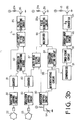
- Fig. 3a showing the control unit 56
- outputs of sensors 52 to 54 are applied to a microcomputer 58 through an input signal adjusting circuits 57.
- the microcomputer comprises an input-output (I/O) interface 59, ROM 60 in which various table maps are stored, RAM 61 for storing signals from the sensors, CPU 73, oscillator 62, timer 63 and counter 64.
- Output signals from the I/O interface 59 are applied to the solenoid-operated valves 43 and 51 and the electromagnetic clutch 1 through output signal adjusting circuits 65.
- Fig. 3b is a block diagram showing another example of the control unit 56.
- Output pulses from the primary pulley speed sensor 52 are shaped by a waveform shaping circuit 80 and counted by a counter 81.
- Output pulses from the secondary pulley speed sensor 53 are applied to a counter 83 through the waveform shaping circuit 80.
- Outputs from the counters 81 and 83 are applied to a transmission ratio computing circuit 82 to compute the transmission ratio.
- Output from counter 81 and output from computing circuit 82 are applied to a duty ratio setting circuit 84, output from which is applied-to a pulse generating circuit 85.
- the circuit 85 produces pulses having a duty ratio dependent on the output of the circuit 84.
- Output pulses from the circuit 85 operate a transistor 86 to excite a solenoid 43a of the solenoid operated valve 43 for the pressure regulator valve 67 at the duty ratio.
- Output from throttle position sensor 54 is applied to a duty ratio setting circuit 87 through a waveform shaping circuit 80, and an output from the counter 83 is also applied to the circuit 87 so as to set a duty ratio for the solenoid operated valve 51.
- the output from the waveform shaping circuit 80 is applied to a differentiating circuit 88, so that the opening speed of the throttle valve of the engine can be obtained by differentiating that output.
- An output from the differentiating circuit 88 is applied to a correction coefficient setting circuit 89 which produces a correction coefficient dependent on the throttle valve opening speed.
- Outputs from duty ratio setting circuit 87 and correction coefficient setting circuit 89 are applied to a multiplier 90 which produces a duty ratio signal corrected by the correction coefficient.
- a pulse generating.circuit 85a produces pulses having a duty ratio dependent on the duty ratio signal from the multiplier 90. The pulses operate a transistor 86 which excites a solenoid 51a of the solenoid operated valve 51 for the transmission ratio control valve 44.
- the output of the differentiating circuit 88 is applied to a comparator 91 at which the output is compared with a reference value.
- An output signal from the comparator 91 is applied to a current drop setting circuit 93 through a timer count circuit 92.
- Output from the current drop setting circuit 93 is applied to a transistor 86 through a D/A converter 94 to control the current passing through the coil 8 of the electromagnetic powder clutch 1.
- the solenoid operated valve 43 is intermittently opened at a duty ratio which is decided by the transmission ratio and the speed of the primary pulley 24 as described above.
- the operation of the solenoid operated valve 43 acts to regulate the pressure in the chamber 69 of the pressure regulator valve 67 to control the line pressure in passages 39 and 39a.
- the line pressure is raised as the transmission ratio or the engine speed increases, so that the movable conical disc 24a is pressed against the belt 26 at high pressure.
- the belt transmits the power to the secondary pulley 28 without slipping at high transmission ratio or high engine speed.
- the solenoid operated valve 51 is operated at a duty ratio dependent on transmission ratio which is corrected by the speed of the throttle valve when opened.
- the operation of the valve 51 controls the pressure in the chamber 47 of the transmission ratio control valve 44 to control the amount of pressurized oil supplied to the chamber 27b of the servo device 27.
- the pressure in the chamber 47 increases with the increase in the opening degree of the throttle valve, so that the amount of the discharge oil in the chamber 27 increases.
- the transmission ratio increases with the increase in the opening degree of the throttle valve.
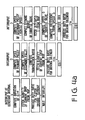
- a duty ratio D is fetched from a map of figure 4d depending on the vehicle speed (speed of the secondary pulley) and the opening degree 0 of the throttle valve.
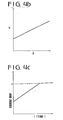
- a correction coefficient K is obtained from a graph of Fig. 4b in accordance with the throttle valve opening speed 8.
- the duty ratio D is multiplied by coefficient K to obtain a duty ratio signal for the transmission ratio which is applied to the solenoid operated valve 51.
- a duty ratio Di is fetched from a map of Fig. 4e depending on the speed of the primary pulley N and transmission ratio (i) which is obtained from the speeds of the primary and secondary pulleys.
- the signal dependent on the duty ratio Di is applied to the solenoid operated valve 43. Further, duration of the speed 6 higher than a reference level ⁇ is computed.
- the current drop quantity is obtained from a graph of Fig. 4c depending on the period. From these data, the transmission ratio is shifted down depending on the magnitude of opening speed ⁇ of the throttle valve. The quantity of downshift is increased with the increase of the speed of the throttle valve.
Priority Applications (1)
| Application Number | Priority Date | Filing Date | Title |
|---|---|---|---|
| AT85302736T ATE47817T1 (de) | 1984-04-19 | 1985-04-18 | System zum einstellen des uebersetzungsverhaeltnisses eines stufenlosen getriebes. |
Applications Claiming Priority (2)
| Application Number | Priority Date | Filing Date | Title |
|---|---|---|---|
| JP59079746A JPS60222649A (ja) | 1984-04-19 | 1984-04-19 | 電子式無段変速機の変速比制御装置 |
| JP79746/84 | 1984-04-19 |
Publications (2)
| Publication Number | Publication Date |
|---|---|
| EP0161824A1 true EP0161824A1 (de) | 1985-11-21 |
| EP0161824B1 EP0161824B1 (de) | 1989-11-08 |
Family
ID=13698788
Family Applications (1)
| Application Number | Title | Priority Date | Filing Date |
|---|---|---|---|
| EP85302736A Expired EP0161824B1 (de) | 1984-04-19 | 1985-04-18 | System zum Einstellen des Übersetzungsverhältnisses eines stufenlosen Getriebes |
Country Status (7)
| Country | Link |
|---|---|
| US (1) | US4680990A (de) |
| EP (1) | EP0161824B1 (de) |
| JP (1) | JPS60222649A (de) |
| AT (1) | ATE47817T1 (de) |
| AU (1) | AU556657B2 (de) |
| CA (1) | CA1233045A (de) |
| DE (2) | DE3574120D1 (de) |
Cited By (10)
| Publication number | Priority date | Publication date | Assignee | Title |
|---|---|---|---|---|
| EP0205257A1 (de) * | 1985-06-29 | 1986-12-17 | Fuji Jukogyo Kabushiki Kaisha | Leitungsdrucksteuervorrichtung für ein stufenlos regelbares Getriebe |
| EP0217606A1 (de) * | 1985-09-20 | 1987-04-08 | Fuji Jukogyo Kabushiki Kaisha | Steuervorrichtung für ein stufenlos regelbares Getriebe |
| EP0228804A1 (de) * | 1985-11-22 | 1987-07-15 | Fuji Jukogyo Kabushiki Kaisha | Hydraulische Steuereinrichtung für den Leitungsdruck eines stufenlos verstellbaren Getriebes |
| EP0231059A1 (de) * | 1986-01-07 | 1987-08-05 | Fuji Jukogyo Kabushiki Kaisha | Steuervorrichtung für ein stufenlos regelbares Getriebe |
| EP0240285A2 (de) * | 1986-03-31 | 1987-10-07 | Fuji Jukogyo Kabushiki Kaisha | Steuervorrichtung für ein stufenlos regelbares Getriebe |
| EP0240282A2 (de) * | 1986-03-31 | 1987-10-07 | Fuji Jukogyo Kabushiki Kaisha | Steuervorrichtung für den Öldruck eines stufenlos regelbaren Getriebes |
| EP0258004A1 (de) * | 1986-08-23 | 1988-03-02 | Fuji Jukogyo Kabushiki Kaisha | Steuervorrichtung für ein stufenlos regelbares Getriebe |
| EP0257958A1 (de) * | 1986-08-20 | 1988-03-02 | Fuji Jukogyo Kabushiki Kaisha | Steuereinrichtung für ein stufenlos regelbares Getriebe |
| EP0330422A2 (de) * | 1988-02-22 | 1989-08-30 | Fuji Jukogyo Kabushiki Kaisha | Steuerung für ein stufenlos verstellbares Getriebe |
| GB2303181A (en) * | 1995-07-08 | 1997-02-12 | Bosch Gmbh Robert | Adaptive automatic transmission control |
Families Citing this family (14)
| Publication number | Priority date | Publication date | Assignee | Title |
|---|---|---|---|---|
| JPS6231761A (ja) * | 1985-08-02 | 1987-02-10 | Toyota Central Res & Dev Lab Inc | 無段変速機の速度比制御装置 |
| JPH0624895B2 (ja) * | 1985-08-30 | 1994-04-06 | 富士重工業株式会社 | 無段変速機のライン圧制御装置 |
| JPH0657508B2 (ja) * | 1985-11-18 | 1994-08-03 | 富士重工業株式会社 | 無段変速機の制御装置 |
| JPS62227825A (ja) * | 1986-03-28 | 1987-10-06 | Fuji Heavy Ind Ltd | 無段変速機の制御装置 |
| JPS6331833A (ja) * | 1986-07-25 | 1988-02-10 | Nissan Motor Co Ltd | Vベルト式無段変速機のライン圧制御装置 |
| US4708040A (en) * | 1987-01-27 | 1987-11-24 | Kennametal Inc. | Lock rod and apparatus for holding a toolholder |
| JPS6444394A (en) * | 1987-08-11 | 1989-02-16 | Honda Motor Co Ltd | Controller for non-stage transmission |
| JPH07111221B2 (ja) * | 1987-10-20 | 1995-11-29 | 本田技研工業株式会社 | 車両用無段変速機の変速制御方法 |
| JPH01132431A (ja) * | 1987-11-16 | 1989-05-24 | Honda Motor Co Ltd | 車両用無段変速機の変速制御方法 |
| BE1004750A3 (nl) * | 1990-11-22 | 1993-01-19 | Volvo Car Sint Truiden Nv | Werkwijze en inrichting voor het regelen van een automatische transmissie-eenheid bij motorvoertuigen. |
| EP0588896B1 (de) * | 1991-06-21 | 1994-11-09 | Dr.Ing.h.c. F. Porsche Aktiengesellschaft | Verfahren zur steuerung eines automatisch betätigten getriebes eines kraftfahrzeugs |
| JP3640477B2 (ja) * | 1996-10-11 | 2005-04-20 | 本田技研工業株式会社 | 無段変速機における油圧制御装置 |
| DE10018245A1 (de) * | 1999-04-16 | 2000-10-26 | Luk Lamellen & Kupplungsbau | Kraftfahrzeug |
| JP3785901B2 (ja) * | 2000-05-19 | 2006-06-14 | トヨタ自動車株式会社 | 無段変速機の変速制御装置 |
Citations (8)
| Publication number | Priority date | Publication date | Assignee | Title |
|---|---|---|---|---|
| DE2301776A1 (de) * | 1973-01-15 | 1974-08-01 | Piv Antrieb Reimers Kg Werner | Steuereinrichtung fuer einen antrieb mit einem motor und einem stufenlos einstellbaren kegelscheiben-umschlingungsgetreibe |
| GB2075620A (en) * | 1980-04-30 | 1981-11-18 | Aisin Warner | Hydraulic regulator for a v-belt type continuously variable transmission for vehicles |
| DE3145630A1 (de) * | 1980-11-19 | 1982-10-21 | Fuji Jukogyo K.K., Tokyo | Anordnung zum steuern einer elektromagnetischen kupplung eines kraftfahrzeugs |
| DE3139838A1 (de) * | 1981-10-07 | 1983-04-21 | Bosch Gmbh Robert | Verfahren zum steuern von automatischen stufengetrieben in kraftfahrzeugen |
| EP0092227A1 (de) * | 1982-04-19 | 1983-10-26 | Nissan Motor Co., Ltd. | Verfahren zum Verstellen des Übersetzungsverhältnisses eines stufenlosen Getriebes unter Anpassung der Beschleunigung |
| EP0093312A1 (de) * | 1982-04-19 | 1983-11-09 | Nissan Motor Co., Ltd. | Verfahren und Vorrichtung zur Steuerung des Untersetzungsverhältnisses eines stufenlos variablen Getriebes mit Ausgleich der Geschwindigkeit der Gaspedalbetätigung |
| EP0101151A1 (de) * | 1982-08-06 | 1984-02-22 | General Motors Corporation | Steuersystem für Getriebe mit stufenlos veränderbarem Geschwindigkeitsverhältnis |
| EP0120686A1 (de) * | 1983-03-23 | 1984-10-03 | Fuji Jukogyo Kabushiki Kaisha | Stufenlos einstellbares Regelriemengetriebe |
Family Cites Families (12)
| Publication number | Priority date | Publication date | Assignee | Title |
|---|---|---|---|---|
| FR2464853B1 (fr) * | 1979-09-12 | 1987-07-31 | Bosch Gmbh Robert | Installation de commande pour variateur de vitesse continu de vehicule automobile |
| US4387608A (en) * | 1979-09-12 | 1983-06-14 | Robert Bosch Gmbh | Electronic control for a stepless vehicle transmission using a control member response to dynamic pressure |
| JPS5683646A (en) * | 1979-12-11 | 1981-07-08 | Nissan Motor Co Ltd | Controlling device for kickdown of automatic speed change gear |
| JPS56134658A (en) * | 1980-03-24 | 1981-10-21 | Aisin Warner Ltd | Controller for torque ratio of v-bent type stepless transmission for vehicle |
| US4457411A (en) * | 1980-06-02 | 1984-07-03 | Mitsubishi Jidosha Kogyo Kabushiki Kaisha | Torque transmission device |
| US4484672A (en) * | 1980-07-28 | 1984-11-27 | Fuji Jukogyo Kabushiki Kaisha | System for controlling an electro-magnetic clutch for automobiles |
| DE3036327A1 (de) * | 1980-09-26 | 1982-05-27 | Volkswagenwerk Ag, 3180 Wolfsburg | Antrieb fuer ein fahrzeug, insbesondere fuer strassenfahrzeug |
| US4458318A (en) * | 1981-04-24 | 1984-07-03 | Borg-Warner Corporation | Control arrangement for a variable pulley transmission |
| JPS58146750A (ja) * | 1982-02-22 | 1983-09-01 | Nissan Motor Co Ltd | 自動変速機の変速制御装置 |
| JPS5926657A (ja) * | 1982-08-04 | 1984-02-10 | Toyota Motor Corp | 無段変速式動力伝達装置を備えた車両の制御装置 |
| US4534243A (en) * | 1983-04-26 | 1985-08-13 | Aisin Warner Kabushiki Kaisha | Hydraulic control system for a V-belt transmission |
| US4547178A (en) * | 1983-12-01 | 1985-10-15 | Fuji Medical Instruments Mfg. Co., Ltd. | Control system for an automatic transmission for a vehicle |
-
1984
- 1984-04-19 JP JP59079746A patent/JPS60222649A/ja active Granted
-
1985
- 1985-04-12 US US06/722,961 patent/US4680990A/en not_active Expired - Fee Related
- 1985-04-17 CA CA000479354A patent/CA1233045A/en not_active Expired
- 1985-04-18 AT AT85302736T patent/ATE47817T1/de not_active IP Right Cessation
- 1985-04-18 EP EP85302736A patent/EP0161824B1/de not_active Expired
- 1985-04-18 DE DE8585302736T patent/DE3574120D1/de not_active Expired
- 1985-04-18 AU AU41404/85A patent/AU556657B2/en not_active Ceased
- 1985-04-18 DE DE198585302736T patent/DE161824T1/de active Pending
Patent Citations (8)
| Publication number | Priority date | Publication date | Assignee | Title |
|---|---|---|---|---|
| DE2301776A1 (de) * | 1973-01-15 | 1974-08-01 | Piv Antrieb Reimers Kg Werner | Steuereinrichtung fuer einen antrieb mit einem motor und einem stufenlos einstellbaren kegelscheiben-umschlingungsgetreibe |
| GB2075620A (en) * | 1980-04-30 | 1981-11-18 | Aisin Warner | Hydraulic regulator for a v-belt type continuously variable transmission for vehicles |
| DE3145630A1 (de) * | 1980-11-19 | 1982-10-21 | Fuji Jukogyo K.K., Tokyo | Anordnung zum steuern einer elektromagnetischen kupplung eines kraftfahrzeugs |
| DE3139838A1 (de) * | 1981-10-07 | 1983-04-21 | Bosch Gmbh Robert | Verfahren zum steuern von automatischen stufengetrieben in kraftfahrzeugen |
| EP0092227A1 (de) * | 1982-04-19 | 1983-10-26 | Nissan Motor Co., Ltd. | Verfahren zum Verstellen des Übersetzungsverhältnisses eines stufenlosen Getriebes unter Anpassung der Beschleunigung |
| EP0093312A1 (de) * | 1982-04-19 | 1983-11-09 | Nissan Motor Co., Ltd. | Verfahren und Vorrichtung zur Steuerung des Untersetzungsverhältnisses eines stufenlos variablen Getriebes mit Ausgleich der Geschwindigkeit der Gaspedalbetätigung |
| EP0101151A1 (de) * | 1982-08-06 | 1984-02-22 | General Motors Corporation | Steuersystem für Getriebe mit stufenlos veränderbarem Geschwindigkeitsverhältnis |
| EP0120686A1 (de) * | 1983-03-23 | 1984-10-03 | Fuji Jukogyo Kabushiki Kaisha | Stufenlos einstellbares Regelriemengetriebe |
Cited By (15)
| Publication number | Priority date | Publication date | Assignee | Title |
|---|---|---|---|---|
| EP0205257A1 (de) * | 1985-06-29 | 1986-12-17 | Fuji Jukogyo Kabushiki Kaisha | Leitungsdrucksteuervorrichtung für ein stufenlos regelbares Getriebe |
| EP0217606A1 (de) * | 1985-09-20 | 1987-04-08 | Fuji Jukogyo Kabushiki Kaisha | Steuervorrichtung für ein stufenlos regelbares Getriebe |
| EP0228804A1 (de) * | 1985-11-22 | 1987-07-15 | Fuji Jukogyo Kabushiki Kaisha | Hydraulische Steuereinrichtung für den Leitungsdruck eines stufenlos verstellbaren Getriebes |
| EP0231059A1 (de) * | 1986-01-07 | 1987-08-05 | Fuji Jukogyo Kabushiki Kaisha | Steuervorrichtung für ein stufenlos regelbares Getriebe |
| EP0240282A3 (en) * | 1986-03-31 | 1988-04-27 | Fuji Jukogyo Kabushiki Kaisha | System for controlling the pressure of oil in a system for a continuously variable transmission |
| EP0240282A2 (de) * | 1986-03-31 | 1987-10-07 | Fuji Jukogyo Kabushiki Kaisha | Steuervorrichtung für den Öldruck eines stufenlos regelbaren Getriebes |
| EP0240285A3 (en) * | 1986-03-31 | 1988-04-27 | Fuji Jukogyo Kabushiki Kaisha | Transmission ratio control system for a continuously variable transmission |
| EP0240285A2 (de) * | 1986-03-31 | 1987-10-07 | Fuji Jukogyo Kabushiki Kaisha | Steuervorrichtung für ein stufenlos regelbares Getriebe |
| EP0257958A1 (de) * | 1986-08-20 | 1988-03-02 | Fuji Jukogyo Kabushiki Kaisha | Steuereinrichtung für ein stufenlos regelbares Getriebe |
| EP0258004A1 (de) * | 1986-08-23 | 1988-03-02 | Fuji Jukogyo Kabushiki Kaisha | Steuervorrichtung für ein stufenlos regelbares Getriebe |
| EP0330422A2 (de) * | 1988-02-22 | 1989-08-30 | Fuji Jukogyo Kabushiki Kaisha | Steuerung für ein stufenlos verstellbares Getriebe |
| EP0330422A3 (en) * | 1988-02-22 | 1990-10-03 | Fuji Jukogyo Kabushiki Kaisha | Control system for a continuously variable transmission |
| GB2303181A (en) * | 1995-07-08 | 1997-02-12 | Bosch Gmbh Robert | Adaptive automatic transmission control |
| GB2303181B (en) * | 1995-07-08 | 1997-09-10 | Bosch Gmbh Robert | Adaptive transmission control |
| US5954777A (en) * | 1995-07-08 | 1999-09-21 | Robert Bosch Gmbh | Adaptive transmission control |
Also Published As
| Publication number | Publication date |
|---|---|
| DE3574120D1 (en) | 1989-12-14 |
| JPH0586493B2 (de) | 1993-12-13 |
| ATE47817T1 (de) | 1989-11-15 |
| CA1233045A (en) | 1988-02-23 |
| AU4140485A (en) | 1985-10-24 |
| EP0161824B1 (de) | 1989-11-08 |
| AU556657B2 (en) | 1986-11-13 |
| JPS60222649A (ja) | 1985-11-07 |
| US4680990A (en) | 1987-07-21 |
| DE161824T1 (de) | 1986-04-10 |
Similar Documents
| Publication | Publication Date | Title |
|---|---|---|
| EP0161824B1 (de) | System zum Einstellen des Übersetzungsverhältnisses eines stufenlosen Getriebes | |
| US4663991A (en) | System for controlling the transmission ratio of an infinitely variable transmission | |
| US4672864A (en) | Control system for an infinitely variable transmission | |
| US4680987A (en) | Control system for an infinitely variable transmission | |
| US4651595A (en) | Kickdown system for an infinitely variable transmission | |
| EP0207231B1 (de) | Steuersystem für ein stufenlos veränderbares Getriebe | |
| EP0257960B1 (de) | Steuereinrichtung für ein stufenlos regelbares Getriebe | |
| EP0134725B1 (de) | Stufenloses Getriebe | |
| EP0239365B1 (de) | Steuerung für das Übersetzungsverhältnis eines stufenlosen Antriebes | |
| EP0207227B1 (de) | Steuersystem für stufenlose Getriebe | |
| EP0221668B1 (de) | Steuersystem für ein stufenloses Getriebe | |
| EP0172740B1 (de) | Steuerung für ein stufenloses Getriebe | |
| EP0207603B1 (de) | Steuersystem für ein stufenloses Getriebe | |
| EP0147153A2 (de) | Anzeigevorrichtung des Übersetzungsverhältnisses für ein stufenlos verstellbares Riemengetriebe mit Schmiereinrichtung | |
| EP0205257B1 (de) | Leitungsdrucksteuervorrichtung für ein stufenlos regelbares Getriebe | |
| CA1204304A (en) | Controlling system for an infinitely variable belt- drive transmission | |
| EP0143667B1 (de) | Steuereinrichtung für ein stufenlos regelbares Getriebe | |
| EP0207228B1 (de) | Steuersystem für ein stufenloses Getriebe | |
| US4657522A (en) | Control system for an infinitely variable transmission | |
| US4675818A (en) | System for controlling an electromagnetic clutch for an automotive engine | |
| EP0225153A2 (de) | Steuerung für ein stufenlos veränderbares Getriebe | |
| US4656892A (en) | Control system for an infinitely variable transmission | |
| EP0172748A1 (de) | Steuerung für ein stufenloses Getriebe |
Legal Events
| Date | Code | Title | Description |
|---|---|---|---|
| PUAI | Public reference made under article 153(3) epc to a published international application that has entered the european phase |
Free format text: ORIGINAL CODE: 0009012 |
|
| 17P | Request for examination filed |
Effective date: 19850503 |
|
| AK | Designated contracting states |
Designated state(s): AT CH DE FR GB IT LI NL SE |
|
| ITCL | It: translation for ep claims filed |
Representative=s name: STUDIO BIANCHETTI |
|
| EL | Fr: translation of claims filed | ||
| TCNL | Nl: translation of patent claims filed | ||
| TCAT | At: translation of patent claims filed | ||
| DET | De: translation of patent claims | ||
| 17Q | First examination report despatched |
Effective date: 19870505 |
|
| GRAA | (expected) grant |
Free format text: ORIGINAL CODE: 0009210 |
|
| AK | Designated contracting states |
Kind code of ref document: B1 Designated state(s): AT CH DE FR GB IT LI NL SE |
|
| REF | Corresponds to: |
Ref document number: 47817 Country of ref document: AT Date of ref document: 19891115 Kind code of ref document: T |
|
| ITF | It: translation for a ep patent filed |
Owner name: STUDIO CONS. BREVETTUALE S.R.L. |
|
| ET | Fr: translation filed | ||
| REF | Corresponds to: |
Ref document number: 3574120 Country of ref document: DE Date of ref document: 19891214 |
|
| PLBE | No opposition filed within time limit |
Free format text: ORIGINAL CODE: 0009261 |
|
| STAA | Information on the status of an ep patent application or granted ep patent |
Free format text: STATUS: NO OPPOSITION FILED WITHIN TIME LIMIT |
|
| 26N | No opposition filed | ||
| ITTA | It: last paid annual fee | ||
| PGFP | Annual fee paid to national office [announced via postgrant information from national office to epo] |
Ref country code: FR Payment date: 19920326 Year of fee payment: 8 |
|
| PGFP | Annual fee paid to national office [announced via postgrant information from national office to epo] |
Ref country code: CH Payment date: 19920327 Year of fee payment: 8 |
|
| PGFP | Annual fee paid to national office [announced via postgrant information from national office to epo] |
Ref country code: GB Payment date: 19920401 Year of fee payment: 8 |
|
| PGFP | Annual fee paid to national office [announced via postgrant information from national office to epo] |
Ref country code: SE Payment date: 19920416 Year of fee payment: 8 |
|
| PGFP | Annual fee paid to national office [announced via postgrant information from national office to epo] |
Ref country code: NL Payment date: 19920430 Year of fee payment: 8 Ref country code: DE Payment date: 19920430 Year of fee payment: 8 Ref country code: AT Payment date: 19920430 Year of fee payment: 8 |
|
| PG25 | Lapsed in a contracting state [announced via postgrant information from national office to epo] |
Ref country code: GB Effective date: 19930418 Ref country code: AT Effective date: 19930418 |
|
| PG25 | Lapsed in a contracting state [announced via postgrant information from national office to epo] |
Ref country code: SE Effective date: 19930419 |
|
| PG25 | Lapsed in a contracting state [announced via postgrant information from national office to epo] |
Ref country code: LI Effective date: 19930430 Ref country code: CH Effective date: 19930430 |
|
| PG25 | Lapsed in a contracting state [announced via postgrant information from national office to epo] |
Ref country code: NL Effective date: 19931101 |
|
| GBPC | Gb: european patent ceased through non-payment of renewal fee |
Effective date: 19930418 |
|
| NLV4 | Nl: lapsed or anulled due to non-payment of the annual fee | ||
| PG25 | Lapsed in a contracting state [announced via postgrant information from national office to epo] |
Ref country code: FR Effective date: 19931229 |
|
| REG | Reference to a national code |
Ref country code: CH Ref legal event code: PL |
|
| PG25 | Lapsed in a contracting state [announced via postgrant information from national office to epo] |
Ref country code: DE Effective date: 19940101 |
|
| REG | Reference to a national code |
Ref country code: FR Ref legal event code: ST |
|
| EUG | Se: european patent has lapsed |
Ref document number: 85302736.5 Effective date: 19931110 |