EP0161633B1 - Image reproduction by in plane electro-coagulation of a colloid - Google Patents
Image reproduction by in plane electro-coagulation of a colloid Download PDFInfo
- Publication number
- EP0161633B1 EP0161633B1 EP85105683A EP85105683A EP0161633B1 EP 0161633 B1 EP0161633 B1 EP 0161633B1 EP 85105683 A EP85105683 A EP 85105683A EP 85105683 A EP85105683 A EP 85105683A EP 0161633 B1 EP0161633 B1 EP 0161633B1
- Authority
- EP
- European Patent Office
- Prior art keywords
- negative
- colloid
- matrix
- positive electrode
- positive
- Prior art date
- Legal status (The legal status is an assumption and is not a legal conclusion. Google has not performed a legal analysis and makes no representation as to the accuracy of the status listed.)
- Expired
Links
- 239000000084 colloidal system Substances 0.000 title claims abstract description 52
- 238000009297 electrocoagulation Methods 0.000 title claims abstract description 11
- 239000011159 matrix material Substances 0.000 claims abstract description 61
- 238000001246 colloidal dispersion Methods 0.000 claims abstract description 16
- 238000000034 method Methods 0.000 claims abstract description 16
- 239000007788 liquid Substances 0.000 claims abstract description 13
- 230000015271 coagulation Effects 0.000 claims abstract description 10
- 238000005345 coagulation Methods 0.000 claims abstract description 10
- 239000003792 electrolyte Substances 0.000 claims abstract description 9
- 238000010408 sweeping Methods 0.000 claims description 14
- 239000011810 insulating material Substances 0.000 claims description 9
- XLYOFNOQVPJJNP-UHFFFAOYSA-N water Substances O XLYOFNOQVPJJNP-UHFFFAOYSA-N 0.000 claims description 7
- WCUXLLCKKVVCTQ-UHFFFAOYSA-M Potassium chloride Chemical compound [Cl-].[K+] WCUXLLCKKVVCTQ-UHFFFAOYSA-M 0.000 claims description 6
- NLXLAEXVIDQMFP-UHFFFAOYSA-N Ammonia chloride Chemical compound [NH4+].[Cl-] NLXLAEXVIDQMFP-UHFFFAOYSA-N 0.000 claims description 4
- FAPWRFPIFSIZLT-UHFFFAOYSA-M Sodium chloride Chemical compound [Na+].[Cl-] FAPWRFPIFSIZLT-UHFFFAOYSA-M 0.000 claims description 4
- 230000005684 electric field Effects 0.000 claims description 4
- KWGKDLIKAYFUFQ-UHFFFAOYSA-M lithium chloride Chemical compound [Li+].[Cl-] KWGKDLIKAYFUFQ-UHFFFAOYSA-M 0.000 claims description 4
- 229920001577 copolymer Polymers 0.000 claims description 3
- 239000001103 potassium chloride Substances 0.000 claims description 3
- 235000011164 potassium chloride Nutrition 0.000 claims description 3
- UXVMQQNJUSDDNG-UHFFFAOYSA-L Calcium chloride Chemical compound [Cl-].[Cl-].[Ca+2] UXVMQQNJUSDDNG-UHFFFAOYSA-L 0.000 claims description 2
- 108010082495 Dietary Plant Proteins Proteins 0.000 claims description 2
- 229910021586 Nickel(II) chloride Inorganic materials 0.000 claims description 2
- 239000004372 Polyvinyl alcohol Substances 0.000 claims description 2
- 229920002125 Sokalan® Polymers 0.000 claims description 2
- 235000019270 ammonium chloride Nutrition 0.000 claims description 2
- 239000001110 calcium chloride Substances 0.000 claims description 2
- 229910001628 calcium chloride Inorganic materials 0.000 claims description 2
- 229940099596 manganese sulfate Drugs 0.000 claims description 2
- 239000011702 manganese sulphate Substances 0.000 claims description 2
- 235000007079 manganese sulphate Nutrition 0.000 claims description 2
- SQQMAOCOWKFBNP-UHFFFAOYSA-L manganese(II) sulfate Chemical compound [Mn+2].[O-]S([O-])(=O)=O SQQMAOCOWKFBNP-UHFFFAOYSA-L 0.000 claims description 2
- QMMRZOWCJAIUJA-UHFFFAOYSA-L nickel dichloride Chemical compound Cl[Ni]Cl QMMRZOWCJAIUJA-UHFFFAOYSA-L 0.000 claims description 2
- 229920002401 polyacrylamide Polymers 0.000 claims description 2
- 239000004584 polyacrylic acid Substances 0.000 claims description 2
- 229920002451 polyvinyl alcohol Polymers 0.000 claims description 2
- 239000011780 sodium chloride Substances 0.000 claims description 2
- 238000004040 coloring Methods 0.000 claims 1
- ORTQZVOHEJQUHG-UHFFFAOYSA-L copper(II) chloride Chemical compound Cl[Cu]Cl ORTQZVOHEJQUHG-UHFFFAOYSA-L 0.000 claims 1
- 230000008878 coupling Effects 0.000 claims 1
- 238000010168 coupling process Methods 0.000 claims 1
- 238000005859 coupling reaction Methods 0.000 claims 1
- 102000009027 Albumins Human genes 0.000 description 3
- 108010088751 Albumins Proteins 0.000 description 3
- 108010010803 Gelatin Proteins 0.000 description 3
- 229920000159 gelatin Polymers 0.000 description 3
- 239000008273 gelatin Substances 0.000 description 3
- 235000019322 gelatine Nutrition 0.000 description 3
- 235000011852 gelatine desserts Nutrition 0.000 description 3
- 229910052751 metal Inorganic materials 0.000 description 3
- 239000002184 metal Substances 0.000 description 3
- PXHVJJICTQNCMI-UHFFFAOYSA-N Nickel Chemical compound [Ni] PXHVJJICTQNCMI-UHFFFAOYSA-N 0.000 description 2
- 238000009825 accumulation Methods 0.000 description 2
- 239000007789 gas Substances 0.000 description 2
- 239000000203 mixture Substances 0.000 description 2
- 230000010287 polarization Effects 0.000 description 2
- LIVNPJMFVYWSIS-UHFFFAOYSA-N silicon monoxide Chemical compound [Si-]#[O+] LIVNPJMFVYWSIS-UHFFFAOYSA-N 0.000 description 2
- 229910001220 stainless steel Inorganic materials 0.000 description 2
- 239000010935 stainless steel Substances 0.000 description 2
- 229920001817 Agar Polymers 0.000 description 1
- 108010076119 Caseins Proteins 0.000 description 1
- VYZAMTAEIAYCRO-UHFFFAOYSA-N Chromium Chemical compound [Cr] VYZAMTAEIAYCRO-UHFFFAOYSA-N 0.000 description 1
- RYGMFSIKBFXOCR-UHFFFAOYSA-N Copper Chemical compound [Cu] RYGMFSIKBFXOCR-UHFFFAOYSA-N 0.000 description 1
- UFHFLCQGNIYNRP-UHFFFAOYSA-N Hydrogen Chemical compound [H][H] UFHFLCQGNIYNRP-UHFFFAOYSA-N 0.000 description 1
- ATJFFYVFTNAWJD-UHFFFAOYSA-N Tin Chemical compound [Sn] ATJFFYVFTNAWJD-UHFFFAOYSA-N 0.000 description 1
- 230000002411 adverse Effects 0.000 description 1
- 239000008272 agar Substances 0.000 description 1
- 229910052782 aluminium Inorganic materials 0.000 description 1
- XAGFODPZIPBFFR-UHFFFAOYSA-N aluminium Chemical compound [Al] XAGFODPZIPBFFR-UHFFFAOYSA-N 0.000 description 1
- 235000021120 animal protein Nutrition 0.000 description 1
- 239000003990 capacitor Substances 0.000 description 1
- 239000005018 casein Substances 0.000 description 1
- BECPQYXYKAMYBN-UHFFFAOYSA-N casein, tech. Chemical compound NCCCCC(C(O)=O)N=C(O)C(CC(O)=O)N=C(O)C(CCC(O)=N)N=C(O)C(CC(C)C)N=C(O)C(CCC(O)=O)N=C(O)C(CC(O)=O)N=C(O)C(CCC(O)=O)N=C(O)C(C(C)O)N=C(O)C(CCC(O)=N)N=C(O)C(CCC(O)=N)N=C(O)C(CCC(O)=N)N=C(O)C(CCC(O)=O)N=C(O)C(CCC(O)=O)N=C(O)C(COP(O)(O)=O)N=C(O)C(CCC(O)=N)N=C(O)C(N)CC1=CC=CC=C1 BECPQYXYKAMYBN-UHFFFAOYSA-N 0.000 description 1
- 235000021240 caseins Nutrition 0.000 description 1
- 150000001805 chlorine compounds Chemical class 0.000 description 1
- 229910052804 chromium Inorganic materials 0.000 description 1
- 239000011651 chromium Substances 0.000 description 1
- 229910052802 copper Inorganic materials 0.000 description 1
- 239000010949 copper Substances 0.000 description 1
- 239000001257 hydrogen Substances 0.000 description 1
- 229910052739 hydrogen Inorganic materials 0.000 description 1
- 150000002500 ions Chemical class 0.000 description 1
- 150000002739 metals Chemical class 0.000 description 1
- 229910052759 nickel Inorganic materials 0.000 description 1
- 239000000049 pigment Substances 0.000 description 1
- 238000004544 sputter deposition Methods 0.000 description 1
- 150000003467 sulfuric acid derivatives Chemical class 0.000 description 1
- 239000011135 tin Substances 0.000 description 1
- 229910052718 tin Inorganic materials 0.000 description 1
- 238000005406 washing Methods 0.000 description 1
Images
Classifications
-
- B—PERFORMING OPERATIONS; TRANSPORTING
- B41—PRINTING; LINING MACHINES; TYPEWRITERS; STAMPS
- B41M—PRINTING, DUPLICATING, MARKING, OR COPYING PROCESSES; COLOUR PRINTING
- B41M5/00—Duplicating or marking methods; Sheet materials for use therein
-
- B—PERFORMING OPERATIONS; TRANSPORTING
- B41—PRINTING; LINING MACHINES; TYPEWRITERS; STAMPS
- B41C—PROCESSES FOR THE MANUFACTURE OR REPRODUCTION OF PRINTING SURFACES
- B41C1/00—Forme preparation
- B41C1/10—Forme preparation for lithographic printing; Master sheets for transferring a lithographic image to the forme
- B41C1/105—Forme preparation for lithographic printing; Master sheets for transferring a lithographic image to the forme by electrocoagulation, by electro-adhesion or by electro-releasing of material, e.g. a liquid from a gel
Definitions
- the present invention relates to improvements in high speed image reproduction. More particularly, the invention is concerned with an improved method and system for reproducing an image by the electro-coagulation of an electrolytically coagulable colloid.
- Applicant has already described in his U.S. Patent No. 3,892,645 of July 1, 1975 an electric printing method and system in which a thin layer of a liquid composition containing a colloid such as gelatin or albumin, water and an electrolyte is interposed between at least one pair of opposite negative and positive electrodes spaced from one another to define a gap which is filled by the liquid composition.
- a liquid composition containing a colloid such as gelatin or albumin, water and an electrolyte
- the gap between the negative and positive electrodes be uniform throughout the active surfaces of the electrodes since otherwise there will be a variation in the thickness of the layer and thus a corresponding variation of the electrical resistance thereof at different locations between the electrodes, which will result in a non-uniform image reproduction as the thickness of the coagulated colloid is proportional to the amount of current passed through the layer. Since this gap is of the order to 50 11, its uniformity is of course very difficult to control. Moreover, where the negative electrodes are energized more than once in the reproduction of an image, these become polarized resulting in a gas generation and accumulation at the negative electrodes, which adversely affect the image reproduction.
- the invention also provides, in a further aspect thereof, a system for reproducing an image by electro-coagulation of an electrolytically coagulable colloid, which comprises:
- the negative and positive electrodes of the matrix comprise respectively first and second sets of mutually electrically-insulated band-like electrode members disposed in parallel side-by-side relation, the negative electrode members of the first set extending transversely of the positive electrode members of the second set and being formed with a plurality of protruding conductive elements which are spaced along the length thereof and each have a planar active end surface.
- the protruding elements of each negative electrode member extend through corresponding bores formed in the positive electrode members to terminate flush therewith such that the planar active end surface of each protruding element and a planar active surface portion of each positive electrode member adjacent each bore extend in a substantially common plane whereby to define the aforesaid matrix elements.
- the electrical energizing of the negative and positive electrodes of selected matrix elements may be effected by sequentially energizing the electrode members of one set and concurrently energizing selected ones of the electrode members of the other set.
- the positive electrode members are sequentially energized while selected ones of the negative electrode members are concurrently energized.
- the concurrent selective energizing of the electrode members of the other set is advantageously effected by sweeping such electrode members and transmitting electrical pulses to selected ones thereof during sweeping.
- These electrical pulses can be varied either in voltage or time from one electrode member to another so as to correspondingly vary the amount of coagulated colloid adhered onto the positive electrode active surfaces of the selected matrix elements. This enables one to form dots of varying intensities and thus to reproduce the half-tones of an image.
- the colloid generally used is a linear colloid of high molecular weight, that is, one having a molecular weight comprised between about 10,000 and about 1,000,000, preferably between 100,000 and 500,000.
- suitable colloids include animal proteins such as albumin, gelatin and casein, vegetable proteins such as agar and synthetic copolymers such as polyacrylic acid, polyacrylamide, polyvinyl alcohol and derivatives thereof. Water is preferably used as the medium for dispersing the colloid to provide the desired colloidal dispersion.
- the colloidal dispersion also contains a soluble electrolyte which enables the water to have a greater conductivity; the water is believed to migrate under direct current towards the negative electrode and thereby cause the colloidal dispersion to dry out, resulting in coagulation of the colloid and adherence thereof onto the positive electrode.
- suitable electrolytes include chlorides and sulfates, such as potassium chloride, sodium chloride, calcium chloride, nickel chloride, lithium chloride, ammonium chloride, and manganese sulfate. Since the speed of electro-coagulation is affected by temperature, the layer of colloidal dispersion must be maintained at a substantially constant temperature, for instance by using a thermostatic water jacket, in order to ensure a uniform image reproduction.
- any remaining non-coagulated colloid is removed by any suitable means, such as by washing off, airjet or wiping to fully uncover the coagulated colloid.
- the coagulated colloid can be colored with a hydrotypic pigment which is absorbed thereby and the colored coagulated colloid may then be transferred onto an end-use support, such as paper.
- the coagulated colloid can also be set or hardened chemically or by irradiation so as to be used for offset lithographic printing.
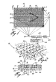
- the image reproduction system illustrated in Fig. 1 includes a dot matrix printer which is generally designated by reference numeral 10 and comprises two superimposed sets of electrically-insulated negative and positive band-like electrode members 12 and 14 disposed in parallel side-by-side relation, the negative electrode members 12 extending transversely of the positive electrode members 14 to define at their intersections a plurality of dot-forming matrix elements 16.
- Each negative electrode member 12 is electrically con- nectedto a sweeping device 18which is connected to the negative terminal of a direct current power supply 20 via a modulator 22 coupled to an electronic counter 24 operative to transmit electrical pulses to selected ones of the electrode members 12 during the sweeping thereof by the device 18.
- the modulator serves to vary the electrical pulses either in voltage or time.
- the electrodes of selected ones of the matrix elements 16 are electrically energized by sequentially energizing the positive electrode members 14 with the sweeping device 18' and concurrently sweeping the negative electrode members 12 with the device 18 while transmitting with the counter 24 electrical pulses to selected electrode members 12, which are modulated either in voltage or time by the modulator 22.
- the negative and positive electrode members are electrically insulated from one another by means of a layer of insulating material 26 having a thickness of about 10 11 .
- the negative electrode members 12 are also electrically insulated from one another by a layer of insulating material 28 having a thickness of about 25 11.
- the positive electrode members 14 are similarly insulated by means of a layer of insulating material 30 having a thickness of about 10 to 25 ⁇ , preferably 10 ⁇ .
- Each negative electrode member 12 is formed with a plurality of protruding conductive elements 32 of circular cross-section which are spaced along the length thereof and each have a planar active end surface 34.
- each protruding element 32 of each negative electrode 12 extend through corresponding bores 36 formed in the positive electrode members 14 to terminate flush therewith such that the planar active end surface 34 of each element 32 and a planar active surface portion 38 of a positive electrode member 14 adjacent a bore 36 extend in a common plane.
- Each protruding element 32 is of course electrically insulated from its adjacent positive electrode member 14 by means of a layer of insulating material 40 such as silicon monoxide, having a thickness of about 5 to 10 ⁇ , preferably 10 u.
- each protruding element 32 and the planar surface portion 38 of each positive electrode member 14 adjacent each element 32 constitute- the electrode active surfaces of each dot-forming matrix element 16.
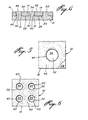
- Each matrix element preferably has a square surface area of about 125 p x 125 ⁇ , the protruding element 32 of each matrix element 16 being disposed centrally thereof and having a diameter of about 25 to 50 ⁇ ; the elements 32 are therefore invisible to the naked eye.
- the dot matrix printer 10 comprises about 40,000 of such matrix elements 16 per square inch.
- the negative electrode members 12 can be made of any metal, copper or stainless steel being preferred.
- the positive electrode members 14 must be made of a metal that will resist electrolytic attack and enhance electro-coagulation, such as stainless steel, aluminum, nickel, chromium or tin, these metals being electronegative with respect to hydrogen.
- the surfaces 38 of the positive electrode members 14 are advantageously unpolished to enhance the adherence of the coagulated colloid thereon.
- the electrode members 14 can be produced by ion sputtering and can thus be as thin as 10 p.
- a layer of a liquid colloidal dispersion containing a colloid such as gelatin or albumin, water and an electrolyte such as potassium chloride, and having a substantially uniform temperature throughout the layer is applied over the surface of the dot matrix printer 10.
- the sweeping devices 18 and 18' and the counter 24 are then activated so as to electrically energize the electrodes of selected ones of the matrix elements 16 and thereby cause selective coagulation and adherence of the colloid onto the positive electrode active surfaces 38 of the selected matrix elements, the coagulated colloid 42 forming a series of corresponding dots representative of the desired image.
- the layer of insulating material 30 between the positive electrode members 14 should be as thin as possible so as to provide a continuous " image and not one which is streaked.
- the layer of insulating material 40 surrounding each protruding element 32 should also be as thin as possible since the thinner the layer 40 the faster is the speed of electro-coagulation.
- matrix elements 16 each formed with a single centrally disposed protruding element 32 as shown in Fig. 5, it is of course also possible to provide matrix elements 16' each formed with a plurality of spaced-apart elements 32 as represented in the embodiment illustrated in Fig. 6. Such an arrangement enables one to produce an image having a more uniform tone repartition.
- the power required to produce coagulation over a square surface area of about 125 p x 125 11 is the charge of an electrolytic capacitor of 2 micro farads at 50 volts.
- a power generator of 25 watts (50 V, 500 mA) one can produce about 100,000 dots per second.
- the dot matrix printer 10 has been illustrated as having a planar display surface, it is apparent that the whole surfaces of the positive electrode members 14 which constitute the display surface of the printer 10 need not be planar, provided however that the electrode active surfaces of each matrix element be planar and extend in a substantially common plane.
- a cylindrical dot matrix printer could be designed in which each matrix element would have the required characteristic just mentioned.
Landscapes
- Chemical & Material Sciences (AREA)
- Dispersion Chemistry (AREA)
- Engineering & Computer Science (AREA)
- Manufacturing & Machinery (AREA)
- Electrochromic Elements, Electrophoresis, Or Variable Reflection Or Absorption Elements (AREA)
- Printers Or Recording Devices Using Electromagnetic And Radiation Means (AREA)
- Duplication Or Marking (AREA)
Priority Applications (1)
| Application Number | Priority Date | Filing Date | Title |
|---|---|---|---|
| AT85105683T ATE46659T1 (de) | 1984-05-16 | 1985-05-09 | Bildreproduktion durch flaechenelektrokoagulation von kolloiden. |
Applications Claiming Priority (2)
| Application Number | Priority Date | Filing Date | Title |
|---|---|---|---|
| CA454450 | 1984-05-16 | ||
| CA000454450A CA1205778A (en) | 1984-05-16 | 1984-05-16 | Image reproduction by in plane electro-coagulation of a colloid |
Publications (3)
| Publication Number | Publication Date |
|---|---|
| EP0161633A2 EP0161633A2 (en) | 1985-11-21 |
| EP0161633A3 EP0161633A3 (en) | 1987-08-05 |
| EP0161633B1 true EP0161633B1 (en) | 1989-09-27 |
Family
ID=4127877
Family Applications (1)
| Application Number | Title | Priority Date | Filing Date |
|---|---|---|---|
| EP85105683A Expired EP0161633B1 (en) | 1984-05-16 | 1985-05-09 | Image reproduction by in plane electro-coagulation of a colloid |
Country Status (8)
| Country | Link |
|---|---|
| EP (1) | EP0161633B1 (enExample) |
| JP (1) | JPS60259489A (enExample) |
| KR (1) | KR850008649A (enExample) |
| AT (1) | ATE46659T1 (enExample) |
| AU (1) | AU572293B2 (enExample) |
| CA (1) | CA1205778A (enExample) |
| DE (1) | DE3573234D1 (enExample) |
| ZA (1) | ZA853470B (enExample) |
Families Citing this family (6)
| Publication number | Priority date | Publication date | Assignee | Title |
|---|---|---|---|---|
| CA1279603C (en) * | 1986-02-20 | 1991-01-29 | Adrien Castegnier | Monochromic and polychromic printing of an image reproduced by electro-coagulation of a colloid |
| CA1249238A (en) * | 1986-07-18 | 1989-01-24 | Adrien Castegnier | Method of preventing undesirable gas generation between electrodes of an electrocoagulation printing system |
| JPH0641221B2 (ja) * | 1988-01-25 | 1994-06-01 | キヤノン株式会社 | 画像形成方法、並びに記録材及び画像形成装置 |
| US5055380A (en) * | 1989-12-18 | 1991-10-08 | Eastman Kodak Company | Method of forming a color-differentiated image utilizing a metastable aggregated group ib metal colloid material |
| CA2178679C (en) * | 1996-06-10 | 1999-08-31 | Adrien Castegnier | Electrocoagulation printing apparatus |
| EP0931666B1 (en) * | 1996-12-30 | 2001-07-25 | Toyo Ink Manufacturing Co., Ltd. | Electric coagulation printing method and apparatus |
Citations (1)
| Publication number | Priority date | Publication date | Assignee | Title |
|---|---|---|---|---|
| US3892645A (en) * | 1973-06-06 | 1975-07-01 | Adrien Castegnier | Printing method and system by gelatin coagulation |
Family Cites Families (3)
| Publication number | Priority date | Publication date | Assignee | Title |
|---|---|---|---|---|
| US2869965A (en) * | 1954-12-30 | 1959-01-20 | Ibm | Electro-sensitive digital data plotter |
| US3752746A (en) * | 1972-02-25 | 1973-08-14 | A Castegnier | Electrolytic printing method and system |
| CA1250249A (en) * | 1984-05-11 | 1989-02-21 | Adrien Castegnier | Printing method by electrolytic colloid coagulation and colloid composition therefor |
-
1984
- 1984-05-16 CA CA000454450A patent/CA1205778A/en not_active Expired
-
1985
- 1985-05-08 ZA ZA853470A patent/ZA853470B/xx unknown
- 1985-05-09 EP EP85105683A patent/EP0161633B1/en not_active Expired
- 1985-05-09 DE DE8585105683T patent/DE3573234D1/de not_active Expired
- 1985-05-09 AT AT85105683T patent/ATE46659T1/de not_active IP Right Cessation
- 1985-05-13 KR KR1019850003253A patent/KR850008649A/ko not_active Ceased
- 1985-05-14 AU AU42466/85A patent/AU572293B2/en not_active Ceased
- 1985-05-16 JP JP60102803A patent/JPS60259489A/ja active Granted
Patent Citations (1)
| Publication number | Priority date | Publication date | Assignee | Title |
|---|---|---|---|---|
| US3892645A (en) * | 1973-06-06 | 1975-07-01 | Adrien Castegnier | Printing method and system by gelatin coagulation |
Also Published As
| Publication number | Publication date |
|---|---|
| JPS60259489A (ja) | 1985-12-21 |
| CA1205778A (en) | 1986-06-10 |
| DE3573234D1 (en) | 1989-11-02 |
| EP0161633A3 (en) | 1987-08-05 |
| KR850008649A (ko) | 1985-12-21 |
| AU4246685A (en) | 1985-11-21 |
| AU572293B2 (en) | 1988-05-05 |
| JPH0473386B2 (enExample) | 1992-11-20 |
| ATE46659T1 (de) | 1989-10-15 |
| ZA853470B (en) | 1985-12-24 |
| EP0161633A2 (en) | 1985-11-21 |
Similar Documents
| Publication | Publication Date | Title |
|---|---|---|
| US3892645A (en) | Printing method and system by gelatin coagulation | |
| US4555320A (en) | Image reproduction by in plane electro-coagulation of a colloid | |
| EP0161633B1 (en) | Image reproduction by in plane electro-coagulation of a colloid | |
| CA1118637A (en) | Apparatus for re-inking a ribbon in a thermal transfer printing system | |
| US5812170A (en) | Electrostatic printing method and apparatus employing a whisker write head | |
| EP0326115B1 (en) | Image forming method, recording material and image forming apparatus | |
| US3752746A (en) | Electrolytic printing method and system | |
| JPH01166960A (ja) | 電気的記録装置 | |
| CA1250249A (en) | Printing method by electrolytic colloid coagulation and colloid composition therefor | |
| US6210553B1 (en) | Electrocoagulation printing method and apparatus providing enhanced image resolution | |
| US6755950B2 (en) | Electrocoagulation printing method providing an image having enhanced optical density | |
| US4764264A (en) | Printing method by electrolytic colloid coagulation | |
| CA1249238A (en) | Method of preventing undesirable gas generation between electrodes of an electrocoagulation printing system | |
| CA2282951C (en) | Electrocoagulation printing method and apparatus providing enhanced image resolution | |
| CA1230482A (en) | Method of printing by electric coagulation and a colloid composition therefor | |
| JPH0351175A (ja) | 印刷装置及び印刷方法 | |
| JPS62244697A (ja) | 印字記録方法 | |
| JPH0379358A (ja) | 記録装置 | |
| CA2355458C (en) | Electrocoagulation printing method and apparatus providing color juxtaposition | |
| JPH0712703B2 (ja) | サーマルヘッド | |
| US6458261B2 (en) | Electrocoagulation printing method and apparatus providing enhanced image resolution | |
| JPH01214453A (ja) | サーマルヘッドおよびその製造法 | |
| CA2282188A1 (en) | Intermittent electrocoagulation printing method and apparatus | |
| JPS6354262A (ja) | サ−マルヘツド | |
| JPH04238031A (ja) | 印刷版の製版方法および製版装置 |
Legal Events
| Date | Code | Title | Description |
|---|---|---|---|
| PUAI | Public reference made under article 153(3) epc to a published international application that has entered the european phase |
Free format text: ORIGINAL CODE: 0009012 |
|
| AK | Designated contracting states |
Designated state(s): AT BE CH DE FR GB IT LI LU NL SE |
|
| PUAL | Search report despatched |
Free format text: ORIGINAL CODE: 0009013 |
|
| AK | Designated contracting states |
Kind code of ref document: A3 Designated state(s): AT BE CH DE FR GB IT LI LU NL SE |
|
| 17P | Request for examination filed |
Effective date: 19870904 |
|
| 17Q | First examination report despatched |
Effective date: 19881025 |
|
| GRAA | (expected) grant |
Free format text: ORIGINAL CODE: 0009210 |
|
| AK | Designated contracting states |
Kind code of ref document: B1 Designated state(s): AT BE CH DE FR GB IT LI LU NL SE |
|
| REF | Corresponds to: |
Ref document number: 46659 Country of ref document: AT Date of ref document: 19891015 Kind code of ref document: T |
|
| ET | Fr: translation filed | ||
| REF | Corresponds to: |
Ref document number: 3573234 Country of ref document: DE Date of ref document: 19891102 |
|
| ITF | It: translation for a ep patent filed | ||
| PG25 | Lapsed in a contracting state [announced via postgrant information from national office to epo] |
Ref country code: AT Effective date: 19900509 |
|
| PG25 | Lapsed in a contracting state [announced via postgrant information from national office to epo] |
Ref country code: SE Effective date: 19900510 |
|
| PG25 | Lapsed in a contracting state [announced via postgrant information from national office to epo] |
Ref country code: LU Free format text: LAPSE BECAUSE OF NON-PAYMENT OF DUE FEES Effective date: 19900531 Ref country code: LI Effective date: 19900531 Ref country code: CH Effective date: 19900531 Ref country code: BE Effective date: 19900531 |
|
| PLBE | No opposition filed within time limit |
Free format text: ORIGINAL CODE: 0009261 |
|
| STAA | Information on the status of an ep patent application or granted ep patent |
Free format text: STATUS: NO OPPOSITION FILED WITHIN TIME LIMIT |
|
| 26N | No opposition filed | ||
| BERE | Be: lapsed |
Owner name: ELCORSY INC Effective date: 19900531 |
|
| PG25 | Lapsed in a contracting state [announced via postgrant information from national office to epo] |
Ref country code: NL Effective date: 19901201 |
|
| NLV4 | Nl: lapsed or anulled due to non-payment of the annual fee | ||
| REG | Reference to a national code |
Ref country code: CH Ref legal event code: PL |
|
| EUG | Se: european patent has lapsed |
Ref document number: 85105683.8 Effective date: 19910115 |
|
| REG | Reference to a national code |
Ref country code: GB Ref legal event code: 732E |
|
| REG | Reference to a national code |
Ref country code: FR Ref legal event code: TP Ref country code: FR Ref legal event code: CD |
|
| REG | Reference to a national code |
Ref country code: GB Ref legal event code: IF02 |
|
| REG | Reference to a national code |
Ref country code: GB Ref legal event code: 732E |
|
| REG | Reference to a national code |
Ref country code: FR Ref legal event code: TP |
|
| PGFP | Annual fee paid to national office [announced via postgrant information from national office to epo] |
Ref country code: GB Payment date: 20030507 Year of fee payment: 19 |
|
| PGFP | Annual fee paid to national office [announced via postgrant information from national office to epo] |
Ref country code: FR Payment date: 20030508 Year of fee payment: 19 |
|
| PGFP | Annual fee paid to national office [announced via postgrant information from national office to epo] |
Ref country code: DE Payment date: 20030522 Year of fee payment: 19 |
|
| PG25 | Lapsed in a contracting state [announced via postgrant information from national office to epo] |
Ref country code: GB Free format text: LAPSE BECAUSE OF NON-PAYMENT OF DUE FEES Effective date: 20040509 |
|
| PG25 | Lapsed in a contracting state [announced via postgrant information from national office to epo] |
Ref country code: DE Free format text: LAPSE BECAUSE OF NON-PAYMENT OF DUE FEES Effective date: 20041201 |
|
| GBPC | Gb: european patent ceased through non-payment of renewal fee |
Effective date: 20040509 |
|
| PG25 | Lapsed in a contracting state [announced via postgrant information from national office to epo] |
Ref country code: FR Free format text: LAPSE BECAUSE OF NON-PAYMENT OF DUE FEES Effective date: 20050131 |
|
| REG | Reference to a national code |
Ref country code: FR Ref legal event code: ST |