EP0161223A2 - Device for regulating the draught of the strip in a hot rolling mill - Google Patents
Device for regulating the draught of the strip in a hot rolling mill Download PDFInfo
- Publication number
- EP0161223A2 EP0161223A2 EP85830063A EP85830063A EP0161223A2 EP 0161223 A2 EP0161223 A2 EP 0161223A2 EP 85830063 A EP85830063 A EP 85830063A EP 85830063 A EP85830063 A EP 85830063A EP 0161223 A2 EP0161223 A2 EP 0161223A2
- Authority
- EP
- European Patent Office
- Prior art keywords
- couple
- strip
- arm
- signal
- tensioning arm
- Prior art date
- Legal status (The legal status is an assumption and is not a legal conclusion. Google has not performed a legal analysis and makes no representation as to the accuracy of the status listed.)
- Granted
Links
Images

Classifications
-
- B—PERFORMING OPERATIONS; TRANSPORTING
- B21—MECHANICAL METAL-WORKING WITHOUT ESSENTIALLY REMOVING MATERIAL; PUNCHING METAL
- B21B—ROLLING OF METAL
- B21B37/00—Control devices or methods specially adapted for metal-rolling mills or the work produced thereby
- B21B37/48—Tension control; Compression control
- B21B37/50—Tension control; Compression control by looper control
-
- B—PERFORMING OPERATIONS; TRANSPORTING
- B21—MECHANICAL METAL-WORKING WITHOUT ESSENTIALLY REMOVING MATERIAL; PUNCHING METAL
- B21B—ROLLING OF METAL
- B21B1/00—Metal-rolling methods or mills for making semi-finished products of solid or profiled cross-section; Sequence of operations in milling trains; Layout of rolling-mill plant, e.g. grouping of stands; Succession of passes or of sectional pass alternations
- B21B1/22—Metal-rolling methods or mills for making semi-finished products of solid or profiled cross-section; Sequence of operations in milling trains; Layout of rolling-mill plant, e.g. grouping of stands; Succession of passes or of sectional pass alternations for rolling plates, strips, bands or sheets of indefinite length
- B21B1/24—Metal-rolling methods or mills for making semi-finished products of solid or profiled cross-section; Sequence of operations in milling trains; Layout of rolling-mill plant, e.g. grouping of stands; Succession of passes or of sectional pass alternations for rolling plates, strips, bands or sheets of indefinite length in a continuous or semi-continuous process
- B21B1/26—Metal-rolling methods or mills for making semi-finished products of solid or profiled cross-section; Sequence of operations in milling trains; Layout of rolling-mill plant, e.g. grouping of stands; Succession of passes or of sectional pass alternations for rolling plates, strips, bands or sheets of indefinite length in a continuous or semi-continuous process by hot-rolling, e.g. Steckel hot mill
-
- B—PERFORMING OPERATIONS; TRANSPORTING
- B21—MECHANICAL METAL-WORKING WITHOUT ESSENTIALLY REMOVING MATERIAL; PUNCHING METAL
- B21B—ROLLING OF METAL
- B21B41/00—Guiding, conveying, or accumulating easily-flexible work, e.g. wire, sheet metal bands, in loops or curves; Loop lifters
- B21B41/08—Guiding, conveying, or accumulating easily-flexible work, e.g. wire, sheet metal bands, in loops or curves; Loop lifters without overall change in the general direction of movement of the work
- B21B41/10—Loop deflectors
Definitions
- the present invention relates to a draught regulating device for finishing stands of hot rolling mills for maintaining the tension or draught of a strip between two consecutive rolling stands substantially constant in order to obtain rolled strips with the optimum technological qualities.
- the invention relates to a device for regulating the draught of the strip in a rolling mill comprising
- the object of the present invention is to provide a draught regulating device of the said type which is very precise, very reliable with a considerable speed of response, while being simple and economical to manufacture and put into operation.
- a draught regulating device of the type specified above, the main characteristic of which lies in the fact that the force sensor means are arranged to output an electrical couple signal indicative of the couple applied by the strip to the arm about the said axis, and in that the processing and control unit is arranged to output an error signal in dependence on the difference between the couple signal and a reference couple signal; the unit including regulating means arranged to actuate drive means in dependence on the error signal.
- a strip S is shown advancing in the direction of the arrow f from a first stand of rolls 1 of a rolling mill to a second stand of rolls 2.
- a strip tensioning device (looper) according to the invention, generally indicated L.
- This device comprises a tensioning arm 3 pivotable about an axis parallel to the strip S and perpendicular to the direction of advance f of the strip.
- the pivot axis of the tensioning arm 3 is shown in Figure 1 by the intersection between the horizontal plane O and the vertical plane V.
- the tensioning arm 3 carries at one end a load cell 5 of conventional type, for example of the magnetostriction effect type, which cooperates with a roller 4 kept in contact with the lower face of the strip S and able to move solely along a circular arc ⁇ .
- the tensioning arm 3 may be rotated about the pivot axis defined above by means of an electric motor 6 for example of the direct current type, and a pair of bevel gears 7.
- the shaft 6a of the electric motor 6 is coupled to the input shaft of an angular position electric transducer 8 through a reduction gear 9.
- the transducer 8 is preferably a rotary electromagnet analogue transducer of the known type commonly termed a resolver and outputs, as will be clarified below, electrical signals proportional to sina and cosa, a being the angle between the tensioning arm 3 and the horizontal plane O, as indicated in Figure 1.
- the tensioning arm 3 On opposite sides of its pivot axis, and preferably at the same distance from the axis, the tensioning arm 3 carries two accelerometers 10, 11 which, in operation, provide electrical signals proportional to the angular acceleration a"of the tensioning arm 3.
- the device according to the invention further includes a processing and control unit generally indicated 12 in Figure 1 and illustrated in greater detail in Figure 2.
- This unit is connected to the load cell 5, the transducer 8 and the accelerometers 10, 11.
- the processing and control unit 12 is also connected to the electric motor 6.
- the processing unit 12 is also connected to a manually operable input device 13 for providing the unit with an electrical signal indicative of a reference value (nominal value) of the tension or draught of the strip S.
- This device may 13 be constituted simply by a potentiometer.
- control and processing unit 12 there are also connected further manually operable input devices 14 and 15 for providing the unit 12 with electrical signals indicative of couple values proportional to the weight of the strip S and to the weight of the tensioning arm 3 for purposes which will be clarified below.
- processing and control unit 12 is connected to an output device 16, for example a visual display device for providing an indication of the tension or draught effectively acting at any moment on the strip S.
- the processing and control unit 12 is also connected to or is connectible to the mains network through a supply line indicated 17 in the drawings.
- the processing and control unit 12 is arranged to regulate the current supplied to the electric motor 6 in dependence on the signals provided by the load cell 5, the position transducer 8, the signals output by the accelerometers 10 and 11, the values input by means of the devices 14 and 15 and the nominal tension or draught input by the device 13.
- the supply current for the motor 6 is adjusted when necessary to modify the position of the tensioning arm 3 and hence the draught of the strip S in order to maintain this tension substantially constant and as equal as possible to the nominal tension or draught.
- the inventors have shown that the component of the force exerted between the strip S and the load cell 5 (through the roller 4) in operation, along the axis X-X, is substantially proportional to the function T sina. cosa m where T m is the instantaneous tension or draught to which the strip S is subject and a is the angle shown in Figure 1.
- the processing and control unit 12 includes two analogue multipliers 20, 21 and a divider 22.
- the multiplier 20 has its inputs connected to the outputs of the position transducer 8. Its inputs are thus fed with signals proportional to the absolute value of sin a and cos a respectively.
- the signal output by the multiplier 20 is thus proportional to the absolute value of sin ⁇ .cos ⁇ .
- This signal is fed to the divider 22 and to the multiplier 21. This latter is also fed with the signal T representing the reference tension or draught (nominal draught) input for the strip S through the input device 13.
- the output of the divider 22 in operation is thus a signal proportional to the ratio Q T /sin ⁇ .cos ⁇ and is hence proportional to the effective tension or draught acting on the strip S (measured draught).
- the visual display device 16 thus provides a visual indication of the effective value of the draught measured on the strip.
- the signals Q L and Q N are also fed to an integrating draught couple regulator 23. This device outputs a couple error signal
- the signal indicative of the couple error is supplied to a first input of a summer 24.
- This summer is also supplied with the signal Q N and the signals output by the input devices 14 and 15 which, as stated above, represent fixed couple values proportional to the weight of the strip S and the weight of the tensioner 3.
- a processing circuit 25 for example an amplifier-subtractor
- the summing circuit 24 in practice effects the algebraic sum of the reference couple Q N of the couple error ⁇ C , the inertial couple C J and the couples due to the weight of the strip and to the weight of the tensioner.
- the overall couple resulting is equal to the couple which the motor 6 must supply.
- This couple as is known, for a direct current motor with independent, fixed energisation is proportional to the current I which must be supplied to the motor.
- the output signal I of the summer 24 is proportional to the current needed for the electric motor 6 to supply a couple such as to allow, through the tensioner 3, the maintenance of a draught on the strip substantially equal to the nominal value.
- the signal I is supplied to a current regulating circuit 26 of known type which, through a full-wave controlled rectifier 27 regulates the current to the electric motor 6.
Landscapes
- Engineering & Computer Science (AREA)
- Mechanical Engineering (AREA)
- Metal Rolling (AREA)
- Control Of Metal Rolling (AREA)
- Controlling Rewinding, Feeding, Winding, Or Abnormalities Of Webs (AREA)
- Manufacturing Of Electric Cables (AREA)
- Adhesives Or Adhesive Processes (AREA)
- Diaphragms For Electromechanical Transducers (AREA)
- Winding, Rewinding, Material Storage Devices (AREA)
- Yarns And Mechanical Finishing Of Yarns Or Ropes (AREA)
- Devices For Conveying Motion By Means Of Endless Flexible Members (AREA)
Abstract
Description
- The present invention relates to a draught regulating device for finishing stands of hot rolling mills for maintaining the tension or draught of a strip between two consecutive rolling stands substantially constant in order to obtain rolled strips with the optimum technological qualities.
- In particular the invention relates to a device for regulating the draught of the strip in a rolling mill comprising
- - a tensioning arm pivotable about an axis parallel to the strip and perpendicular to the direction of advance of the strip, having one end intended to be kept in contact with the strip and carrying sensor means for sensing the force applied by the strip to the arm,
- - means for sensing the angular position of the arm,
- - a processing and control unit connected to the force sensor means and to the position sensor means, and
- - drive means arranged, when actuated, to change the angular position of the arm and hence the tension or draught of the strip in dependence on the signals provided by the processing and control unit.
- The object of the present invention is to provide a draught regulating device of the said type which is very precise, very reliable with a considerable speed of response, while being simple and economical to manufacture and put into operation.
- This object is achieved according to the invention by means of a draught regulating device of the type specified above, the main characteristic of which lies in the fact that the force sensor means are arranged to output an electrical couple signal indicative of the couple applied by the strip to the arm about the said axis,
and in that the processing and control unit is arranged to output an error signal in dependence on the difference between the couple signal and a reference couple signal; the unit including regulating means arranged to actuate drive means in dependence on the error signal. - Further characteristics and advantages of the draught regulating device according to the invention will become apparent from the detailed description which follows with reference to the appended drawings, provided purely by way of non-limiting example, in which:
- Figure 1 is a schematic view of a draught regulating device according to the invention, and
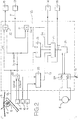
- Figure 2 is a block electrical diagram of the device of Figure 1.
- With reference to Figure 1, a strip S is shown advancing in the direction of the arrow f from a first stand of rolls 1 of a rolling mill to a second stand of rolls 2. Intermediate the stands of rolls, beneath the strip S, is a strip tensioning device (looper) according to the invention, generally indicated L. This device comprises a tensioning arm 3 pivotable about an axis parallel to the strip S and perpendicular to the direction of advance f of the strip. The pivot axis of the tensioning arm 3 is shown in Figure 1 by the intersection between the horizontal plane O and the vertical plane V.
- The tensioning arm 3 carries at one end a load cell 5 of conventional type, for example of the magnetostriction effect type, which cooperates with a
roller 4 kept in contact with the lower face of the strip S and able to move solely along a circular arc β. - In operation, as the tension to which the strip S is subject varies, the force exerted by the
roller 4 on the load cell 5 varies. - The tensioning arm 3 may be rotated about the pivot axis defined above by means of an
electric motor 6 for example of the direct current type, and a pair ofbevel gears 7. The shaft 6a of theelectric motor 6 is coupled to the input shaft of an angular position electric transducer 8 through areduction gear 9. The transducer 8 is preferably a rotary electromagnet analogue transducer of the known type commonly termed a resolver and outputs, as will be clarified below, electrical signals proportional to sina and cosa, a being the angle between the tensioning arm 3 and the horizontal plane O, as indicated in Figure 1. - On opposite sides of its pivot axis, and preferably at the same distance from the axis, the tensioning arm 3 carries two
accelerometers - The device according to the invention further includes a processing and control unit generally indicated 12 in Figure 1 and illustrated in greater detail in Figure 2.
- This unit is connected to the load cell 5, the transducer 8 and the
accelerometers - The processing and
control unit 12 is also connected to theelectric motor 6. - The
processing unit 12 is also connected to a manuallyoperable input device 13 for providing the unit with an electrical signal indicative of a reference value (nominal value) of the tension or draught of the strip S. This device may 13 be constituted simply by a potentiometer. - To the control and
processing unit 12 there are also connected further manuallyoperable input devices 14 and 15 for providing theunit 12 with electrical signals indicative of couple values proportional to the weight of the strip S and to the weight of the tensioning arm 3 for purposes which will be clarified below. - Finally the processing and
control unit 12 is connected to anoutput device 16, for example a visual display device for providing an indication of the tension or draught effectively acting at any moment on the strip S. - The processing and
control unit 12 is also connected to or is connectible to the mains network through a supply line indicated 17 in the drawings. - As will become apparent from the - description which follows with reference to Figure 2, the processing and
control unit 12 is arranged to regulate the current supplied to theelectric motor 6 in dependence on the signals provided by the load cell 5, the position transducer 8, the signals output by theaccelerometers devices 14 and 15 and the nominal tension or draught input by thedevice 13. The supply current for themotor 6 is adjusted when necessary to modify the position of the tensioning arm 3 and hence the draught of the strip S in order to maintain this tension substantially constant and as equal as possible to the nominal tension or draught. - Before the detailed description of the embodiment of the control and
processing unit 12 illustrated in Figure 2, several theoretical considerations at the root of the invention will be put forward. - The inventors have shown that the component of the force exerted between the strip S and the load cell 5 (through the roller 4) in operation, along the axis X-X, is substantially proportional to the function T sina. cosa m where Tm is the instantaneous tension or draught to which the strip S is subject and a is the angle shown in Figure 1.
- As is immediately seen, the component of this force along the axis X-X is just that component which acts on the tensioning arm 3 and gives rise to a couple about the pivot axis of this arm. This couple, which will be indicated below as QL, is thus also proportional to the function given above and hence may be written:
QL = k.Tm.sina.cosa
in which k is a constant dependant on the geometry of the system shown in Figure 1 and in particular on the distance between the stands of rolls 1, 2 and the length of the tensioning arm 3. By virtue of the arrangement described above, the signal output by the load cell 5 is thus indicative of the couple Q applied by the strip S to the tensioning arm 3 about the pivot axis of the tensioning arm. - The processing and
control unit 12 includes twoanalogue multipliers divider 22. Themultiplier 20 has its inputs connected to the outputs of the position transducer 8. Its inputs are thus fed with signals proportional to the absolute value of sin a and cos a respectively. The signal output by themultiplier 20 is thus proportional to the absolute value of sin α.cos α. This signal is fed to thedivider 22 and to themultiplier 21. This latter is also fed with the signal T representing the reference tension or draught (nominal draught) input for the strip S through theinput device 13. Themultiplier 21 thus outputs a signal QN QN=k'.T.sinα.cosα - The output of the
divider 22 in operation is thus a signal proportional to the ratio
QT/sinα.cosα
and is hence proportional to the effective tension or draught acting on the strip S (measured draught). Thevisual display device 16 thus provides a visual indication of the effective value of the draught measured on the strip. - The signals QL and QN are also fed to an integrating
draught couple regulator 23. This device outputs a couple error signal
- The signal indicative of the couple error is supplied to a first input of a summer 24. This summer is also supplied with the signal QN and the signals output by the
input devices 14 and 15 which, as stated above, represent fixed couple values proportional to the weight of the strip S and the weight of the tensioner 3. - The signals output by the
accelerometers
CJ = (d2α/dt2).J
where t represents time and J is the moment of inertia of the tensioning arm 3 about the pivot axis. - The summing circuit 24 in practice effects the algebraic sum of the reference couple QN of the couple error εC, the inertial couple CJ and the couples due to the weight of the strip and to the weight of the tensioner. The overall couple resulting is equal to the couple which the
motor 6 must supply. This couple, as is known, for a direct current motor with independent, fixed energisation is proportional to the current I which must be supplied to the motor. - In conclusion, the output signal I of the summer 24 is proportional to the current needed for the
electric motor 6 to supply a couple such as to allow, through the tensioner 3, the maintenance of a draught on the strip substantially equal to the nominal value. The signal I is supplied to a current regulatingcircuit 26 of known type which, through a full-wave controlledrectifier 27 regulates the current to theelectric motor 6. - Although reference has been made to the use of only one load cell 5 in the description above, clearly two or more load cells 5 may be used in cooperation with the
roller 4. - Naturally, the principle of the invention remaining the same, the embodiments and details of realisation may be varied widely with respect to those described and illustrated purely by way of non-limiting example without thereby departing from the scope of the present invention.
Claims (9)
characterised in that
Priority Applications (1)
| Application Number | Priority Date | Filing Date | Title |
|---|---|---|---|
| AT85830063T ATE57630T1 (en) | 1984-03-15 | 1985-03-12 | DEVICE FOR ADJUSTING STRIP TENSION IN A HOT ROLLING MILL. |
Applications Claiming Priority (2)
| Application Number | Priority Date | Filing Date | Title |
|---|---|---|---|
| IT2006384 | 1984-03-15 | ||
| IT20063/84A IT1173847B (en) | 1984-03-15 | 1984-03-15 | HOT LAMINATION BELT TYPE REGULATOR |
Publications (3)
| Publication Number | Publication Date |
|---|---|
| EP0161223A2 true EP0161223A2 (en) | 1985-11-13 |
| EP0161223A3 EP0161223A3 (en) | 1987-08-05 |
| EP0161223B1 EP0161223B1 (en) | 1990-10-24 |
Family
ID=11163515
Family Applications (1)
| Application Number | Title | Priority Date | Filing Date |
|---|---|---|---|
| EP85830063A Expired - Lifetime EP0161223B1 (en) | 1984-03-15 | 1985-03-12 | Device for regulating the draught of the strip in a hot rolling mill |
Country Status (5)
| Country | Link |
|---|---|
| EP (1) | EP0161223B1 (en) |
| AT (1) | ATE57630T1 (en) |
| DE (1) | DE3580184D1 (en) |
| ES (1) | ES8602455A1 (en) |
| IT (1) | IT1173847B (en) |
Cited By (2)
| Publication number | Priority date | Publication date | Assignee | Title |
|---|---|---|---|---|
| EP0579854A1 (en) * | 1992-07-22 | 1994-01-26 | Kawasaki Steel Corporation | Strip tension control apparatus |
| EP1211206A2 (en) * | 2000-11-29 | 2002-06-05 | Heidelberger Druckmaschinen Aktiengesellschaft | Method and device for measuring the web tension |
Families Citing this family (1)
| Publication number | Priority date | Publication date | Assignee | Title |
|---|---|---|---|---|
| CN104148386A (en) * | 2014-07-01 | 2014-11-19 | 东北大学 | Hydraulic tension warm-rolling machine |
Citations (6)
| Publication number | Priority date | Publication date | Assignee | Title |
|---|---|---|---|---|
| US3961510A (en) * | 1975-07-11 | 1976-06-08 | Wean United, Inc. | Tension device for a rolling mill and the like |
| JPS54122658A (en) * | 1978-03-16 | 1979-09-22 | Toshiba Corp | Controlling method and apparatus for inter-stand tension of continuous hot rolling mill |
| JPS5586609A (en) * | 1978-12-25 | 1980-06-30 | Toshiba Corp | Tension controller |
| SU755357A1 (en) * | 1978-07-31 | 1980-08-15 | Edgar G Fisher | Looper gear for continuous strip rolling mill |
| JPS5639110A (en) * | 1979-09-04 | 1981-04-14 | Toshiba Corp | Controlling method for electrically driven looper of continuous rolling mill |
| JPS5886919A (en) * | 1981-11-20 | 1983-05-24 | Nippon Kokan Kk <Nkk> | Interstand tension controlling method of continuous rolling mill |
-
1984
- 1984-03-15 IT IT20063/84A patent/IT1173847B/en active
-
1985
- 1985-03-12 EP EP85830063A patent/EP0161223B1/en not_active Expired - Lifetime
- 1985-03-12 AT AT85830063T patent/ATE57630T1/en not_active IP Right Cessation
- 1985-03-12 DE DE8585830063T patent/DE3580184D1/en not_active Expired - Lifetime
- 1985-03-14 ES ES541241A patent/ES8602455A1/en not_active Expired
Patent Citations (6)
| Publication number | Priority date | Publication date | Assignee | Title |
|---|---|---|---|---|
| US3961510A (en) * | 1975-07-11 | 1976-06-08 | Wean United, Inc. | Tension device for a rolling mill and the like |
| JPS54122658A (en) * | 1978-03-16 | 1979-09-22 | Toshiba Corp | Controlling method and apparatus for inter-stand tension of continuous hot rolling mill |
| SU755357A1 (en) * | 1978-07-31 | 1980-08-15 | Edgar G Fisher | Looper gear for continuous strip rolling mill |
| JPS5586609A (en) * | 1978-12-25 | 1980-06-30 | Toshiba Corp | Tension controller |
| JPS5639110A (en) * | 1979-09-04 | 1981-04-14 | Toshiba Corp | Controlling method for electrically driven looper of continuous rolling mill |
| JPS5886919A (en) * | 1981-11-20 | 1983-05-24 | Nippon Kokan Kk <Nkk> | Interstand tension controlling method of continuous rolling mill |
Non-Patent Citations (5)
| Title |
|---|
| PATENT ABSTRACTS OF JAPAN, vol. 3, no. 142 (C-65), 24th November 1979, page 146 C 65; & JP-A-54 122 658 (TOKYO SHIBAURA DENKI K.K.) 22.09.1979 * |
| PATENT ABSTRACTS OF JAPAN, vol. 4, no. 128 (M-31)[610], 9th September 1980; & JP-A-55 086 609 (TOKYO SHIBAURA DENKI K.K.) 30-06-1980 * |
| PATENT ABSTRACTS OF JAPAN, vol. 5, no. 93 (M-74)[765], 17th June 1981; & JP-A-56 039 110 (TOKYO SHIBAURA DENKI K.K.) 14-04-1981 * |
| PATENT ABSTRACTS OF JAPAN, vol. 7, no. 187 (M-236)[1332], 16th August 1983; & JP-A-58 086 919 (NIPPON KOKAN K.K.) 24-05-1983 * |
| SOVIET INVENTIONS ILLUSTRATED, 24th June 1981, week D20, abstract no. 53753, M 21, Derwent Publications Ltd; & SU-A-755 357 (E.G. FISCHER) 20-08-1980 * |
Cited By (4)
| Publication number | Priority date | Publication date | Assignee | Title |
|---|---|---|---|---|
| EP0579854A1 (en) * | 1992-07-22 | 1994-01-26 | Kawasaki Steel Corporation | Strip tension control apparatus |
| EP1211206A2 (en) * | 2000-11-29 | 2002-06-05 | Heidelberger Druckmaschinen Aktiengesellschaft | Method and device for measuring the web tension |
| EP1211206A3 (en) * | 2000-11-29 | 2003-10-15 | Heidelberger Druckmaschinen Aktiengesellschaft | Method and device for measuring the web tension |
| US6752013B2 (en) | 2000-11-29 | 2004-06-22 | Heidelberger Druckmaschinen Ag | Device and method for web tension measurement |
Also Published As
| Publication number | Publication date |
|---|---|
| EP0161223A3 (en) | 1987-08-05 |
| ES541241A0 (en) | 1985-12-16 |
| DE3580184D1 (en) | 1990-11-29 |
| EP0161223B1 (en) | 1990-10-24 |
| ATE57630T1 (en) | 1990-11-15 |
| IT8420063A0 (en) | 1984-03-15 |
| IT1173847B (en) | 1987-06-24 |
| ES8602455A1 (en) | 1985-12-16 |
Similar Documents
| Publication | Publication Date | Title |
|---|---|---|
| US2883895A (en) | Rolling mill thickness control system | |
| EP0161223A2 (en) | Device for regulating the draught of the strip in a hot rolling mill | |
| US3940960A (en) | Interstand tension control method and apparatus for tandem rolling mills | |
| US4760723A (en) | Elongation control system | |
| US4706479A (en) | Tandem rolling control system | |
| US3212310A (en) | Automatic gauge and tension control system | |
| US20020177972A1 (en) | Tension control system for rod and bar mills | |
| US3049950A (en) | Manufacture of metal sheet or strip | |
| US3162069A (en) | Method and apparatus for metal rolling | |
| EP0075961B1 (en) | Control device for a continuous rolling machine | |
| KR900001425A (en) | Cold rolling method of sheet and band | |
| JP2574260Y2 (en) | Tension control device | |
| SU876227A1 (en) | Control device responsive to feeding rolling lubricant to rolls | |
| JPS5522435A (en) | Tension control method of hot strip mill | |
| US3174317A (en) | Gage-control system for strip mill | |
| SU1168906A1 (en) | Device for controlling thickness of film | |
| Moore | High performance control for tandem cold mill main drive systems | |
| JPS58221608A (en) | Continuous rolling looper device | |
| SU854480A1 (en) | Loop holder for continuous hot rolling mill | |
| SU764756A1 (en) | Apparatus for controlling the speed of continuous rollingmill stand | |
| SU854484A1 (en) | Apparatus for regulating strip roughness in rolling mill stand | |
| RU2065790C1 (en) | System of "fine" adjustment of band thickness on rolling mill of continuous cold rolling | |
| JPS5469554A (en) | Controlling method for looper | |
| JPH0516926B2 (en) | ||
| JPS5586616A (en) | Optimizing apparatus for gauge controller |
Legal Events
| Date | Code | Title | Description |
|---|---|---|---|
| PUAI | Public reference made under article 153(3) epc to a published international application that has entered the european phase |
Free format text: ORIGINAL CODE: 0009012 |
|
| AK | Designated contracting states |
Designated state(s): AT BE CH DE FR GB LI LU NL SE |
|
| PUAL | Search report despatched |
Free format text: ORIGINAL CODE: 0009013 |
|
| RHK1 | Main classification (correction) |
Ipc: B21B 37/04 |
|
| AK | Designated contracting states |
Kind code of ref document: A3 Designated state(s): AT BE CH DE FR GB LI LU NL SE |
|
| 17P | Request for examination filed |
Effective date: 19871017 |
|
| 17Q | First examination report despatched |
Effective date: 19880516 |
|
| GRAA | (expected) grant |
Free format text: ORIGINAL CODE: 0009210 |
|
| AK | Designated contracting states |
Kind code of ref document: B1 Designated state(s): AT BE CH DE FR GB LI LU NL SE |
|
| REF | Corresponds to: |
Ref document number: 57630 Country of ref document: AT Date of ref document: 19901115 Kind code of ref document: T |
|
| REF | Corresponds to: |
Ref document number: 3580184 Country of ref document: DE Date of ref document: 19901129 |
|
| ET | Fr: translation filed | ||
| REG | Reference to a national code |
Ref country code: CH Ref legal event code: PFA Free format text: ANSALDO INDUSTRIA S.P.A. |
|
| PLBE | No opposition filed within time limit |
Free format text: ORIGINAL CODE: 0009261 |
|
| STAA | Information on the status of an ep patent application or granted ep patent |
Free format text: STATUS: NO OPPOSITION FILED WITHIN TIME LIMIT |
|
| 26N | No opposition filed | ||
| NLT1 | Nl: modifications of names registered in virtue of documents presented to the patent office pursuant to art. 16 a, paragraph 1 |
Owner name: ANSALDO INDUSTRIA S.P.A. TE GENUA EN INNSE INNOCEN |
|
| REG | Reference to a national code |
Ref country code: CH Ref legal event code: PUE Owner name: ANSALDO INDUSTRIA S.P.A. |
|
| REG | Reference to a national code |
Ref country code: GB Ref legal event code: 732 |
|
| REG | Reference to a national code |
Ref country code: FR Ref legal event code: TP |
|
| NLS | Nl: assignments of ep-patents |
Owner name: ANSALDO INDUSTRIA S.P.A. EN INNSE INNOCENTI ENGINE |
|
| REG | Reference to a national code |
Ref country code: FR Ref legal event code: CD |
|
| PGFP | Annual fee paid to national office [announced via postgrant information from national office to epo] |
Ref country code: CH Payment date: 19940211 Year of fee payment: 10 |
|
| PGFP | Annual fee paid to national office [announced via postgrant information from national office to epo] |
Ref country code: LU Payment date: 19940331 Year of fee payment: 10 |
|
| EPTA | Lu: last paid annual fee | ||
| EAL | Se: european patent in force in sweden |
Ref document number: 85830063.5 |
|
| PG25 | Lapsed in a contracting state [announced via postgrant information from national office to epo] |
Ref country code: LU Free format text: LAPSE BECAUSE OF NON-PAYMENT OF DUE FEES Effective date: 19950312 |
|
| PG25 | Lapsed in a contracting state [announced via postgrant information from national office to epo] |
Ref country code: LI Effective date: 19950331 Ref country code: CH Effective date: 19950331 |
|
| REG | Reference to a national code |
Ref country code: CH Ref legal event code: PL |
|
| PGFP | Annual fee paid to national office [announced via postgrant information from national office to epo] |
Ref country code: SE Payment date: 19970131 Year of fee payment: 13 |
|
| PGFP | Annual fee paid to national office [announced via postgrant information from national office to epo] |
Ref country code: AT Payment date: 19970213 Year of fee payment: 13 |
|
| PGFP | Annual fee paid to national office [announced via postgrant information from national office to epo] |
Ref country code: GB Payment date: 19970220 Year of fee payment: 13 |
|
| PGFP | Annual fee paid to national office [announced via postgrant information from national office to epo] |
Ref country code: DE Payment date: 19970224 Year of fee payment: 13 Ref country code: BE Payment date: 19970224 Year of fee payment: 13 |
|
| PGFP | Annual fee paid to national office [announced via postgrant information from national office to epo] |
Ref country code: NL Payment date: 19970225 Year of fee payment: 13 |
|
| PGFP | Annual fee paid to national office [announced via postgrant information from national office to epo] |
Ref country code: FR Payment date: 19970327 Year of fee payment: 13 |
|
| PG25 | Lapsed in a contracting state [announced via postgrant information from national office to epo] |
Ref country code: GB Free format text: LAPSE BECAUSE OF NON-PAYMENT OF DUE FEES Effective date: 19980312 Ref country code: AT Free format text: LAPSE BECAUSE OF NON-PAYMENT OF DUE FEES Effective date: 19980312 |
|
| PG25 | Lapsed in a contracting state [announced via postgrant information from national office to epo] |
Ref country code: SE Free format text: LAPSE BECAUSE OF NON-PAYMENT OF DUE FEES Effective date: 19980313 |
|
| PG25 | Lapsed in a contracting state [announced via postgrant information from national office to epo] |
Ref country code: FR Free format text: THE PATENT HAS BEEN ANNULLED BY A DECISION OF A NATIONAL AUTHORITY Effective date: 19980331 Ref country code: BE Free format text: LAPSE BECAUSE OF NON-PAYMENT OF DUE FEES Effective date: 19980331 |
|
| BERE | Be: lapsed |
Owner name: INNSE INNOCENTI ENGINEERING S.P.A. Effective date: 19980331 Owner name: ANSALDO INDUSTRIA S.P.A. Effective date: 19980331 |
|
| PG25 | Lapsed in a contracting state [announced via postgrant information from national office to epo] |
Ref country code: NL Free format text: LAPSE BECAUSE OF NON-PAYMENT OF DUE FEES Effective date: 19981001 |
|
| GBPC | Gb: european patent ceased through non-payment of renewal fee |
Effective date: 19980312 |
|
| NLV4 | Nl: lapsed or anulled due to non-payment of the annual fee |
Effective date: 19981001 |
|
| PG25 | Lapsed in a contracting state [announced via postgrant information from national office to epo] |
Ref country code: DE Free format text: LAPSE BECAUSE OF NON-PAYMENT OF DUE FEES Effective date: 19981201 |
|
| EUG | Se: european patent has lapsed |
Ref document number: 85830063.5 |
|
| REG | Reference to a national code |
Ref country code: FR Ref legal event code: ST |