EP0579854A1 - Strip tension control apparatus - Google Patents
Strip tension control apparatus Download PDFInfo
- Publication number
- EP0579854A1 EP0579854A1 EP92112605A EP92112605A EP0579854A1 EP 0579854 A1 EP0579854 A1 EP 0579854A1 EP 92112605 A EP92112605 A EP 92112605A EP 92112605 A EP92112605 A EP 92112605A EP 0579854 A1 EP0579854 A1 EP 0579854A1
- Authority
- EP
- European Patent Office
- Prior art keywords
- tension
- arm
- strip
- torque
- angle
- Prior art date
- Legal status (The legal status is an assumption and is not a legal conclusion. Google has not performed a legal analysis and makes no representation as to the accuracy of the status listed.)
- Granted
Links
Images
Classifications
-
- B—PERFORMING OPERATIONS; TRANSPORTING
- B65—CONVEYING; PACKING; STORING; HANDLING THIN OR FILAMENTARY MATERIAL
- B65H—HANDLING THIN OR FILAMENTARY MATERIAL, e.g. SHEETS, WEBS, CABLES
- B65H23/00—Registering, tensioning, smoothing or guiding webs
- B65H23/04—Registering, tensioning, smoothing or guiding webs longitudinally
- B65H23/044—Sensing web tension
-
- B—PERFORMING OPERATIONS; TRANSPORTING
- B21—MECHANICAL METAL-WORKING WITHOUT ESSENTIALLY REMOVING MATERIAL; PUNCHING METAL
- B21B—ROLLING OF METAL
- B21B37/00—Control devices or methods specially adapted for metal-rolling mills or the work produced thereby
- B21B37/48—Tension control; Compression control
- B21B37/50—Tension control; Compression control by looper control
-
- B—PERFORMING OPERATIONS; TRANSPORTING
- B21—MECHANICAL METAL-WORKING WITHOUT ESSENTIALLY REMOVING MATERIAL; PUNCHING METAL
- B21B—ROLLING OF METAL
- B21B41/00—Guiding, conveying, or accumulating easily-flexible work, e.g. wire, sheet metal bands, in loops or curves; Loop lifters
- B21B41/12—Arrangements of interest only with respect to provision for indicating or controlling operations
-
- B—PERFORMING OPERATIONS; TRANSPORTING
- B65—CONVEYING; PACKING; STORING; HANDLING THIN OR FILAMENTARY MATERIAL
- B65H—HANDLING THIN OR FILAMENTARY MATERIAL, e.g. SHEETS, WEBS, CABLES
- B65H23/00—Registering, tensioning, smoothing or guiding webs
- B65H23/04—Registering, tensioning, smoothing or guiding webs longitudinally
- B65H23/048—Registering, tensioning, smoothing or guiding webs longitudinally by positively actuated movable bars or rollers
-
- B—PERFORMING OPERATIONS; TRANSPORTING
- B65—CONVEYING; PACKING; STORING; HANDLING THIN OR FILAMENTARY MATERIAL
- B65H—HANDLING THIN OR FILAMENTARY MATERIAL, e.g. SHEETS, WEBS, CABLES
- B65H23/00—Registering, tensioning, smoothing or guiding webs
- B65H23/04—Registering, tensioning, smoothing or guiding webs longitudinally
- B65H23/16—Registering, tensioning, smoothing or guiding webs longitudinally by weighted or spring-pressed movable bars or rollers
-
- B—PERFORMING OPERATIONS; TRANSPORTING
- B65—CONVEYING; PACKING; STORING; HANDLING THIN OR FILAMENTARY MATERIAL
- B65H—HANDLING THIN OR FILAMENTARY MATERIAL, e.g. SHEETS, WEBS, CABLES
- B65H23/00—Registering, tensioning, smoothing or guiding webs
- B65H23/04—Registering, tensioning, smoothing or guiding webs longitudinally
- B65H23/18—Registering, tensioning, smoothing or guiding webs longitudinally by controlling or regulating the web-advancing mechanism, e.g. mechanism acting on the running web
- B65H23/188—Registering, tensioning, smoothing or guiding webs longitudinally by controlling or regulating the web-advancing mechanism, e.g. mechanism acting on the running web in connection with running-web
- B65H23/1888—Registering, tensioning, smoothing or guiding webs longitudinally by controlling or regulating the web-advancing mechanism, e.g. mechanism acting on the running web in connection with running-web and controlling web tension
-
- B—PERFORMING OPERATIONS; TRANSPORTING
- B65—CONVEYING; PACKING; STORING; HANDLING THIN OR FILAMENTARY MATERIAL
- B65H—HANDLING THIN OR FILAMENTARY MATERIAL, e.g. SHEETS, WEBS, CABLES
- B65H2511/00—Dimensions; Position; Numbers; Identification; Occurrences
- B65H2511/10—Size; Dimensions
- B65H2511/11—Length
- B65H2511/112—Length of a loop, e.g. a free loop or a loop of dancer rollers
-
- B—PERFORMING OPERATIONS; TRANSPORTING
- B65—CONVEYING; PACKING; STORING; HANDLING THIN OR FILAMENTARY MATERIAL
- B65H—HANDLING THIN OR FILAMENTARY MATERIAL, e.g. SHEETS, WEBS, CABLES
- B65H2513/00—Dynamic entities; Timing aspects
- B65H2513/10—Speed
Definitions
- the present invention relates to a strip tension control apparatus for controlling the tension of a strip by threading the strip between a transportation roll and a movable transportation roll and moving the movable transportation roll.
- the apparatus is adapted for maintaining a given strip tension in a process line for rolling or the like.
- the process line is provided with a looper.
- the prior art apparatus includes a dancer roll disposed in the central section, whereby the transmission of the variation in tension is deterred to apply a fixed tension to the strips.
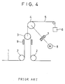
- the prior art tension control apparatus having the dancer roll is constructed in the manner shown in Fig. 4.
- a strip 1 is passed from one transportation roll 2 to the other transportation roll 2 via a dancer roll 3.
- the dancer roll 3 is linked to a wind-up drum 4 and a counterweight 6 by means of a wire 5, and the drum 4 is connected to a motor 8 through a speed reducer 7.
- the motor 8 causes the speed reducer 7 to rotate the wind-up drum 4, thereby moving the dancer roll 3 up and down.
- the tension of the strip 1 is controlled by regulating the torque of the motor.
- Guide means 9 is used to fix the direction of action of the dancer roll 3.
- the conventional prior art tension control apparatus having the dancer roll is helpless against a drastic external variation in tension of the strip in the central section.
- high mechanical resistances are produced between the dancer roll 3 and the guide means 9 and between the wind-up drum 4 and the wire 5.
- the dancer roll 3 is subject to a high moment of inertia during the operation caused by the action of the wind-up roll 4, the motor means 8, and the speed reducer 7, as shown in Fig. 4.
- a backlash of the speed reducer results in a delay in operation or a new variation in tension attributable to the action of the dancer roll.
- the conventional tension control apparatus having the dancer roll is quite helpless against a fine variation in tension due to its great structural mechanical loss, backlash in its mechanical system, and high mechanical resistance.
- the prior art does not permit high- accuracy tension control in response to variations in tension in a continuous operation of the type described above.
- a first object of the invention is to provide a strip tension control apparatus capable of controlling the tension of a strip with high responsiveness and high accuracy despite its drastic external variation.
- a second object of the present invention is to provide a strip tension control apparatus capable of controlling the tension of a strip with good responsiveness and satisfactory accuracy by means of a small-capacity motor, despite a fine variation in the strip tension.
- an apparatus for controlling the tension of a strip by threading the strip between a transportation roll and a movable transportation roll and moving the movable transportation roll.
- a strip tension control apparatus comprises a supporting shaft, rotatably supported by bearing means, and an arm mounted for a swing motion around the supporting shaft and having one end connected to a movable transportation roll.
- a torque around the supporting shaft is generated in the arm by connecting an arm driving motor directly to the supporting shaft, so that a tension is applied to the strip.
- the angle of swing motion of the arm is detected by means of an angle sensor, the tension of the strip is detected by means of a tension sensor, and the torque generated in the arm is corrected in accordance with the detected angle and the detected tension, whereby the tension of the strip is controlled for a target tension.
- the torque of the arm is thus controlled by means of the arm driving motor, and the tension control is effected by turning the movable transportation roll through the medium of the arm.
- the tension control is effected by turning the movable transportation roll through the medium of the arm.
- neither the wind-up drum nor the wire is required, so that the mechanical resistance in the present invention is very small.
- the absence of the wind-up drum and the like in the present invention minimizes the moment of inertia of the machine axis system.
- the arm driving motor is connected directly to the supporting shaft there is no possibility of undergoing a delay in operation or a new variation in tension, which may be caused by backlash when a speed reducer is used.
- the torque is generated in the arm by the following method, as well as by connecting the arm driving motor directly to the supporting shaft.
- the supporting shaft is provided with a counterweight which is adjustable in position with respect to a direction perpendicular to the supporting shaft, and the torque around the supporting shaft is generated in the arm by means of the counterweight.
- the torque to be generated in the arm can be controlled through the control of the motor torque and the adjustment of the counterweight position.
- the angle of swing motion of the arm is detected by means of the angle sensor, and the tension of the strip is detected by means of the tension sensor. Based on the detected angle and the detected tension, the output of the arm driving motor and the position of the counterweight are controlled to control the torque to be generated in the arm, whereby the tension of the strip is controlled at the target tension.
- the torque control by means of the arm driving motor and the torque control through the counterweight position control can be effected in combination with each other.
- the tension of the strip can be controlled with good responsiveness and satisfactory accuracy.
- very effective tension control which is beyond the capability of the conventional prior art dancer roll can be enjoyed such that a fine variation of the strip tension can be eliminated with high accuracy.
- an arm torque to be somewhat fixedly applied depending on the target tension can be obtained through the adjustment of the counterweight position, while an arm torque which rises quickly in response to the variation in tension can be obtained through the torque control by means of the arm driving motor. Accordingly, the motor must only bear the torque corresponding to the variation in tension, so that the motor requires only a small capacity.
- the arm driving motor and a drive unit may be kept to a minimum resulting in an economical advantage.
- reasonable tension control can be ensured such that the torque control is effected through the counterweight position control and the motor can be used for dynamic torque control. In consequence, high- accuracy tension control can be enjoyed.
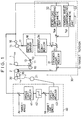
- a first embodiment of the present invention is a strip tension control apparatus constructed in the manner shown in Fig. 1.
- a strip 1 is threaded between transportation rolls 2 and a movable transportation roll 10.
- the apparatus generally comprises a movable transportation roll 10, an arm 11, the supporting shaft 12, an arm driving motor 14, a tension sensor 15, an arm angle sensor 16, a tension control section 30, bridle rolls 20, a bridle roll driving motor 21, and a strip speed control section 40.
- the tension of the strip 1 is controlled through a pivoting movement of the roll 10 about the shaft 12.
- the arm 11, one end of which is supported by the supporting shaft 12, is adapted to swing around the shaft 12, and the movable transportation roll 10 is connected to the other end.
- the supporting shaft 12 is pivotally supported by bearing means 13. Both axial ends of the roll 10 are supported by the arm 11.
- the arm driving motor 14 which is coaxially connected to the supporting shaft 12, is used to generate a torque around the supporting shaft 12, thereby applying a tension to the strip 1.
- the arm angle sensor 16 is used to detect the angle of swing motion of the arm 11 or the rotational angle of the arm driving motor 14. A detected angle ⁇ is entered in the tension control section 30 and the strip speed control section 40.
- the tension sensor 15, which detects the tension of the strip 1, is located very close to the transportation rolls 2.
- the tension control section 30 includes a tension controller 31, a dead load compensating arithmetic unit 32, and a tension angle compensating arithmetic unit 33.
- the tension controller 31 feeds back and comparatively calculates the detected tension T from the tension sensor 15 with respect to the target tension Tr, and delivers the torque control command T1.
- the dead load compensating arithmetic unit 32 is used to compensate the moment of inertia for the dead load of the movable transportation roll 10 and the arm 11 in accordance with the detected angle ⁇ from the angle sensor 16.
- the tension angle compensating arithmetic unit 33 is used to compensate (output torque compensation) a change of the relationship between the strip tension and the output torque of the arm driving motor 14 in accordance with the angle of the arm 11.
- the torque control command T1 is compensated by the respective outputs of the arithmetic units 32 and 33 to become a compensatory torque command T1', which is entered in a current controller 34.
- a current sensor 17 is provided for detecting the current of the motor 14 and feeding it back to the compensatory torque command T1'.
- the torque command T1' or current command fed back in this manner is entered in the current controller 34.
- the current controller 34 is used to enter a command for controlling the input current (torque) of the motor 14 in a motor driver 18 in response to the input current command.
- the tension angle compensating arithmetic unit 33 may carry out output torque compensation in the following manner.
- the output torque is compensated by adding the output torque compensation value Tqt to the tension command.
- the strip speed control section 40 controls the transportation speed of the strip 1 so that it is adjusted to a target speed Vr, and controls the angle ⁇ of the arm 11 for a target angle Ar.
- the speed control section 40 includes an angle controller 41, a dead band generator 42, and a speed controller 43.
- the angle controller 41 compares the target angle Ar and the detected angle ⁇ , and delivers speed modification commands for correcting the angle of the arm 11.
- the dead band generator 42 supplies the speed controller 43 with a speed modification command, among others, of which a fine transient variation of angle is cut off.
- the speed controller 43 controls the speed of the bridle roll driving motor 21, and hence, the rotational speed of the bridle rolls 20 in response to the corrected speed modification command thereby adjusting the transportation speed of the strip so that the angle of the arm is fixed.
- the dead band generator 42 serves to remove a fine transient variation of angle in a speed modification signal for angle correction, since any transient signal variation is harmful.
- the strip 1 is windingly fed through the bridle rolls 20, threaded between the one transportation roll 2, the movable transportation roll 10, the other transportation roll 2, and then delivered to a subsequent stage of flow.
- the tension sensor 15 detects the tension T of the strip 1
- the angle sensor 16 detects the angle ⁇ of the arm 11 fitted with the roll 10, to its horizontal position.
- the detected tension T and the detected angle ⁇ are entered in the tension control section 30, and at the same time the target tension Tr is set in the control section 30.
- the detected tension T is fed back to the target tension Tr, whereupon the torque control command T1 is obtained.
- the detected angle ⁇ is entered in the dead load compensating arithmetic unit 32 and the tension angle compensating arithmetic unit 33, whereupon the units 32 and 33 calculate the torque compensation value Tqs for the dead load and the output torque compensation value Tqt of the tension according to equations (1) and (2). These compensation values are added to the tension command T1 so that the command T1 is compensated to become the compensatory torque command T1'.
- the compensatory torque command T1' is entered as a torque command value, that is, a current command value, in the current controller 34.
- the current controller 34 controls the motor driver 18 thereby regulating the toque of the arm driving motor 14, and hence, the tension of the strip 1.
- the motor current detected by means of the current sensor 17 is fed back to the compensatory torque command T1', and entered in the current controller 34.
- the current controller 34 controls the current supply from the motor driver 18 to the arm driving motor 14, thereby regulating the motor current so that the torque of the motor 14 is adjusted to the command value T1'.
- the speed controller 43 delivers the speed modification command for the line speed Vr.
- the fine transient angle variation is removed by means of the dead band generator 42 to prevent a hindrance.
- the speed correction signal is added to the target line speed Vr and is entered as a speed command in the speed controller 43.
- the speed controller 43 controls the bridle roll driving motor 21, thereby adjusting the transportation speed of the strip and the angle ⁇ of the arm 11 to the target speed Vr and the target angle Ar, respectively.
- Table 1 shows results of comparison between the strip tension control apparatus of the present embodiment and the conventional prior art tension control apparatus using the dancer roll.
- Table 1 No. Items Prior Art First Embodiment Remarks 1 GD2 (Machine axis) Great Small Approx. 1/2 of prior art 2 Mechanical loss Great Small Prior art level: about 50 kg*1 Embodiment: about 2 kg*2 3 Backlash Some None Due to direct connection of motor *1: In strip tension equivalent *2: Frictional torque of bearing means only
- moment of inertia GD2 moment of inertia
- mechanical loss the moment of inertia of the apparatus of the present embodiment
- backlash the moment of inertia of the apparatus of the present embodiment
- the moment of inertia of the apparatus of the present embodiment is about half that of the conventional apparatus.
- the mechanical loss of the apparatus of the first embodiment is about 2 kg in terms of strip tension, as compared with about 50 kg for the conventional apparatus. This is because the apparatus of the present embodiment involves only the frictional torque of the bearing means of the supporting shaft whereas the conventional apparatus is subject to a mechanical loss of the up-and-down motion mechanism for the dancer roll.
- the apparatus of the first embodiment is not. This is because the motor is connected directly to the arm supporting shaft.
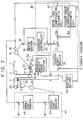
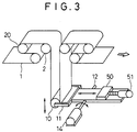
- the second embodiment is a strip tension control apparatus constructed in the manner shown in Fig. 3. As shown in Fig. 3, this strip tension control apparatus, which is constructed substantially in the same manner as the apparatus of the first embodiment, further comprises a counterweight 50, a counterweight position shifting motor 51, and a counterweight position sensor 52.
- the counterweight 50 is arranged on an arm 11 for movement in the longitudinal direction of the arm (or at right angles to a supporting shaft 12). A torque generated in the arm 11 is controlled by adjusting the longitudinal position of the counterweight 50.
- the counterweight 50 is moved by driving the counterweight shifting motor 51.
- the position of the counterweight 50 is detected by means of the counterweight position sensor 52, and is entered in a tension control section 30 (dead load compensating arithmetic unit 32 in the section 30).
- the tension control section 30 includes a tension controller 31, the dead load compensating arithmetic unit 32, a tension angle compensating arithmetic unit 33, and a counterweight position setter 54.
- the tension controller 31 feeds back and comparatively calculates a detected tension T with respect to a target tension Tr, and delivers a torque control command T1.
- the dead load compensating arithmetic unit 32 is used to compensate the moment of inertia for the dead load of a movable transportation roll 10 and the arm 11 in accordance with a detected angle ⁇ from an angle sensor 16.
- the tension angle compensating arithmetic unit 33 is used to compensate (output torque compensation) a change of the relationship between the strip tension and the output torque of an arm driving motor 14 in accordance with the angle of the arm 11.
- the counterweight position setter 54 is used to set the position of the counterweight 50 in accordance with the target tension Tr.
- the counterweight position setter 54 calculates the position St of the counterweight 50 and applies a signal indicative of this position St to a counterweight drive section 53. The calculation of the counterweight position St will be described in detail later.
- the counterweight drive section 53 drives the counterweight position shifting motor 51 to move the counterweight 50 so that the counterweight 50 is located in the position set by means of the setter 54.
- the speed control section 40 includes an angle controller 41 and a speed controller 43.
- the angle controller 41 compares a target angle Ar and the detected angle ⁇ , and delivers a speed modification command for correcting the angle of the arm 11.
- the speed controller 43 controls the speed of the bridle roll driving motor 21, and hence, the rotational speed of the bridle rolls 20 in response to the delivered speed modification command thereby adjusting the transportation speed of the strip so that the angle of the arm is fixed.
- the second embodiment is arranged in the same manner as the first embodiment, so that like reference numerals are used to designate the same parts throughout the drawings.
- the target tension Tr is entered in the counterweight position setter 54, whereupon the setter 54 calculates the position St of the counterweight 50 in accordance with the input target tension Tr, and sets it in the counterweight drive section 53.
- the counterweight position is set in the following manner.
- Tq 2 ⁇ T ⁇ Lr + Wm ⁇ Lm - (Ws ⁇ St + Wr ⁇ Lr + Wf ⁇ Lf) (3)
- Lr is the distance between the central axis of the movable transportation roll 10 and the supporting shaft 12
- Lf is the distance between the center of gravity of the arm 1 and the shaft 12
- Lm is the distance between the center of gravity of the counterweight shifting motor 51 (including the sensor and the like) and the shaft 12
- Wr is the weight of the roll 10
- Ww is the weight of the counterweight 50
- Wf is the weight of the arm 11
- Wm is the weight of the counterweight shifting motor 51 (including the sensor).
- the counterweight shifting motor 51 is located on the opposite side of the supporting shaft 12 with respect to the movable transportation roll 10, so that a torque Wm ⁇ St on the arm 11, which is based on the weight Wm of the motor 51, acts in the same direction as the tension of the strip on the arm 11 as indicated by the first term of equation (3).
- the counterweight position St (2Tref ⁇ Lr + Wm ⁇ Lm) - (Wr ⁇ Lr + Wf ⁇ Lf + Ctq)/Ww (4)
- the movable range (between the maximum and minimum values of the position St) for the counterweight 50 should be established by setting the maximum and minimum values of the necessary target tension Tref for operation at economical values which ensure minimized moment of inertia and required performance in consideration of the torque Ctq of the motor 14 and other constants in equation (4).
- the counterweight position St is determined so that the counterweight 50 is situated as close to the supporting shaft 12 of the arm 11 as possible within a range permitted by the torque CTq of the motor 14. Accordingly, the moment of inertia is lowered so that tension control can be effected with high sensitivity.
- the counterweight 50 is moved to the determined position St to obtain the target tension Tref when the time comes for the tension setting or set tension change.
- the counterweight 50 is moved from its stop position to the position St with a certain speed pattern.
- the target value Tref of the strip tension cannot be attained immediately when the time comes for the tension setting or set tension change, so that the tension control is subject to delay.
- the position of the counterweight 50 is first detected by means of the sensor 52 and fed back to the tension control section 30 whereby the torque Tq of the motor 14 for the target tension value Tref of equation (3) is dynamically calculated. Then, the calculated torque Tq is entered in the current controller 34 so that the torque Tq is applied to the arm 11 by means of the arm driving motor 14.
- the delay of the tension control of the counterweight 50 is compensated so that the tension of the strip 1 can be controlled for the target tension Tref without a delay in the timing for tension setting or set tension change.
- the counterweight 50 is arranged for movement on the arm 11 so that it is adjustable in position with respect to a direction perpendicular to the supporting shaft 12. According to this embodiment, however, the counterweight may be arranged on any suitable means other than the arm which is movable at right angles to the supporting shaft.
- the tension of the strip can be controlled with high responsiveness and high accuracy despite its drastic variation externally introduced into the central section or the like. Since the counterweight is provided on the supporting shaft, moreover, the strip tension can be controlled with good responsiveness and satisfactory accuracy by means of the small-capacity motor, despite a fine variation in the strip tension. In setting the strip tension or changing the set tension, furthermore, the tension can be adjusted to the desired target value. Thus, very effective tension control which is beyond the capability of the conventional dancer roll can be enjoyed. An investigation made by the inventor hereof indicated that the apparatus of the present invention can effect high-accuracy tension control such that the variation in the strip tension can be reduced to about 1/3 as compared with the conventional case.
Landscapes
- Engineering & Computer Science (AREA)
- Mechanical Engineering (AREA)
- Controlling Rewinding, Feeding, Winding, Or Abnormalities Of Webs (AREA)
Abstract
Description
- The present invention relates to a strip tension control apparatus for controlling the tension of a strip by threading the strip between a transportation roll and a movable transportation roll and moving the movable transportation roll. The apparatus is adapted for maintaining a given strip tension in a process line for rolling or the like.
- In order to secure reliable quality of a strip in a process line for metal or nonmetal rolling or the like, it is necessary, in general, to perform a continuous operation in the central section of the line while transporting the strip at a fixed speed and applying a tension to the strip.
- In the supply- or delivery-side section of the process line, limited-length strips are wound off or up in the form of coils. At breaks in the coil jointing or at the time of recoiler change, each strip is accelerated, decelerated or stopped supply- or delivery-side section.
- In order to secure continuous operation in the central section despite such transitory acceleration, deceleration or stopping in the supply- or delivery-side section, the process line is provided with a looper.
- When the looper operates as the strips are decelerated, stopped, or accelerated in the supply- or delivery-side section, however, a variation in tension may be transmitted from the supply- or delivery-side section to the strips in the continuously running central section. This transmission of the variation in tension adversely effects the quality of the strip in the central section and causes the strips to meander, thus possibly breaking the strips.
- To cope with this, a tension control apparatus has been proposed in Japanese Patent Laid-Open No. 1-308347. The prior art apparatus includes a dancer roll disposed in the central section, whereby the transmission of the variation in tension is deterred to apply a fixed tension to the strips.
- The prior art tension control apparatus having the dancer roll is constructed in the manner shown in Fig. 4. In Fig. 4, a
strip 1 is passed from onetransportation roll 2 to theother transportation roll 2 via a dancer roll 3. The dancer roll 3 is linked to a wind-updrum 4 and a counterweight 6 by means of awire 5, and thedrum 4 is connected to amotor 8 through a speed reducer 7. Themotor 8 causes the speed reducer 7 to rotate the wind-updrum 4, thereby moving the dancer roll 3 up and down. The tension of thestrip 1 is controlled by regulating the torque of the motor. Guide means 9 is used to fix the direction of action of the dancer roll 3. - However, the conventional prior art tension control apparatus having the dancer roll is helpless against a drastic external variation in tension of the strip in the central section. In operation, high mechanical resistances are produced between the dancer roll 3 and the guide means 9 and between the wind-up
drum 4 and thewire 5. - The dancer roll 3 is subject to a high moment of inertia during the operation caused by the action of the wind-up
roll 4, the motor means 8, and the speed reducer 7, as shown in Fig. 4. - A backlash of the speed reducer results in a delay in operation or a new variation in tension attributable to the action of the dancer roll.
- Furthermore, the conventional tension control apparatus having the dancer roll is quite helpless against a fine variation in tension due to its great structural mechanical loss, backlash in its mechanical system, and high mechanical resistance. Thus, the prior art does not permit high- accuracy tension control in response to variations in tension in a continuous operation of the type described above.
- Modern steel sheets for use in automobiles and the like are expected to respond quickly to a fine variation in tension, since they are made of very-low-carbon steel, have a small sectional area, and are transported at a super-high speed, as high as 1,000 m/min, as they are processed. There is, therefore, a demonstrated need for advancement in the art of continuous operation strip tension control.
- The present invention has been contrived to solve the problems not addressed by the prior art. A first object of the invention is to provide a strip tension control apparatus capable of controlling the tension of a strip with high responsiveness and high accuracy despite its drastic external variation.
- A second object of the present invention is to provide a strip tension control apparatus capable of controlling the tension of a strip with good responsiveness and satisfactory accuracy by means of a small-capacity motor, despite a fine variation in the strip tension.
- According to the present invention, there is provided an apparatus for controlling the tension of a strip by threading the strip between a transportation roll and a movable transportation roll and moving the movable transportation roll.
- A strip tension control apparatus according to the present invention comprises a supporting shaft, rotatably supported by bearing means, and an arm mounted for a swing motion around the supporting shaft and having one end connected to a movable transportation roll. A torque around the supporting shaft is generated in the arm by connecting an arm driving motor directly to the supporting shaft, so that a tension is applied to the strip. The angle of swing motion of the arm is detected by means of an angle sensor, the tension of the strip is detected by means of a tension sensor, and the torque generated in the arm is corrected in accordance with the detected angle and the detected tension, whereby the tension of the strip is controlled for a target tension.
- The torque of the arm is thus controlled by means of the arm driving motor, and the tension control is effected by turning the movable transportation roll through the medium of the arm. In contrast with the case of the conventional prior art dancer roll, neither the wind-up drum nor the wire is required, so that the mechanical resistance in the present invention is very small. Moreover, the absence of the wind-up drum and the like in the present invention minimizes the moment of inertia of the machine axis system. Furthermore, since the arm driving motor is connected directly to the supporting shaft there is no possibility of undergoing a delay in operation or a new variation in tension, which may be caused by backlash when a speed reducer is used.
- Despite its drastic variation externally introduced into the central section of a process line or the like, the tension of the strip can be controlled with high responsiveness and high accuracy. Thus, very effective tension control which is beyond the capability of the conventional prior art dancer roll can be enjoyed.
- According to the present invention, the torque is generated in the arm by the following method, as well as by connecting the arm driving motor directly to the supporting shaft.
- The supporting shaft is provided with a counterweight which is adjustable in position with respect to a direction perpendicular to the supporting shaft, and the torque around the supporting shaft is generated in the arm by means of the counterweight. The torque to be generated in the arm can be controlled through the control of the motor torque and the adjustment of the counterweight position.
- The angle of swing motion of the arm is detected by means of the angle sensor, and the tension of the strip is detected by means of the tension sensor. Based on the detected angle and the detected tension, the output of the arm driving motor and the position of the counterweight are controlled to control the torque to be generated in the arm, whereby the tension of the strip is controlled at the target tension.
- Accordingly, the torque control by means of the arm driving motor and the torque control through the counterweight position control can be effected in combination with each other.
- Thus, the tension of the strip can be controlled with good responsiveness and satisfactory accuracy. In consequence, very effective tension control which is beyond the capability of the conventional prior art dancer roll can be enjoyed such that a fine variation of the strip tension can be eliminated with high accuracy.
- Since the torque control by means of the arm driving motor and the torque control through the counterweight position control is effected in combination with each other, the torque required of the motor can be reduced.
- For example, an arm torque to be somewhat fixedly applied depending on the target tension can be obtained through the adjustment of the counterweight position, while an arm torque which rises quickly in response to the variation in tension can be obtained through the torque control by means of the arm driving motor. Accordingly, the motor must only bear the torque corresponding to the variation in tension, so that the motor requires only a small capacity.
- Thus, the arm driving motor and a drive unit may be kept to a minimum resulting in an economical advantage. For the initialization of a torque which makes up for the torque of the motor, moreover, reasonable tension control can be ensured such that the torque control is effected through the counterweight position control and the motor can be used for dynamic torque control. In consequence, high- accuracy tension control can be enjoyed.
-
- Fig. 1 is a block diagram showing an outline of a first embodiment of the present invention, with parts in a layout diagram;
- Fig. 2 is a block diagram showing an outline of a second embodiment of the present invention, with parts in a layout diagram;
- Fig. 3 is a perspective view illustrating the principal part of the present invention shown in Fig. 2; and
- Fig. 4 is a layout diagram showing an arrangement of a conventional prior art tension control apparatus using a dancer roll.
- Preferred embodiments of the present invention will now be described in detail with reference to the drawings.
- A first embodiment of the present invention is a strip tension control apparatus constructed in the manner shown in Fig. 1.
- In the strip tension control apparatus of the present invention, as shown in Fig. 1, a
strip 1 is threaded betweentransportation rolls 2 and amovable transportation roll 10. The apparatus generally comprises amovable transportation roll 10, anarm 11, the supportingshaft 12, anarm driving motor 14, atension sensor 15, anarm angle sensor 16, atension control section 30,bridle rolls 20, a bridleroll driving motor 21, and a stripspeed control section 40. The tension of thestrip 1 is controlled through a pivoting movement of theroll 10 about theshaft 12. - The
arm 11, one end of which is supported by the supportingshaft 12, is adapted to swing around theshaft 12, and themovable transportation roll 10 is connected to the other end. The supportingshaft 12 is pivotally supported by bearingmeans 13. Both axial ends of theroll 10 are supported by thearm 11. - The
arm driving motor 14, which is coaxially connected to the supportingshaft 12, is used to generate a torque around the supportingshaft 12, thereby applying a tension to thestrip 1. - The
arm angle sensor 16 is used to detect the angle of swing motion of thearm 11 or the rotational angle of thearm driving motor 14. A detected angle ϑ is entered in thetension control section 30 and the stripspeed control section 40. - The
tension sensor 15, which detects the tension of thestrip 1, is located very close to the transportation rolls 2. Thetension control section 30 includes atension controller 31, a dead load compensatingarithmetic unit 32, and a tension angle compensatingarithmetic unit 33. Thetension controller 31 feeds back and comparatively calculates the detected tension T from thetension sensor 15 with respect to the target tension Tr, and delivers the torque control command T1. The dead load compensatingarithmetic unit 32 is used to compensate the moment of inertia for the dead load of themovable transportation roll 10 and thearm 11 in accordance with the detected angle ϑ from theangle sensor 16. The tension angle compensatingarithmetic unit 33 is used to compensate (output torque compensation) a change of the relationship between the strip tension and the output torque of thearm driving motor 14 in accordance with the angle of thearm 11. - The torque control command T1 is compensated by the respective outputs of the
arithmetic units current controller 34. - A
current sensor 17 is provided for detecting the current of themotor 14 and feeding it back to the compensatory torque command T1'. The torque command T1' or current command fed back in this manner is entered in thecurrent controller 34. Thecurrent controller 34 is used to enter a command for controlling the input current (torque) of themotor 14 in amotor driver 18 in response to the input current command. - As an example, the dead load compensating
arithmetic unit 32 may carry out dead load compensation in the following.
If the dead load of themovable transportation roll 10, thearm 11, the distance between its center of gravity and a supporting point, and the angle of displacement of thearm 11 from its horizontal position (at angle of 0°) are W, Lo, and ϑ, respectively, a torque compensation value Tqs for the dead load is given by

The torque for the dead load is compensated by adding the torque compensation value Tqs to the tension command T1. - As an example, the tension angle compensating
arithmetic unit 33 may carry out output torque compensation in the following manner. - If the strip tension and the distance between the
arm 11 and the supportingshaft 12 are To and Lr, respectively, an output torque compensation value Tqt for the compensation of the output torque based on the angle ϑ is given by

The output torque is compensated by adding the output torque compensation value Tqt to the tension command. - The strip
speed control section 40 controls the transportation speed of thestrip 1 so that it is adjusted to a target speed Vr, and controls the angle ϑ of thearm 11 for a target angle Ar. - The
speed control section 40 includes anangle controller 41, adead band generator 42, and aspeed controller 43. Theangle controller 41 compares the target angle Ar and the detected angle ϑ, and delivers speed modification commands for correcting the angle of thearm 11. Thedead band generator 42 supplies thespeed controller 43 with a speed modification command, among others, of which a fine transient variation of angle is cut off. Thespeed controller 43 controls the speed of the bridleroll driving motor 21, and hence, the rotational speed of the bridle rolls 20 in response to the corrected speed modification command thereby adjusting the transportation speed of the strip so that the angle of the arm is fixed. - The
dead band generator 42 serves to remove a fine transient variation of angle in a speed modification signal for angle correction, since any transient signal variation is harmful. - The following is a description of the operation of the apparatus of the first embodiment. In the tension control apparatus shown in Fig. 1, the
strip 1 is windingly fed through the bridle rolls 20, threaded between the onetransportation roll 2, themovable transportation roll 10, theother transportation roll 2, and then delivered to a subsequent stage of flow. During this process, thetension sensor 15 detects the tension T of thestrip 1, and theangle sensor 16 detects the angle ϑ of thearm 11 fitted with theroll 10, to its horizontal position. The detected tension T and the detected angle ϑ are entered in thetension control section 30, and at the same time the target tension Tr is set in thecontrol section 30. The detected tension T is fed back to the target tension Tr, whereupon the torque control command T1 is obtained. - Meanwhile, the detected angle ϑ is entered in the dead load compensating
arithmetic unit 32 and the tension angle compensatingarithmetic unit 33, whereupon theunits - The compensatory torque command T1' is entered as a torque command value, that is, a current command value, in the
current controller 34. In response to this torque command T1', thecurrent controller 34 controls themotor driver 18 thereby regulating the toque of thearm driving motor 14, and hence, the tension of thestrip 1. In this case, the motor current detected by means of thecurrent sensor 17 is fed back to the compensatory torque command T1', and entered in thecurrent controller 34. In response to this torque command T1', thecurrent controller 34 controls the current supply from themotor driver 18 to thearm driving motor 14, thereby regulating the motor current so that the torque of themotor 14 is adjusted to the command value T1'. - In order to correct the angle by comparing the angle ϑ with the predetermined target angle Ar, the
speed controller 43 delivers the speed modification command for the line speed Vr. In this case, the fine transient angle variation is removed by means of thedead band generator 42 to prevent a hindrance. - Thereafter, the speed correction signal is added to the target line speed Vr and is entered as a speed command in the
speed controller 43. In response to the input speed command, thespeed controller 43 controls the bridleroll driving motor 21, thereby adjusting the transportation speed of the strip and the angle ϑ of thearm 11 to the target speed Vr and the target angle Ar, respectively. - Table 1 shows results of comparison between the strip tension control apparatus of the present embodiment and the conventional prior art tension control apparatus using the dancer roll.
Table 1 No. Items Prior Art First Embodiment Remarks 1 GD² (Machine axis) Great Small Approx. 1/2 of prior art 2 Mechanical loss Great Small Prior art level: about 50 kg*¹ Embodiment: about 2 kg*² 3 Backlash Some None Due to direct connection of motor *1: In strip tension equivalent *2: Frictional torque of bearing means only - In this case, compared factors include moment of inertia GD², mechanical loss, and backlash. The moment of inertia of the apparatus of the present embodiment is about half that of the conventional apparatus. The mechanical loss of the apparatus of the first embodiment is about 2 kg in terms of strip tension, as compared with about 50 kg for the conventional apparatus. This is because the apparatus of the present embodiment involves only the frictional torque of the bearing means of the supporting shaft whereas the conventional apparatus is subject to a mechanical loss of the up-and-down motion mechanism for the dancer roll.
- Although the conventional apparatus is subject to backlash, the apparatus of the first embodiment is not. This is because the motor is connected directly to the arm supporting shaft.
- A second embodiment of the present invention will now be described.
- The second embodiment is a strip tension control apparatus constructed in the manner shown in Fig. 3. As shown in Fig. 3, this strip tension control apparatus, which is constructed substantially in the same manner as the apparatus of the first embodiment, further comprises a
counterweight 50, a counterweightposition shifting motor 51, and acounterweight position sensor 52. - The
counterweight 50 is arranged on anarm 11 for movement in the longitudinal direction of the arm (or at right angles to a supporting shaft 12). A torque generated in thearm 11 is controlled by adjusting the longitudinal position of thecounterweight 50. Thecounterweight 50 is moved by driving thecounterweight shifting motor 51. The position of thecounterweight 50 is detected by means of thecounterweight position sensor 52, and is entered in a tension control section 30 (dead load compensatingarithmetic unit 32 in the section 30). - More specifically, the
tension control section 30 includes atension controller 31, the dead load compensatingarithmetic unit 32, a tension angle compensatingarithmetic unit 33, and acounterweight position setter 54. Thetension controller 31 feeds back and comparatively calculates a detected tension T with respect to a target tension Tr, and delivers a torque control command T1. The dead load compensatingarithmetic unit 32 is used to compensate the moment of inertia for the dead load of amovable transportation roll 10 and thearm 11 in accordance with a detected angle ϑ from anangle sensor 16. The tension angle compensatingarithmetic unit 33 is used to compensate (output torque compensation) a change of the relationship between the strip tension and the output torque of anarm driving motor 14 in accordance with the angle of thearm 11. Thecounterweight position setter 54 is used to set the position of thecounterweight 50 in accordance with the target tension Tr. - In response to the set target tension Tr, the
counterweight position setter 54 calculates the position St of thecounterweight 50 and applies a signal indicative of this position St to acounterweight drive section 53. The calculation of the counterweight position St will be described in detail later. - In response to the input position signal, the
counterweight drive section 53 drives the counterweightposition shifting motor 51 to move thecounterweight 50 so that thecounterweight 50 is located in the position set by means of thesetter 54. - The
speed control section 40 includes anangle controller 41 and aspeed controller 43. Theangle controller 41 compares a target angle Ar and the detected angle ϑ, and delivers a speed modification command for correcting the angle of thearm 11. Thespeed controller 43 controls the speed of the bridleroll driving motor 21, and hence, the rotational speed of the bridle rolls 20 in response to the delivered speed modification command thereby adjusting the transportation speed of the strip so that the angle of the arm is fixed. - For other parts, the second embodiment is arranged in the same manner as the first embodiment, so that like reference numerals are used to designate the same parts throughout the drawings.
- The following is a description of some processes of operation which differentiate the second embodiment from the first embodiment. The target tension Tr is entered in the
counterweight position setter 54, whereupon thesetter 54 calculates the position St of thecounterweight 50 in accordance with the input target tension Tr, and sets it in thecounterweight drive section 53. When the target tension is set, or when the set target tension is changed, the counterweight position is set in the following manner. - If the strip tension is T, a torque Tq required for the
counterweight shifting motor 51 is given by

where Lr is the distance between the central axis of themovable transportation roll 10 and the supportingshaft 12, Lf is the distance between the center of gravity of thearm 1 and theshaft 12, Lm is the distance between the center of gravity of the counterweight shifting motor 51 (including the sensor and the like) and theshaft 12, Wr is the weight of theroll 10, Ww is the weight of thecounterweight 50, Wf is the weight of thearm 11, and Wm is the weight of the counterweight shifting motor 51 (including the sensor). - In the second embodiment, as shown in Figs. 2 and 3, the
counterweight shifting motor 51 is located on the opposite side of the supportingshaft 12 with respect to themovable transportation roll 10, so that a torque Wm·St on thearm 11, which is based on the weight Wm of themotor 51, acts in the same direction as the tension of the strip on thearm 11 as indicated by the first term of equation (3). - If the torque of the
arm driving motor 14 and the target tension are Ctq and Tref, respectively, the counterweight position St, based on equation (3), is given by

The movable range (between the maximum and minimum values of the position St) for thecounterweight 50 should be established by setting the maximum and minimum values of the necessary target tension Tref for operation at economical values which ensure minimized moment of inertia and required performance in consideration of the torque Ctq of themotor 14 and other constants in equation (4). - After the movable range for the
counterweight 50 is established in this manner, the counterweight position St is determined so that thecounterweight 50 is situated as close to the supportingshaft 12 of thearm 11 as possible within a range permitted by the torque CTq of themotor 14. Accordingly, the moment of inertia is lowered so that tension control can be effected with high sensitivity. - After the counterweight position St is determined in this manner, the
counterweight 50 is moved to the determined position St to obtain the target tension Tref when the time comes for the tension setting or set tension change. - In doing this, the
counterweight 50 is moved from its stop position to the position St with a certain speed pattern. Thus, the target value Tref of the strip tension cannot be attained immediately when the time comes for the tension setting or set tension change, so that the tension control is subject to delay. - In order to eliminate this control delay, the position of the
counterweight 50 is first detected by means of thesensor 52 and fed back to thetension control section 30 whereby the torque Tq of themotor 14 for the target tension value Tref of equation (3) is dynamically calculated. Then, the calculated torque Tq is entered in thecurrent controller 34 so that the torque Tq is applied to thearm 11 by means of thearm driving motor 14. - Thus, the delay of the tension control of the
counterweight 50 is compensated so that the tension of thestrip 1 can be controlled for the target tension Tref without a delay in the timing for tension setting or set tension change. - In the second embodiment, the
counterweight 50 is arranged for movement on thearm 11 so that it is adjustable in position with respect to a direction perpendicular to the supportingshaft 12. According to this embodiment, however, the counterweight may be arranged on any suitable means other than the arm which is movable at right angles to the supporting shaft. - According to the present invention, as described herein, the tension of the strip can be controlled with high responsiveness and high accuracy despite its drastic variation externally introduced into the central section or the like. Since the counterweight is provided on the supporting shaft, moreover, the strip tension can be controlled with good responsiveness and satisfactory accuracy by means of the small-capacity motor, despite a fine variation in the strip tension. In setting the strip tension or changing the set tension, furthermore, the tension can be adjusted to the desired target value. Thus, very effective tension control which is beyond the capability of the conventional dancer roll can be enjoyed. An investigation made by the inventor hereof indicated that the apparatus of the present invention can effect high-accuracy tension control such that the variation in the strip tension can be reduced to about 1/3 as compared with the conventional case.
Claims (4)
- An apparatus for controlling the tension of a strip by threading the strip between a transportation roll and a movable transportation roll and moving the movable transportation roll, the strip tension control apparatus comprising:
a supporting shaft rotatably supported by bearing means;
an arm mounted for a swing motion around the supporting shaft and having one end connected to the movable transportation roll;
an arm driving motor connected directly to the supporting shaft and generating a torque in the arm around the supporting shaft thereby applying a tension to the strip;
an arm angle sensor means for detecting the angle of swing motion of the arm;
a tension sensor means for detecting the tension of the strip; and
a tension control means for correcting the torque to be generated in the am in accordance with the detected angle and tension thereby controlling the strip tension for a target tension. - The strip tension control apparatus according to claim 1, further comprising:
a motor torque control means for controlling the torque of the arm driving motor;
a counterweight disposed on the supporting shaft, said counterweight being adjustable in position with respect to a direction perpendicular the supporting shaft and serving to generate the torque in the arm around the supporting shaft, a counterweight position adjusting means for adjusting the perpendicular position of the counterweight to control the torque to be generated in the arm;
and means for controlling the torque to be generated in the arm in accordance with the detected angle and the detected tension under the control of the motor torque control section and the counterweight position adjusting section so that the target tension is attained by the strip tension. - A strip tension control apparatus according to claim 1, wherein said tension control means includes:
a tension controller for feeding back and comparatively calculating the detected tension with respect to the target tension and delivering a torque control command;
a dead load compensating arithmetic unit for compensating the moment of inertia for the dead load of the movable transportation roll and the arm in accordance with the detected angle from the angle sensor;
a tension angle compensating arithmetic means for compensating a change of the relationship between the strip tension and the output torque of the arm driving motor in accordance with the angle of the arm;
and a current controller means for controlling the arm driving motor in accordance with the compensated torque command. - A strip tension control apparatus according to Claim 3, wherein said tension control means includes:
a tension controller means for feeding back and comparatively calculating the detected tension with respect to the target tension and delivering a torque control commend;
a dead load compensating arithmetic unit for compensating the moment of inertia for the dead load of the movable transportation roll and the arm in accordance with the detected angle from the angle sensor;
a tension angle compensating arithmetic means for compensating a change of the relationship between the strip tension and the output torque of the arm driving motor in accordance with the angle of the arm;
and a current controller means for controlling the arm driving motor in accordance with the compensated torque command.
Priority Applications (3)
| Application Number | Priority Date | Filing Date | Title |
|---|---|---|---|
| CA002074434A CA2074434C (en) | 1992-07-22 | 1992-07-22 | Strip tension control apparatus |
| EP92112605A EP0579854B2 (en) | 1992-07-22 | 1992-07-23 | Strip tension control apparatus |
| DE1992627312 DE69227312T3 (en) | 1992-07-23 | 1992-07-23 | Device for regulating the tape tension |
Applications Claiming Priority (2)
| Application Number | Priority Date | Filing Date | Title |
|---|---|---|---|
| CA002074434A CA2074434C (en) | 1992-07-22 | 1992-07-22 | Strip tension control apparatus |
| EP92112605A EP0579854B2 (en) | 1992-07-22 | 1992-07-23 | Strip tension control apparatus |
Publications (3)
| Publication Number | Publication Date |
|---|---|
| EP0579854A1 true EP0579854A1 (en) | 1994-01-26 |
| EP0579854B1 EP0579854B1 (en) | 1998-10-14 |
| EP0579854B2 EP0579854B2 (en) | 2001-10-31 |
Family
ID=25675358
Family Applications (1)
| Application Number | Title | Priority Date | Filing Date |
|---|---|---|---|
| EP92112605A Expired - Lifetime EP0579854B2 (en) | 1992-07-22 | 1992-07-23 | Strip tension control apparatus |
Country Status (2)
| Country | Link |
|---|---|
| EP (1) | EP0579854B2 (en) |
| CA (1) | CA2074434C (en) |
Cited By (9)
| Publication number | Priority date | Publication date | Assignee | Title |
|---|---|---|---|---|
| EP0936275A1 (en) * | 1994-03-02 | 1999-08-18 | Nippon Steel Corporation | Tension control system for continuous annealing apparatus of steel strip |
| WO2003099691A1 (en) * | 2002-05-29 | 2003-12-04 | Fabio Peroni S.P.A. | Device and method for controlling the tension of a weblike material |
| EP1964799A1 (en) * | 2007-02-28 | 2008-09-03 | Applied Materials, Inc. | Web guide control, web processing apparatus and method for operating the same |
| DE102008028113A1 (en) | 2008-06-13 | 2009-12-24 | CSE Seekamp Elektroausrüstungen GmbH & Co. KG | Device for regulating and controlling the band tension in a band device comprises adjusting and changing the force exerted on the band by a dancer roller in an electromagnetic path |
| CN101648219B (en) * | 2008-08-13 | 2011-07-27 | 鞍钢股份有限公司 | cold rolling tension roller speed detection system and control method |
| DE102014103552A1 (en) * | 2014-03-14 | 2015-09-17 | Von Ardenne Gmbh | Transport arrangement, processing arrangement and method for operating a processing arrangement |
| CN106583464A (en) * | 2016-11-11 | 2017-04-26 | 北京首钢冷轧薄板有限公司 | Method and device for optimizing tension of loop |
| CN111392367A (en) * | 2020-04-09 | 2020-07-10 | 东莞市力星激光科技有限公司 | Feeding device of coiling mechanism and laser pipe cutting machine |
| CN117819298A (en) * | 2024-03-06 | 2024-04-05 | 常州宏大智慧科技有限公司 | Wire belt tension control device and wire belt conveying assembly applying same |
Families Citing this family (1)
| Publication number | Priority date | Publication date | Assignee | Title |
|---|---|---|---|---|
| DE102005059822B3 (en) * | 2005-12-14 | 2007-05-31 | Kramer, Carl, Prof. Dr.-Ing. | Device for adjusting the strip tension in a plant for continuous heat treatment of metal strip comprises a pivot arm with a sliding weight and a pivot arm with an auxiliary weight |
Citations (2)
| Publication number | Priority date | Publication date | Assignee | Title |
|---|---|---|---|---|
| DE2452756A1 (en) * | 1973-11-13 | 1975-05-22 | Bobst Fils Sa J | FEED DEVICE FOR A MATERIAL TAPE INTO A PRINTING MACHINE, PREFERABLY MADE OF PAPER OR CARDBOARD |
| EP0161223A2 (en) * | 1984-03-15 | 1985-11-13 | ANSALDO SISTEMI INDUSTRIALI S.p.A. | Device for regulating the draught of the strip in a hot rolling mill |
Family Cites Families (3)
| Publication number | Priority date | Publication date | Assignee | Title |
|---|---|---|---|---|
| AT35781B (en) † | 1908-02-10 | 1909-01-11 | Konrad Bachmann | Molding material for foundry purposes. |
| JPS51127988A (en) † | 1975-04-30 | 1976-11-08 | Ishikawajima Harima Heavy Ind Co Ltd | Tension control device having looper and this looper |
| DE2911881C2 (en) † | 1979-03-26 | 1983-02-24 | Hoesch Werke Ag, 4600 Dortmund | Loop lifter |
-
1992
- 1992-07-22 CA CA002074434A patent/CA2074434C/en not_active Expired - Lifetime
- 1992-07-23 EP EP92112605A patent/EP0579854B2/en not_active Expired - Lifetime
Patent Citations (2)
| Publication number | Priority date | Publication date | Assignee | Title |
|---|---|---|---|---|
| DE2452756A1 (en) * | 1973-11-13 | 1975-05-22 | Bobst Fils Sa J | FEED DEVICE FOR A MATERIAL TAPE INTO A PRINTING MACHINE, PREFERABLY MADE OF PAPER OR CARDBOARD |
| EP0161223A2 (en) * | 1984-03-15 | 1985-11-13 | ANSALDO SISTEMI INDUSTRIALI S.p.A. | Device for regulating the draught of the strip in a hot rolling mill |
Non-Patent Citations (6)
| Title |
|---|
| CURRENT ADVANCES IN MATERIALS AND PROCESSES vol. 4, no. 2, 1991, TOKYO, JP page 598 S. IKEDA ET AL. 'Technology for strip tension control in No. 4 Continuous Annealing Line' * |
| PATENT ABSTRACTS OF JAPAN vol. 10, no. 193 (M-496)8 July 1986 & JP-A-61 037 653 ( KATAOKA KIKAI SEISAKUSHO ) 22 February 1986 * |
| PATENT ABSTRACTS OF JAPAN vol. 12, no. 183 (M-703)28 May 1988 & JP-A-62 296 905 ( TOSHIBA ) 24 December 1987 * |
| PATENT ABSTRACTS OF JAPAN vol. 14, no. 103 (M-941)26 February 1990 & JP-A-1 308 349 ( TOSHIBA ) 13 December 1989 * |
| PATENT ABSTRACTS OF JAPAN vol. 3, no. 59 (C-46)19 May 1979 & JP-A-54 033 852 ( ISHIKAWAJIMA HARIMA JUKOGYO ) 12 March 1979 * |
| PATENT ABSTRACTS OF JAPAN vol. 3, no. 91 (C-54)3 August 1979 & JP-A-54 069 555 ( NIPPON STEEL ) 4 June 1979 * |
Cited By (13)
| Publication number | Priority date | Publication date | Assignee | Title |
|---|---|---|---|---|
| EP0936275A1 (en) * | 1994-03-02 | 1999-08-18 | Nippon Steel Corporation | Tension control system for continuous annealing apparatus of steel strip |
| CN1065000C (en) * | 1994-03-02 | 2001-04-25 | 新日本制铁株式会社 | Continuous annealing apparatus of steel strip and tension control system for the same |
| WO2003099691A1 (en) * | 2002-05-29 | 2003-12-04 | Fabio Peroni S.P.A. | Device and method for controlling the tension of a weblike material |
| US7413139B2 (en) | 2002-05-29 | 2008-08-19 | Fabio Perini S.P.A. | Device and method for controlling the tension of a weblike material |
| EP1964799A1 (en) * | 2007-02-28 | 2008-09-03 | Applied Materials, Inc. | Web guide control, web processing apparatus and method for operating the same |
| DE102008028113A1 (en) | 2008-06-13 | 2009-12-24 | CSE Seekamp Elektroausrüstungen GmbH & Co. KG | Device for regulating and controlling the band tension in a band device comprises adjusting and changing the force exerted on the band by a dancer roller in an electromagnetic path |
| CN101648219B (en) * | 2008-08-13 | 2011-07-27 | 鞍钢股份有限公司 | cold rolling tension roller speed detection system and control method |
| DE102014103552A1 (en) * | 2014-03-14 | 2015-09-17 | Von Ardenne Gmbh | Transport arrangement, processing arrangement and method for operating a processing arrangement |
| DE102014103552B4 (en) | 2014-03-14 | 2019-05-09 | VON ARDENNE Asset GmbH & Co. KG | Processing arrangement and method for coating a tape substrate |
| CN106583464A (en) * | 2016-11-11 | 2017-04-26 | 北京首钢冷轧薄板有限公司 | Method and device for optimizing tension of loop |
| CN111392367A (en) * | 2020-04-09 | 2020-07-10 | 东莞市力星激光科技有限公司 | Feeding device of coiling mechanism and laser pipe cutting machine |
| CN117819298A (en) * | 2024-03-06 | 2024-04-05 | 常州宏大智慧科技有限公司 | Wire belt tension control device and wire belt conveying assembly applying same |
| CN117819298B (en) * | 2024-03-06 | 2024-05-28 | 常州宏大智慧科技有限公司 | Wire belt tension control device and wire belt conveying assembly applying same |
Also Published As
| Publication number | Publication date |
|---|---|
| EP0579854B1 (en) | 1998-10-14 |
| CA2074434A1 (en) | 1994-01-23 |
| EP0579854B2 (en) | 2001-10-31 |
| CA2074434C (en) | 1997-04-15 |
Similar Documents
| Publication | Publication Date | Title |
|---|---|---|
| US5472127A (en) | Strip tension control apparatus | |
| US4998427A (en) | Method for rolling on-gauge head and tail ends of a workpiece | |
| US10576521B2 (en) | Roll feeder and coilded material conveyance method | |
| EP0579854A1 (en) | Strip tension control apparatus | |
| US5495735A (en) | System for controlling strip thickness in rolling mills | |
| JP2003054799A (en) | Continuous form paper traveling tension control device for rotary press | |
| US4760723A (en) | Elongation control system | |
| KR0157135B1 (en) | Apparatus for controlling tension in process line | |
| JPH0819618B2 (en) | Method and apparatus for adjusting the web tension of a textile web | |
| CA2173049C (en) | Method and apparatus for an anticipatory thickness control in foil rolling | |
| KR950011314B1 (en) | Strip tension control apparatus | |
| JPS62280155A (en) | Method of controlling winding tension of film-like material | |
| US4520642A (en) | Control device for continuous rolling machine | |
| JPH06262230A (en) | Method for controlling elongation percentage in skin pass rolling mill | |
| JPH02303625A (en) | Tension controller between hot rolling mill and coiler | |
| JP2749464B2 (en) | Tension control device | |
| EP0075943B2 (en) | Control device for a continuous rolling machine | |
| JP3255785B2 (en) | Thickness control method in tandem rolling mill | |
| JP3018903B2 (en) | Bridle roll operation control method and apparatus | |
| JPH02142610A (en) | Device for automatically controlling sheet thickness of rolling mill | |
| KR100325095B1 (en) | Strip coupling apparatus of whole-length tension threading facility | |
| JPH0551370B2 (en) | ||
| EP0705151B1 (en) | Control of single stand/reversing mills | |
| JPH0217615B2 (en) | ||
| JPH04361819A (en) | Tension control method |
Legal Events
| Date | Code | Title | Description |
|---|---|---|---|
| PUAI | Public reference made under article 153(3) epc to a published international application that has entered the european phase |
Free format text: ORIGINAL CODE: 0009012 |
|
| AK | Designated contracting states |
Kind code of ref document: A1 Designated state(s): DE FR GB |
|
| 17P | Request for examination filed |
Effective date: 19940722 |
|
| 17Q | First examination report despatched |
Effective date: 19951222 |
|
| GRAG | Despatch of communication of intention to grant |
Free format text: ORIGINAL CODE: EPIDOS AGRA |
|
| GRAG | Despatch of communication of intention to grant |
Free format text: ORIGINAL CODE: EPIDOS AGRA |
|
| GRAH | Despatch of communication of intention to grant a patent |
Free format text: ORIGINAL CODE: EPIDOS IGRA |
|
| GRAH | Despatch of communication of intention to grant a patent |
Free format text: ORIGINAL CODE: EPIDOS IGRA |
|
| GRAA | (expected) grant |
Free format text: ORIGINAL CODE: 0009210 |
|
| AK | Designated contracting states |
Kind code of ref document: B1 Designated state(s): DE FR GB |
|
| REF | Corresponds to: |
Ref document number: 69227312 Country of ref document: DE Date of ref document: 19981119 |
|
| ET | Fr: translation filed | ||
| PLBQ | Unpublished change to opponent data |
Free format text: ORIGINAL CODE: EPIDOS OPPO |
|
| PLBI | Opposition filed |
Free format text: ORIGINAL CODE: 0009260 |
|
| PLBF | Reply of patent proprietor to notice(s) of opposition |
Free format text: ORIGINAL CODE: EPIDOS OBSO |
|
| 26 | Opposition filed |
Opponent name: SMS SCHLOEMANN-SIEMAG AKTIENGESELLSCHAFT Effective date: 19990714 |
|
| PLBF | Reply of patent proprietor to notice(s) of opposition |
Free format text: ORIGINAL CODE: EPIDOS OBSO |
|
| PLBF | Reply of patent proprietor to notice(s) of opposition |
Free format text: ORIGINAL CODE: EPIDOS OBSO |
|
| PLAW | Interlocutory decision in opposition |
Free format text: ORIGINAL CODE: EPIDOS IDOP |
|
| PLAW | Interlocutory decision in opposition |
Free format text: ORIGINAL CODE: EPIDOS IDOP |
|
| PUAH | Patent maintained in amended form |
Free format text: ORIGINAL CODE: 0009272 |
|
| STAA | Information on the status of an ep patent application or granted ep patent |
Free format text: STATUS: PATENT MAINTAINED AS AMENDED |
|
| 27A | Patent maintained in amended form |
Effective date: 20011031 |
|
| AK | Designated contracting states |
Kind code of ref document: B2 Designated state(s): DE FR GB |
|
| REG | Reference to a national code |
Ref country code: GB Ref legal event code: IF02 |
|
| ET3 | Fr: translation filed ** decision concerning opposition | ||
| PGFP | Annual fee paid to national office [announced via postgrant information from national office to epo] |
Ref country code: FR Payment date: 20110727 Year of fee payment: 20 |
|
| PGFP | Annual fee paid to national office [announced via postgrant information from national office to epo] |
Ref country code: GB Payment date: 20110720 Year of fee payment: 20 Ref country code: DE Payment date: 20110720 Year of fee payment: 20 |
|
| REG | Reference to a national code |
Ref country code: DE Ref legal event code: R071 Ref document number: 69227312 Country of ref document: DE |
|
| REG | Reference to a national code |
Ref country code: DE Ref legal event code: R071 Ref document number: 69227312 Country of ref document: DE |
|
| REG | Reference to a national code |
Ref country code: GB Ref legal event code: PE20 Expiry date: 20120722 |
|
| PG25 | Lapsed in a contracting state [announced via postgrant information from national office to epo] |
Ref country code: DE Free format text: LAPSE BECAUSE OF EXPIRATION OF PROTECTION Effective date: 20120724 Ref country code: GB Free format text: LAPSE BECAUSE OF EXPIRATION OF PROTECTION Effective date: 20120722 |