EP0161141A1 - Dispositif d'alimentation d'une chambre de combustion pulsatoire en carburant et en comburant - Google Patents
Dispositif d'alimentation d'une chambre de combustion pulsatoire en carburant et en comburant Download PDFInfo
- Publication number
- EP0161141A1 EP0161141A1 EP85400605A EP85400605A EP0161141A1 EP 0161141 A1 EP0161141 A1 EP 0161141A1 EP 85400605 A EP85400605 A EP 85400605A EP 85400605 A EP85400605 A EP 85400605A EP 0161141 A1 EP0161141 A1 EP 0161141A1
- Authority
- EP
- European Patent Office
- Prior art keywords
- oxidant
- fuel
- channels
- injecting
- wall
- Prior art date
- Legal status (The legal status is an assumption and is not a legal conclusion. Google has not performed a legal analysis and makes no representation as to the accuracy of the status listed.)
- Withdrawn
Links
- 238000002485 combustion reaction Methods 0.000 title claims abstract description 20
- 239000000446 fuel Substances 0.000 title claims description 24
- 238000002347 injection Methods 0.000 claims abstract description 28
- 239000007924 injection Substances 0.000 claims abstract description 28
- 239000007800 oxidant agent Substances 0.000 claims description 23
- 230000001590 oxidative effect Effects 0.000 claims description 20
- 239000000203 mixture Substances 0.000 claims description 8
- 239000008188 pellet Substances 0.000 claims description 3
- 239000011810 insulating material Substances 0.000 claims description 2
- 238000011144 upstream manufacturing Methods 0.000 claims description 2
- QVGXLLKOCUKJST-UHFFFAOYSA-N atomic oxygen Chemical compound [O] QVGXLLKOCUKJST-UHFFFAOYSA-N 0.000 abstract 3
- 229910052760 oxygen Inorganic materials 0.000 abstract 3
- 239000001301 oxygen Substances 0.000 abstract 3
- 239000007789 gas Substances 0.000 description 4
- 208000015181 infectious disease Diseases 0.000 description 2
- 239000000463 material Substances 0.000 description 2
- 230000007935 neutral effect Effects 0.000 description 2
- 239000004215 Carbon black (E152) Substances 0.000 description 1
- 230000001133 acceleration Effects 0.000 description 1
- 230000001174 ascending effect Effects 0.000 description 1
- 230000000694 effects Effects 0.000 description 1
- 238000004880 explosion Methods 0.000 description 1
- 230000002349 favourable effect Effects 0.000 description 1
- 238000010438 heat treatment Methods 0.000 description 1
- 229930195733 hydrocarbon Natural products 0.000 description 1
- 150000002430 hydrocarbons Chemical class 0.000 description 1
- 230000000977 initiatory effect Effects 0.000 description 1
- 239000007788 liquid Substances 0.000 description 1
- 230000007774 longterm Effects 0.000 description 1
- 239000002184 metal Substances 0.000 description 1
- 238000000034 method Methods 0.000 description 1
- 230000000284 resting effect Effects 0.000 description 1
- 239000000243 solution Substances 0.000 description 1
- 239000007921 spray Substances 0.000 description 1
Images


Classifications
-
- F—MECHANICAL ENGINEERING; LIGHTING; HEATING; WEAPONS; BLASTING
- F23—COMBUSTION APPARATUS; COMBUSTION PROCESSES
- F23C—METHODS OR APPARATUS FOR COMBUSTION USING FLUID FUEL OR SOLID FUEL SUSPENDED IN A CARRIER GAS OR AIR
- F23C15/00—Apparatus in which combustion takes place in pulses influenced by acoustic resonance in a gas mass
Definitions
- the present invention relates to a device for supplying a pulsating combustion chamber with fuel and with oxidant.
- the pulsed combustion of a mixture of oxidant and fuel in a chamber requires the introduction into this chamber of the mixture intermittently.
- the fuel can be introduced continuously and the oxidant alternatively or the two components can be mixed and the mixture introduced sequentially.
- the device according to the invention makes it possible to inject the fuel in a continuous manner and to inject the oxidant sequentially.
- the choice of continuous injection of fuel raises certain problems which may be incompatible with the long-term use of the pulsating combustion chamber. .
- the propensity for fouling of the supply device is mainly due to the time intervals during which the air is not injected, the combustion of the fuel takes place in the absence of air.
- the air jet introduced is practically vertical. There is therefore a neutral point between the vertical and descending movement of the air and its vertical and ascending movement which precedes the closing of the valves. During this neutral point, which occurs twice per cycle, the walls of the chamber in which the mixing takes place are no longer swept by the gas mixture, which is conducive to fouling.
- the means for injecting the oxidant comprise at least two channels for injecting the oxidant emerging through said valves in an annular manifold which comprises at least one upper wall and one lower wall and at least part of which from the bottom wall has a shape converging towards said intermediate channel, said channels for injecting the oxidant being inclined relative to the axis of the fuel injection means so that the oxidant is imparted a continuously accelerated vortex movement under the combined action of the shape of the manifold and the inclination of said fuel injection channels.
- the fuel injection means consists of an injection head located entirely inside the manifold. This preferably opens out at the upper level of the intermediate chamber.
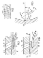
- Figure 1 is a partial sectional view of a device (1) according to the invention. It consists of a body (2) mounted on the neck (3) of a chamber (4) of pulsed combustion.
- the body (2) has two parts, an upper plate (5) and a valve holder part (6). These two parts are parts of revolution, symmetrical about an axis (8).
- the upper plate (5) is fitted into a casing (9) which defines with it a chamber (10) for the admission of air. It has a central bore (13) threaded and bores such as (12).
- the bores (12) are cylindrical and their axes are inclined relative to the axis of revolution (8) and relative to the diametrical planes of the plate as will appear later.
- the plate (5) is provided with a large central bore (20).
- the bottom (21) of this bore has the shape of a surface of revolution (22) whose section through a diametral plane is rounded and of a conical surface (23) in extension of the surface of revolution (22).
- the valve holder part (6) has a central bore (30) comprising a conical part (31), a flared and converging part (32) and a wall (33).
- the curvature of the part (32) is circular and the wall (33) of the bore (30) is vertical in the immediate vicinity (34) of a bore (45).
- the central bore (30) defines with the upper wall of the part (6) a circular step (37) resting on the flat surface (23).
- the valve holder part is fixed to the neck (3) by a series of five bolts such as (40) and comprises a pair of ignition electrodes (41) and (42).
- the device (1) is held in place on the neck (3) by means of threaded tie rods (75) which are screwed into nuts (77) welded on a support place (76) itself welded to, collar (3).
- tie rods (75) which are screwed into nuts (77) welded on a support place (76) itself welded to, collar (3).
- all the parts are metallic, except the valve holder part which is made of a plastic material having good qualities of resistance to thermal transfers by convection.
- the device thus represented operates in the following manner.
- a conventional step of initiating pulsatory combustion is carried out and for this the air is injected through the bores (12) into the manifold (100).
- This manifold (100) is defined by the wall (21) of the bore (20), the walls (31), (32) and (33) of the bore (30) and by the bore (45).
- This injection is made using a fan not shown.
- the combustion is initiated by a high voltage ignition produced by the electrodes (41) and (42).
- the valves (90) close the injection ports (12).
- the fan is used until the pulsating combustion cycle is fully established. In steady state, the electrodes are no longer used.
- the fuel is injected continuously by a nozzle or injection head (115) which is screwed into the bore (11).
- the spray cone of the injection is such that the impact of the drops of fuel takes place mainly below the bore (45), that is to say in the intermediate channel, corresponding to the inside the neck (3).
- the vortex movement of the air is maintained throughout the manifold as well as in the intermediate channel.
- the intermediate channel constitutes the zone for mixing the fuel and the oxidizer, although it is obviously very possible that part of the mixture already takes place in the lower zone of the manifold or, on the contrary, in the combustion (4).
- the injected air always remains in motion even if the vertical component of its speed changes direction since the tangential component will never be zero.
- the lower wall of the collector (100) will always be swept and cooled by a stream of air.
- This favorable effect is further improved by the small volume of the manifold and therefore by the small mass of air capable of being compressed by the ascent of the burnt gases.
- the low volume of the collector is mainly due to the converging shape of its lower wall. This volume can be further reduced by modifying the shape of the upper wall.
- valve holder part was made of a thermally insulating material. This has the effect of limiting the heating of the injection head. But we can also plan to make this piece of metal and interpose between it and the intermediate channel an insulating disc which will then prevent heat transfers upwards, the insulating disc extending over the entire height of the '' bore (45).
- the valve (90) consists of a flat ring (120), deformable, of width greater than the width of the bores (12). It is held in place between the bottom (21) of the bore (20) and the conical wall (31) of the valve-holder part (6) on which it is supported by its outside diameter.
- the height of the circular step (37) is greater than the thickness of the flat ring so that the latter can move between a low position corresponding to the opening of the valve and a high position corresponding to its closing.
- the wall (31) has a conical shape at the level of the ring, the underside of the latter is never completely pressed against the wall (31). The increase in pressure inside the manifold (100) is therefore transmitted to the underside of the ring, which causes the valve to close.
- valves represented in FIGS. 4 and 5 proceed from another principle since they are individual valves (130) produced in the form of pellets (131) which are movable in translation inside centering pads (132 ), (133) and (134) fixed to the plate (5) by being mounted in force in blind bores.
- the wall (31) of the valve-holder part (6) is horizontal opposite the pellets (131).
- a groove (135) is made in the valve-holder part (6) opposite each valve. As is more particularly visible in FIG. 5, the groove is oriented along an axis (150) which is symmetrical with the axis (110) with respect to the diameter (111).
- the bore (12) can be replaced by a series of coaxial bores (140), each having the same orientation as that defined for the axes (12) with reference to FIG. 2. This solution improves the tightness of the valves.
- the bore (45) shown is divergent towards the intermediate channel.
Landscapes
- Engineering & Computer Science (AREA)
- Chemical & Material Sciences (AREA)
- Combustion & Propulsion (AREA)
- Mechanical Engineering (AREA)
- General Engineering & Computer Science (AREA)
- Fluidized-Bed Combustion And Resonant Combustion (AREA)
- Combustion Methods Of Internal-Combustion Engines (AREA)
Applications Claiming Priority (2)
| Application Number | Priority Date | Filing Date | Title |
|---|---|---|---|
| FR8404921A FR2562212B1 (fr) | 1984-03-29 | 1984-03-29 | Dispositif d'alimentation d'une chambre de combustion pulsatoire en carburant et en comburant |
| FR8404921 | 1984-03-29 |
Publications (1)
| Publication Number | Publication Date |
|---|---|
| EP0161141A1 true EP0161141A1 (fr) | 1985-11-13 |
Family
ID=9302597
Family Applications (1)
| Application Number | Title | Priority Date | Filing Date |
|---|---|---|---|
| EP85400605A Withdrawn EP0161141A1 (fr) | 1984-03-29 | 1985-03-28 | Dispositif d'alimentation d'une chambre de combustion pulsatoire en carburant et en comburant |
Country Status (3)
| Country | Link |
|---|---|
| EP (1) | EP0161141A1 (enExample) |
| JP (1) | JPS60253707A (enExample) |
| FR (1) | FR2562212B1 (enExample) |
Citations (7)
| Publication number | Priority date | Publication date | Assignee | Title |
|---|---|---|---|---|
| DE878551C (de) * | 1944-03-14 | 1953-06-05 | Alfred Dipl-Ing Kaercher | Rueckstromsperren an einer mit pulsierender Verbrennung arbeitenden Vorrichtung zur Bereitung und Foerderung von Heizgasen |
| DE970736C (de) * | 1950-04-07 | 1958-10-23 | Kaercher Fa Alfred | Vorrichtung zur Gemisch-Aufbereitung bei Brennern mit schwingender Gas-Saeule |
| GB1187477A (en) * | 1966-08-19 | 1970-04-08 | Crane Fruehauf Trailers Ltd | Vent Check Valve |
| DE2528671A1 (de) * | 1975-06-27 | 1977-01-13 | Kloeckner Humboldt Deutz Ag | Brennkammer fuer fluessig- und gastreibstoffe |
| WO1981001454A1 (en) * | 1979-11-15 | 1981-05-28 | Mareck Bv | Starting method and device for combustion apparatus |
| EP0066203A2 (en) * | 1981-05-20 | 1982-12-08 | Kabushiki Kaisha Toshiba | Pulse combustor |
| WO1984002762A1 (en) * | 1982-12-30 | 1984-07-19 | Mareck Bv | Non-return valve for pulsating burners |
-
1984
- 1984-03-29 FR FR8404921A patent/FR2562212B1/fr not_active Expired
-
1985
- 1985-03-28 JP JP6493385A patent/JPS60253707A/ja active Granted
- 1985-03-28 EP EP85400605A patent/EP0161141A1/fr not_active Withdrawn
Patent Citations (7)
| Publication number | Priority date | Publication date | Assignee | Title |
|---|---|---|---|---|
| DE878551C (de) * | 1944-03-14 | 1953-06-05 | Alfred Dipl-Ing Kaercher | Rueckstromsperren an einer mit pulsierender Verbrennung arbeitenden Vorrichtung zur Bereitung und Foerderung von Heizgasen |
| DE970736C (de) * | 1950-04-07 | 1958-10-23 | Kaercher Fa Alfred | Vorrichtung zur Gemisch-Aufbereitung bei Brennern mit schwingender Gas-Saeule |
| GB1187477A (en) * | 1966-08-19 | 1970-04-08 | Crane Fruehauf Trailers Ltd | Vent Check Valve |
| DE2528671A1 (de) * | 1975-06-27 | 1977-01-13 | Kloeckner Humboldt Deutz Ag | Brennkammer fuer fluessig- und gastreibstoffe |
| WO1981001454A1 (en) * | 1979-11-15 | 1981-05-28 | Mareck Bv | Starting method and device for combustion apparatus |
| EP0066203A2 (en) * | 1981-05-20 | 1982-12-08 | Kabushiki Kaisha Toshiba | Pulse combustor |
| WO1984002762A1 (en) * | 1982-12-30 | 1984-07-19 | Mareck Bv | Non-return valve for pulsating burners |
Also Published As
| Publication number | Publication date |
|---|---|
| FR2562212B1 (fr) | 1988-04-22 |
| JPS60253707A (ja) | 1985-12-14 |
| JPH0478884B2 (enExample) | 1992-12-14 |
| FR2562212A1 (fr) | 1985-10-04 |
Similar Documents
| Publication | Publication Date | Title |
|---|---|---|
| EP0312428B1 (fr) | Dispositif d'injection d'une charge d'hydrocarbures dans un réacteur de craquage catalytique | |
| FR2772118A1 (fr) | Procede de combustion et bruleur a pulverisation de combustible mettant en oeuvre un tel procede | |
| FR2706112A1 (fr) | Injecteurs de plasma à arc en série. | |
| EP0604279A1 (fr) | Injecteur avec paroi poreuse pour chambre de combustion d'une fusée | |
| FR2806450A1 (fr) | Buse d'injection pour une tete de cylindre pour un moteur a combustion interne, et procede pour former un melange carburant/air dans un moteur a combustion interne a injection directe | |
| FR2773851A1 (fr) | Injecteur de carburant pour moteur a combustion interne | |
| WO2007118971A1 (fr) | Bruleur polyvalent a flamme creuse pour hydrocarbures | |
| FR2935774A1 (fr) | Dispositif de remplissage d'une bouteille de gaz | |
| WO1986007434A1 (fr) | Bruleur pour chaudiere a combustible liquide avec circuit de recyclage des gaz de combustion | |
| FR2805196A1 (fr) | Outillage fonctionnant par combustion interne avec vitesse accrue de la propagation du front de flamme dans sa chambre de pre-combustion | |
| EP0161141A1 (fr) | Dispositif d'alimentation d'une chambre de combustion pulsatoire en carburant et en comburant | |
| FR2763638A1 (fr) | Moteur a combustion interne de type a allumage par etincelle avec chambre de sous-combustion | |
| CA1242136A (fr) | Canal intermediaire pour un dispositif d'alimentation d'une chambre de combustion pulsatoire en carburant ou en comburant | |
| FR2528915A1 (fr) | Injecteur de combustible et moteur a combustion interne equipe dudit injecteur | |
| BE529364A (fr) | Procede et appareil pour la fabrication de noir de fumee | |
| EP0204623B1 (fr) | Allumeur destiné aux chargements générateurs de gaz des obus | |
| FR2627228A1 (fr) | Systeme d'injection de carburant pour moteur a deux temps a plusieurs cylindres | |
| FR2732447A1 (fr) | Structure de bruleur du type a orifices pour appareil de combustion de petrole lampant | |
| CH483565A (fr) | Dispositif destiné à organiser la circulation d'un fluide dans un circuit | |
| FR2943733A3 (fr) | Injecteur de carburant et procede de pilotage d'un injecteur de carburant | |
| BE1006302A3 (fr) | Buse, notamment a allumage piezo-electrique, et module d'allumage comportant une telle buse. | |
| FR2716495A1 (fr) | Dispositions permettant d'améliorer le fonctionnement des moteurs Diesel à injection directe. | |
| FR2635169A1 (fr) | Generateur d'air chaud a gaz | |
| FR2490736A1 (fr) | Injecteur de carburant pour moteur a combustion interne | |
| FR2636676A1 (fr) | Dispositif pour l'injection de carburant dans la chambre a explosion d'un moteur a combustion interne a auto-allumage, comprenant un diaphragme regulant et dirigeant les jets de carburants et l'air aspire |
Legal Events
| Date | Code | Title | Description |
|---|---|---|---|
| PUAI | Public reference made under article 153(3) epc to a published international application that has entered the european phase |
Free format text: ORIGINAL CODE: 0009012 |
|
| 17P | Request for examination filed |
Effective date: 19850401 |
|
| AK | Designated contracting states |
Designated state(s): AT BE CH DE GB IT LI LU NL SE |
|
| 17Q | First examination report despatched |
Effective date: 19860828 |
|
| STAA | Information on the status of an ep patent application or granted ep patent |
Free format text: STATUS: THE APPLICATION IS DEEMED TO BE WITHDRAWN |
|
| 18D | Application deemed to be withdrawn |
Effective date: 19870107 |
|
| RIN1 | Information on inventor provided before grant (corrected) |
Inventor name: BADER, JEAN-MARC |