EP0160918A2 - Fixation device for a lighting unit at the bodywork of a motor vehicle - Google Patents
Fixation device for a lighting unit at the bodywork of a motor vehicle Download PDFInfo
- Publication number
- EP0160918A2 EP0160918A2 EP85105236A EP85105236A EP0160918A2 EP 0160918 A2 EP0160918 A2 EP 0160918A2 EP 85105236 A EP85105236 A EP 85105236A EP 85105236 A EP85105236 A EP 85105236A EP 0160918 A2 EP0160918 A2 EP 0160918A2
- Authority
- EP
- European Patent Office
- Prior art keywords
- cavities
- lighting unit
- plastic
- housing
- support frame
- Prior art date
- Legal status (The legal status is an assumption and is not a legal conclusion. Google has not performed a legal analysis and makes no representation as to the accuracy of the status listed.)
- Withdrawn
Links
Images

Classifications
-
- B—PERFORMING OPERATIONS; TRANSPORTING
- B60—VEHICLES IN GENERAL
- B60Q—ARRANGEMENT OF SIGNALLING OR LIGHTING DEVICES, THE MOUNTING OR SUPPORTING THEREOF OR CIRCUITS THEREFOR, FOR VEHICLES IN GENERAL
- B60Q1/00—Arrangement of optical signalling or lighting devices, the mounting or supporting thereof or circuits therefor
- B60Q1/02—Arrangement of optical signalling or lighting devices, the mounting or supporting thereof or circuits therefor the devices being primarily intended to illuminate the way ahead or to illuminate other areas of way or environments
- B60Q1/04—Arrangement of optical signalling or lighting devices, the mounting or supporting thereof or circuits therefor the devices being primarily intended to illuminate the way ahead or to illuminate other areas of way or environments the devices being headlights
- B60Q1/0408—Arrangement of optical signalling or lighting devices, the mounting or supporting thereof or circuits therefor the devices being primarily intended to illuminate the way ahead or to illuminate other areas of way or environments the devices being headlights built into the vehicle body, e.g. details concerning the mounting of the headlamps on the vehicle body
- B60Q1/0441—Arrangement of optical signalling or lighting devices, the mounting or supporting thereof or circuits therefor the devices being primarily intended to illuminate the way ahead or to illuminate other areas of way or environments the devices being headlights built into the vehicle body, e.g. details concerning the mounting of the headlamps on the vehicle body the housing being fastened onto the vehicle body using means other than screws
Landscapes
- Engineering & Computer Science (AREA)
- Mechanical Engineering (AREA)
- Lighting Device Outwards From Vehicle And Optical Signal (AREA)
- Non-Portable Lighting Devices Or Systems Thereof (AREA)
Abstract
Zur Befestigung einer Beleuchtungseinheit an einer Kraftfahrzeugkarosserie ist das Gehäuse (9) oder der Tragrahmen der Beleuchtungseinheit und die Karosserie (15) einerseits mit hinterschnittenen Hohlraumen (13) und andererseits mit in diese Hohlraume hineinragenden Verankerungsvorsprungen (16) versehen. Die Hohlräume (13) sind mit einem aushärtbaren elastischen Kunststoff (20) gefüllt, in dem die Verankerungsvorsprunge (16) eingebettet sind. Dadurch wird eine formschlussige, aber elastische, auch verhältnismäßig große ?Toleranzen? ausgleichende Verbindung swischen der Beleuchtungseinheit und der Karosserie hergestellt.To attach a lighting unit to a motor vehicle body, the housing (9) or the support frame of the lighting unit and the body (15) are provided on the one hand with undercut cavities (13) and on the other hand with anchoring projections (16) projecting into these cavities. The cavities (13) are filled with a hardenable elastic plastic (20) in which the anchoring projections (16) are embedded. This creates a form-fitting, but elastic, even relatively large? Tolerances? compensating connection between the lighting unit and the body.
Description
Die Erfindung bezieht sich auf eine Einrichtung zur Befestigung einer Beleuchtungseinheit an einer Kraftfahrzeugkarosserie, wobei das Gehäuse der Beleuchtungseinheit direkt oder über einen Tragrahmen mit der Karosserie verbunden ist. Der Begriff "Karosserie" umfaßt auch Karosserieteile, wie Front- oder Heckpartien, an denen die Beleuch- tungseinheit anzubringen ist und die an der übrigen Karosserie befestigt werden. Diese Karosserieteile konnen aus Blech bestehen, werden aber in zunehmendem Maße auch aus Kunststoff gefertigt (z.B. "Soft-Nose"), um leichte Unfälle ohne bleibende Verformung überstehen zu können.The invention relates to a device for fastening a lighting unit to a motor vehicle body, the housing of the lighting unit being connected to the body directly or via a support frame. The term "body" includes body parts, such as front and rear sections, where the lighting is doing g seinheit to install and are attached to the rest of the body. These body parts can be made of sheet metal, but are increasingly also made of plastic (eg "soft nose") in order to survive minor accidents without permanent deformation.
Die Befestigung von Scheinwerfern an der Karosserie erfolgt bisher ausschließlich durch Schrauben mit Beilagscheiben und Muttern, sowie zusätzlich durch Federbügel, um eine in bestimmten Grenzen elastische Aufnahme des Scheinwerfers zu erreichen und insbesondere Fahrbahnstöße zu dämpfen, welche die Lebensdauer der Glühlampen erheblich verkürzen. Diese Art der Montage ist verhältnismäßig aufwendig und kann vor allem kaum vollautomatisch durchgeführt werden. Die Schrauben, Scheiben und Muttern sind Losteile, von denen tei der Montage ein nicht unerheblicher Teil verloren geht. Überdies besteht stets die Gefahr, daß bei der Vielzahl von verschiedenartigen Schrauben; die bei der Montage des Fahrzeuges verwendet werden, versehentlich falsche Schrauben benutzt werden, die für die sichere Befestigung der Scheinwerfer nicht geeignet sind.Headlights have so far only been attached to the body by means of screws with washers and nuts, and additionally by spring clips in order to achieve elastic absorption of the headlights within certain limits and in particular to dampen road bumps, which considerably shorten the life of the light bulbs. This type of assembly is relatively complex and, above all, can hardly be carried out fully automatically. The screws, washers and nuts are loose parts, some of which is lost during assembly. In addition, there is always the risk that with the variety of different types of screws; which are used in the assembly of the vehicle, wrong screws are used which are not suitable for the secure mounting of the headlights.
Zur Vermeidung dieser Nachteile ist es bekannt (DE-OS 30 30 427), eine Beleuchtungseinrichtung mittels einer Rastverbindung am Frontteil des Fahrzeuges zu befestigen. Dieser Gedanke läßt sich in der Praxis kaum durchführen, da im Karosseriebau Toleranzen in der Größenordnung von mehreren mm auftreten, die durch eine derartige Rastverbindung nicht überbrückt werden können. Auch die im Betrieb auftretenden Verwindungen der Karosserie lassen eine derartige Rastverbindung problematisch erscheinen. Schließlich ist eine elastische Lagerung über eine derartige Verbindung nur schwer vorstellbar.To avoid these disadvantages, it is known (DE-OS 30 30 427) to fasten a lighting device by means of a latching connection on the front part of the vehicle. This thought can hardly be put into practice since tolerances in the order of magnitude of several mm occur in the body shop, which cannot be bridged by such a snap connection. The torsion of the body that occurs during operation also makes such a locking connection appear problematic. Finally, an elastic mounting via such a connection is difficult to imagine.
Der Erfindung liegt die Aufgabe zugrunde, eine Einrichtung zur Befestigung einer Beleuchtungseinrichtung an einer Kraftfahrzeugkarosserie zu schaffen, mit der die Befestigung voll automatisiert werden kann, die keine Losteile, wie Schrauben, Muttern und Beilagscheiben erfordert, kostengünstig ist, einen großen Toleranzausgleich in jeder Richtung ermöglicht und bewirkt, daß Fahrbahnstöße nur gedämpft auf die Beleuchtungseinrichtung übertragen werden, ohne "tanzendes" Licht zu erzeugen.The invention has for its object to provide a device for fastening a lighting device to a motor vehicle body, with which the fastening can be fully automated, which is inexpensive, no loose parts, such as screws, nuts and washers, allows a large tolerance compensation in every direction and causes road bumps to be transmitted to the lighting device only in a damped manner, without producing "dancing" light.
Diese Aufgabe wird erfindungsgemäß durch die im Kennzeichen des Anspruchs 1 angegebenen Merkmale gelöst.This object is achieved by the features specified in the characterizing part of claim 1.
Bei cer Montage der Beleuchtungseinheit wird ihr Gehäuse bzw. der Tragrahmen in der Karosserie durch übliche Mittel ausgerichtet und lagefixiert, wobei die am einen Teil angebrachten Verankerungsvorsprünge in die hinterschnittenen Hohlräume am anderen Teil hineinragen. Dann wird vollautomatisch mittels üblicher Kunststoff-Spritzpistolen Kunststoff in die Hohlräume eingespritzt, der nach dem Aushärten eine gewisse Elastizität aufweist, welche abstimmbar ist. Besonders vorteilhaft hat sich ein Schaumkunststoff erwiesen, wie er beispielsweise auch beim Einschäumen von Fensterrahmen verwendet wird. Da zwischen der Wand des Hohlraumes und dem in diesen hineinragenden Verankerungsvorsprung in jeder Richtung ein verhältnismäßig großer Abstand sein kann, der von dem Kunststoff ausgefüllt wird, lassen sich Fertigungstoleranzen, die bei Karosserien bis zu 10 mm betragen können, ohne weiteres ausgleichen. Im Reparaturfall kann diese Verbindung auf einfache Weise durch Schmelzen des Kunststoffes mittels einer Thermosonde gelöst werden.When the lighting unit is mounted, its housing or the support frame is aligned and fixed in the body by conventional means, the anchoring projections attached to one part protruding into the undercut cavities on the other part. Then plastic is injected fully automatically into the cavities using conventional plastic spray guns, which after curing has a certain elasticity which can be adjusted. A foam plastic, such as is also used, for example, when foaming window frames, has proven particularly advantageous. Since there can be a relatively large distance between the wall of the cavity and the anchoring protrusion protruding into it, which is made of the plastic manufacturing tolerances, which can be up to 10 mm for car bodies, can be easily compensated for. In the event of a repair, this connection can be released in a simple manner by melting the plastic using a thermal probe.
Die Hohlraume sind vorzugsweise von topfartigen Vertiefungen gebildet, an deren Innenumfangswand radial nach innen vorstehende Vorsprünge, vorzugsweise in Form einer radial nach innen sich erstreckenden Rippe, angeformt sind. Alternativ können cie Hohlräume auch einen trapezförmigen Querschnitt haben.The cavities are preferably formed by cup-like depressions, on the inner circumferential wall of which protrusions protrude radially inwards, preferably in the form of a radially inwardly extending rib. Alternatively, the cavities can also have a trapezoidal cross section.
Die Verankerungsvorsprünge sind vorzugsweise topfförmig und ihr Boden weist eine zentrale Öffnung auf. Diese Ausführung gestattet auf besonders einfache Weise die Herstellung dieser Vorsprünge, wenn es sich bei dem betreffenden Teil um ein Blechteil handelt, da dann die Vorsprünge einfach aus dem Blechteil herausgedrückt werden. Selbstverständlich können diese Vorsprünge auch als eigene Blechpreßteile hergestellt werden, die dann an den betreffenden Stellen an der Karosserie angeschweißt werden.The anchoring projections are preferably cup-shaped and their bottom has a central opening. This design allows the production of these projections in a particularly simple manner if the part in question is a sheet metal part, since the projections are then simply pushed out of the sheet metal part. Of course, these projections can also be manufactured as separate sheet metal pressed parts, which are then welded to the relevant points on the body.
Ausführungsbeispiele der Erfindung werden im folgenden unter Bezugnahme auf die Zeichnungen beschrieben.
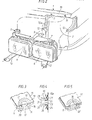
- Fig. 1 zeigt in perspektivischer und teilweise ausein- andergezogener Darstellung den Vorbau einer Kraftfahrzeug-Karosserie mit zwei Beleuchtungseinheiten, von denen die rechte als Tragrahmen-Doppelscheinwerfer und die linke als Gehäusescheinwerfer ausgebildet ist,
- Fig. 2 zeigt den Tragrahmen-Doppelscheinwerfer von Fig. 1 und den benachbarten Teil des Karosserie-Vorbaues in perspektivischer Darstellung und in größerem Maßstab,
- Fig. 3 zeigt eine Befestigungsstelle zwischen dem Scheinwerfergehäuse oder Tragrahmen und der Karosserie gemäß einem ersten Ausführungsbeispiel im Schnitt und in perspektivischer Darstellung, und
- Fig. 4 und 5 zeigen Abwandlungen der in Fig. 2 dargestellten Befestigungsstelle.
- Fig. 1 shows in perspective and partly andergezo g ener representation ausein- the stem of a motor vehicle body with two lighting units, of which the right hand as a support frame twin headlamp and which is formed as a left headlamp housing,
- 2 shows the support frame double headlight from FIG. 1 and the adjacent part of the body stem in perspective and on a larger scale,
- Fig. 3 shows a fastening point between the headlight housing or support frame and the body according to a first embodiment in section and in perspective, and
- 4 and 5 show modifications of the attachment point shown in FIG. 2.
In Fig. 1 ist der Vorbau einer Kraftfahrzeug-Karosserie 1 dargestellt, der Ausschnitte 2 und 3 zur Aufnahme je einer Beleuchtungseinheit aufweist. In Fig. 1 ist die rechte Beleuchtungseinheit 4 als Tragrahmen-Doppelscheinwerfer und die linke Beleuchtungseinheit 5 als Gehäusescheinwerfer ausgebildet. Die Beleuchtungseinheit 4 weist zwei Einbauscheinwerfer 6 auf, die einstellbar in einem Tragrahmen 7 angeordnet ist, der in dem Ausschnitt 2 an der Karosserie 1 befestigt wird. Bei der Beleuchtungseinheit 5 ist der Reflektor zusammen mit der Glühbirne einstellbar in einem Gehäuse 8 angeordnet, das im Ausschnitt 3 an der Karosserie 1 befestigt wird.1 shows the front end of a motor vehicle body 1, which has
Die Anordnung und der Einbau des Tragrahmen-Doppelscheinwerfers 4 in dem Karosserieausschnitt 2 ist in Fig. 2 in größerem Maßstab dargestellt. Der Tragrahmen 7 weist obere Fortsätze 9 und untere Fortsätze 10 auf, an denen der Rahmen 7 im Ausschnitt 2 an der Karosserie 1 befestigt wird. Die Befestigungspunkte an der Karosserie für die Fortsätze 9 sind mit 11 und die Befestigungspunkte für die Fortsätze 10 sind mit 12 bezeichnet.The arrangement and installation of the support frame
Im Gegensatz zu der üblichen Befestigung der Beleuchtungseinheiten an der Karosserie mittels Schrauben und Muttern erfolgt beim Anmeldungsgegenstand diese Verbindung mit Hilfe eines elastischen, aushärtbaren Kunststoffes, wie Polyurethan-Schaumstoff. Beispielsweise Ausbildungen dieser Verbindungen sind in den Figuren 3 bis 5 dargestellt.In contrast to the usual fastening of the lighting units to the body by means of screws and nuts, this connection is made in the subject of the application with the aid of an elastic, hardenable plastic, such as polyurethane foam. For example, configurations of these connections are shown in FIGS. 3 to 5.
Die Befestigung der Fortsätze 9 an den Stellen 11 der Karosserie 1 kann beispielsweise in der in Fig. 3 gezeigten Weise erfolgen. Wie ersichtlich, ist der Fortsatz 9 mit einem im Querschnitt kreisförmigen Hohlraum 13 versehen, an dessen Innenumfangswand eine radial nach innen sich erstreckende Rippe 14 angeformt ist, sodaß ein hinterschnittener Hohlraum gebildet wird. An den Stellen 11 in Fig. 2 ist aus dem Karosserieblech 15 ein topfartiger Vorsprung 16 herausgedrückt, dessen Boden 17 eine zentrale öffnung 18 aufweist und oer in den Hohlraum 13 eingreift. Der Vorsprung 16 ist von einer Ringwulst 19 umgeben, an der die Oberseite des Fortsatzes 9 anliegt. Der Hohlraum 13 und der Innenraum des Vorspronges 16 sind mit einem aushärtenden elastischen Kunststoff 20, beispielsweise Polyurethan-Schaum, ausgefüllt, sodaß der Vorsprung 16 in dem Kunststoff eingebettet ist. Durch die Hinterschneidungen, die einerseits von der Rippe 14 und andererseits von dem Rand des Bodens 17 gebildet werden, entsteht über den Kunststoff 20 eine formschlüssige, jedoch etwas elastische Verbindung zwischen dem Fortsatz 9 und dem Karosserieblech 15.The attachment of the
Die Befestigung der Fortsätze 10 des Tragrahmens 7 an den Stellen 12 der Karosserie kann in der aus Fig. 4 ersichtlichen Weise erfolgen. Das Befestigungsprinzip ist das gleiche wie bei Fig. 3, nur ist hier an dem Karosserieblech 15a ein topfartiger Körper 21 angeschweißt, dessen Boden 22 eine zentrale öffnung 23 aufweist und der mit einer Ringwulst 24 versehen ist, an der der Fortsatz 10 mit seiner Rückseite anliegt. Der Fortsatz 10 ist ähnlich wie beim Ausführungsbeispiel gemäß Fig. 3 mit einem Hohlraum 25 versehen, in den eine Rippe 27 hineinragt und dessen Boden 28 eine öffnung 29 aufweist. Der Hohlraum 25 und auch der Innenraum des topfartigen Körpers 21 ist mit aushärtendem elastischen Kunststoff 26 gefüllt, welcher aufgrund der Hinterschneidungen, gebildet durch die Rippe 27 im Hohlraum 25 und den Rand des Bodens 22 des topfartigen Körpers 21, eine formschlüssige, jedoch elastische Verbindung zwischen dem Fortsatz 10 und dem Karosserieblech 15a herstellt.The attachment of the
Bei der Montage der Beleuchtungseinheit 4 wird diese mittels einer Montagehilfslehre im Ausschnitt 2 der Karosserie 1 lagemäßig fixiert, wobei die topfartigen Vorsprünge 16 in den Hohlräumen 13 und die topfartigen Körper 21 in den Hohlräumen 25 zu liegen kommen. Dann wird mittels einer Spritzpistole Kunststoff einerseits durch die Vorsprunge 16 unc die öffnungen 18 in die Hohlräume 13 und andererseits durch die Öffnungen 29 in die Hohlräume 25 und durch die öffnungen 23 in die Innenräume der topf artigen Körper 21 eingespritzt, bis diese vollständig mit Kunststoff gefüllt sind, wie dies aus Figuren 3 und 4 ersichtlich ist. Nach dem Aushärten des Kunststoffes ist der Tragrahmen 7 mit den Scheinwerfern 6 fest, aber elastisch mit der Karosserie 1 verbunden. Dann kann die Montagehilfslehre abgenommen werden.When the
Das Ausführungsbeispiel gemäß Fig. 5 entspricht weitgehend dem Ausführungsbeispiel gemäß Fig. 3, mit dem Unterschied, daß der Hohlraum 13' einen trapezförmigen Querschnitt hat und dadurch hinterschnitten ist, sodaß die Rippe 14 von Fig. 3 entfallen kann.The embodiment according to FIG. 5 largely corresponds to the embodiment according to FIG. 3, with the difference that the cavity 13 'has a trapezoidal cross section and is thereby undercut, so that the
In den dargestellten Ausführungsbeispielen ist der Tragrahmen 7 aus Kunststoff und das Karosserieteil aus Blech. Es können jedoch auch beide Teile aus dem gleichen Material oder das Karosserieteil aus Kunststoff und der Tragrahmen aus Blech bestehen.In the illustrated embodiments, the
Die Befestigung der Beleuchtungseinheit 5, also eines Gehausescheinwerfers, in dem Ausschnitt 3 des Karosserievorbajes kann in der gleichen Weise wie vorstehend ir Zusammenhang mit der Befestigung der Beleuchtungseinheit 4 beschrieben, durchgeführt werden. Dabei ist das Scheinwerfergehäuse 8 mit hinterschnittenen Hohlräumen 13 bzw. 25 versehen, in welche die topfartigen Vorsprünge 16 bzw. 21 eingreifen. Welche der Ausführungen von Fig. 3 und 4 verwendet wird, hängt von der Zugänglichkeit für die Spritzpistolen ab.The
Selbstverständlich sind viele Abwandlungen der dargestellten Ausführungsbeispiele denkbar, ohne den Rahmen der Erfindung zu verlassen. Wesentlich für die Erfindung ist lediglich, daß die Querschnitte der Hohlräume und die in diese hineinragenden Vorsprünge derart ausgebildet sind, daß durch den eingespritzten und erhärteten Kunststoff eine formschlussige Verbindung zwischen den Teilen hergestellt wird.Of course, many modifications of the illustrated exemplary embodiments are conceivable without departing from the scope of the invention. It is only essential for the invention that the cross sections of the cavities and the projections projecting into them are designed such that a positive connection between the parts is produced by the injected and hardened plastic.
Claims (5)
dadurch gekennzeichnet, daß das Gehäuse (8) oder der Tragrahmen (7) der Beleuchtungseinheit (5 bzw. 4) und die Karosserie (1) einerseits hinterschnittene Hohlräume (13, 25) und andererseits in die Hohlräume (13, 25) hineinragende Verankerungsvorsprünge (16, 21) aufweist und die Hohlräume (13, 25) mit einem aushärtbaren elastischen Kunststoff (20 bzw. 26) gefüllt sind, in den die Verankerungsvorsprünge (16, 21) eingebettet sind.1. Device for fastening a lighting unit to a motor vehicle body, the housing of the lighting unit being connected to the body directly or via a supporting frame,
characterized in that the housing (8) or the support frame (7) of the lighting unit (5 or 4) and the body (1) on the one hand have undercut cavities (13, 25) and on the other hand anchoring protrusions (13, 25) projecting into the cavities (13, 25) 16, 21) and the cavities (13, 25) are filled with a hardenable elastic plastic (20 or 26) in which the anchoring projections (16, 21) are embedded.
Applications Claiming Priority (2)
| Application Number | Priority Date | Filing Date | Title |
|---|---|---|---|
| DE3417041 | 1984-05-09 | ||
| DE3417041A DE3417041C2 (en) | 1984-05-09 | 1984-05-09 | Device for fastening a lighting unit to a motor vehicle body |
Publications (2)
| Publication Number | Publication Date |
|---|---|
| EP0160918A2 true EP0160918A2 (en) | 1985-11-13 |
| EP0160918A3 EP0160918A3 (en) | 1987-12-09 |
Family
ID=6235284
Family Applications (1)
| Application Number | Title | Priority Date | Filing Date |
|---|---|---|---|
| EP85105236A Withdrawn EP0160918A3 (en) | 1984-05-09 | 1985-04-30 | Fixation device for a lighting unit at the bodywork of a motor vehicle |
Country Status (4)
| Country | Link |
|---|---|
| US (1) | US4636921A (en) |
| EP (1) | EP0160918A3 (en) |
| JP (1) | JPS616041A (en) |
| DE (1) | DE3417041C2 (en) |
Cited By (7)
| Publication number | Priority date | Publication date | Assignee | Title |
|---|---|---|---|---|
| FR2710592A1 (en) * | 1993-09-30 | 1995-04-07 | Peugeot | Motor vehicle headlamp equipped with elastic stops |
| EP0679552A2 (en) * | 1994-04-28 | 1995-11-02 | Hella KG Hueck & Co. | Cover for lighting unit with reflectors |
| EP0679551A2 (en) * | 1994-04-28 | 1995-11-02 | Hella KG Hueck & Co. | Lighting unit for vehicle |
| FR2719359A1 (en) * | 1994-04-28 | 1995-11-03 | Hella Kg Hueck & Co | Closing part of a housing of an optical unit for vehicles, containing reflectors. |
| WO2004065171A1 (en) * | 2003-01-21 | 2004-08-05 | Schefenacker Vision Systems | Fixing device for elements of a motor vehicle, in particular the lights thereof |
| FR3015003A1 (en) * | 2013-12-13 | 2015-06-19 | Peugeot Citroen Automobiles Sa | MOTOR VEHICLE PROJECTOR WITHOUT ICE |
| FR3026688A1 (en) * | 2014-10-06 | 2016-04-08 | Peugeot Citroen Automobiles Sa | ICE-FREE VEHICLE PROJECTOR |
Families Citing this family (10)
| Publication number | Priority date | Publication date | Assignee | Title |
|---|---|---|---|---|
| DE3542457A1 (en) * | 1985-11-30 | 1987-06-04 | Bosch Gmbh Robert | HEADLIGHTS FOR VEHICLES, ESPECIALLY FOR MOTOR VEHICLES |
| SE9604293D0 (en) * | 1996-11-22 | 1996-11-22 | Lennart Gaelliner | Strålkastararrangemang |
| US6257749B1 (en) * | 1999-05-12 | 2001-07-10 | Honda Giken Kogyo Kabushiki Kaisha | Vehicle lamp housing having multiple mounting means, and method of using same |
| DE10309087A1 (en) * | 2003-03-03 | 2004-09-23 | Hella Kg Hueck & Co. | Fixing device for automobile headlamp unit using rotatable spindle screws and spindle nuts secured to headlamp housing via quick-fit couplings |
| DE10314091A1 (en) * | 2003-03-28 | 2004-10-14 | Adam Opel Ag | Headlight housing and vehicle body with a receptacle therefor |
| JP3843968B2 (en) * | 2003-06-24 | 2006-11-08 | 日産自動車株式会社 | Headlamp body positioning method and body positioning structure |
| KR100514480B1 (en) * | 2003-09-01 | 2005-09-14 | 기아자동차주식회사 | Mounting structure between head lamp and fender of vehicle |
| DE102005009915B4 (en) * | 2005-03-01 | 2008-08-28 | Daimler Ag | Bow area of a motor car |
| DE102013008908A1 (en) * | 2013-05-25 | 2014-11-27 | Audi Ag | Motor vehicle lamp, motor vehicle headlight and system of motor vehicle lamp or motor vehicle headlight and component for a motor vehicle |
| DE102018129034B4 (en) | 2018-11-19 | 2022-03-17 | Dr. Ing. H.C. F. Porsche Aktiengesellschaft | Front body structure for a motor vehicle |
Citations (4)
| Publication number | Priority date | Publication date | Assignee | Title |
|---|---|---|---|---|
| US3902949A (en) * | 1966-08-15 | 1975-09-02 | Pressed Steel Fisher Ltd | Method of bonding the workpieces together with hot-melt adhesive |
| DE2416898A1 (en) * | 1974-04-06 | 1975-10-09 | Gmoehling Leichtmetall | Fastening for sheet metal edges - uses undercut in the profiled section and synthetic cement |
| JPS5441559A (en) * | 1977-09-08 | 1979-04-02 | Hattori Riyousuke | Device of producing channel brush |
| FR2488556A1 (en) * | 1980-08-12 | 1982-02-19 | Bosch Gmbh Robert | Automobile headlights recessed into front bumper - has each headlight snap-fitted into respective fixing socket and provides pivoting action for entire unit |
Family Cites Families (4)
| Publication number | Priority date | Publication date | Assignee | Title |
|---|---|---|---|---|
| US3065340A (en) * | 1960-04-11 | 1962-11-20 | Gen Motors Corp | Shock absorbing lamp mounting |
| SE402431B (en) * | 1976-07-21 | 1978-07-03 | Saab Scania Ab | LIGHT UNIT AT THE FRONT CORNER OF A VEHICLE |
| DE2732895C3 (en) * | 1977-07-21 | 1981-09-10 | Ford-Werke Ag, 5000 Koeln | Headlights, in particular for motor vehicles |
| US4482690A (en) * | 1984-02-09 | 1984-11-13 | Air Products And Chemicals, Inc. | Process for the production of polyurethane urea elastomers |
-
1984
- 1984-05-09 DE DE3417041A patent/DE3417041C2/en not_active Expired
-
1985
- 1985-04-30 EP EP85105236A patent/EP0160918A3/en not_active Withdrawn
- 1985-05-07 JP JP60097656A patent/JPS616041A/en active Pending
- 1985-05-08 US US06/731,964 patent/US4636921A/en not_active Expired - Fee Related
Patent Citations (4)
| Publication number | Priority date | Publication date | Assignee | Title |
|---|---|---|---|---|
| US3902949A (en) * | 1966-08-15 | 1975-09-02 | Pressed Steel Fisher Ltd | Method of bonding the workpieces together with hot-melt adhesive |
| DE2416898A1 (en) * | 1974-04-06 | 1975-10-09 | Gmoehling Leichtmetall | Fastening for sheet metal edges - uses undercut in the profiled section and synthetic cement |
| JPS5441559A (en) * | 1977-09-08 | 1979-04-02 | Hattori Riyousuke | Device of producing channel brush |
| FR2488556A1 (en) * | 1980-08-12 | 1982-02-19 | Bosch Gmbh Robert | Automobile headlights recessed into front bumper - has each headlight snap-fitted into respective fixing socket and provides pivoting action for entire unit |
Non-Patent Citations (1)
| Title |
|---|
| PATENT ABSTRACTS OF JAPAN, Band 3, Nr. 65 (M-61)[118], 6. Juni 1979; & JP - A - 54 41559 (FUJITSU K.K.) 04.04.1979 * |
Cited By (11)
| Publication number | Priority date | Publication date | Assignee | Title |
|---|---|---|---|---|
| FR2710592A1 (en) * | 1993-09-30 | 1995-04-07 | Peugeot | Motor vehicle headlamp equipped with elastic stops |
| EP0679552A2 (en) * | 1994-04-28 | 1995-11-02 | Hella KG Hueck & Co. | Cover for lighting unit with reflectors |
| EP0679551A2 (en) * | 1994-04-28 | 1995-11-02 | Hella KG Hueck & Co. | Lighting unit for vehicle |
| FR2719359A1 (en) * | 1994-04-28 | 1995-11-03 | Hella Kg Hueck & Co | Closing part of a housing of an optical unit for vehicles, containing reflectors. |
| EP0679552A3 (en) * | 1994-04-28 | 1996-05-15 | Hella Kg Hueck & Co | Cover for lighting unit with reflectors. |
| EP0679551A3 (en) * | 1994-04-28 | 1996-05-22 | Hella Kg Hueck & Co | Lighting unit for vehicle. |
| TR28697A (en) * | 1994-04-28 | 1997-01-16 | Hella Kg Hueck & Co | Cover group of a housing body that receives reflectors (reflectors) of a headlight unit for vehicles. |
| ES2120853A1 (en) * | 1994-04-28 | 1998-11-01 | Hella Kg Hueck & Co | Cover part for housing accommodating reflectors for vehicle light unit |
| WO2004065171A1 (en) * | 2003-01-21 | 2004-08-05 | Schefenacker Vision Systems | Fixing device for elements of a motor vehicle, in particular the lights thereof |
| FR3015003A1 (en) * | 2013-12-13 | 2015-06-19 | Peugeot Citroen Automobiles Sa | MOTOR VEHICLE PROJECTOR WITHOUT ICE |
| FR3026688A1 (en) * | 2014-10-06 | 2016-04-08 | Peugeot Citroen Automobiles Sa | ICE-FREE VEHICLE PROJECTOR |
Also Published As
| Publication number | Publication date |
|---|---|
| US4636921A (en) | 1987-01-13 |
| DE3417041A1 (en) | 1985-11-14 |
| JPS616041A (en) | 1986-01-11 |
| DE3417041C2 (en) | 1986-03-20 |
| EP0160918A3 (en) | 1987-12-09 |
Similar Documents
| Publication | Publication Date | Title |
|---|---|---|
| DE3417041C2 (en) | Device for fastening a lighting unit to a motor vehicle body | |
| EP0642206B2 (en) | Support for an electric motor, particularly for a fan of a heating or air conditioning system | |
| DE3030427C2 (en) | ||
| DE19731314A1 (en) | Steering wheel with airbag module | |
| EP1311415B1 (en) | Wiping system for a windscreen of an automobile and method for fixing a windscreen wiping system | |
| DE19741522A1 (en) | Pre-assembled component for car body | |
| WO2015131993A1 (en) | Locking pin for mounting an airbag module on a motor vehicle | |
| WO2016062379A1 (en) | Device for securing a gas generator in an airbag module in an oscillating manner | |
| EP1234728A1 (en) | Bumper system for a motor vehicle | |
| DE102013012227A1 (en) | Lamp i.e. headlight, for mounting on body part i.e. bumper, of motor vehicle, has housing, and guide that is arranged on body part of counterpart for alignment of lamp on body part that is predefined, where guide is arranged at end lens | |
| DE3545141C2 (en) | ||
| DE10220985A1 (en) | Method for precision alignment and assembly of e.g. two motor vehicle body components on assembly part with alignment part to position components at relative tolerance | |
| DE3616694A1 (en) | Lighting device for vehicles, in particular for motor vehicles | |
| DE10147604A1 (en) | Damper for supporting a vehicle shock absorber, comprises an outer housing, a bearing element, and a damper element made of an impact damping material | |
| EP0307687A1 (en) | Connection of two elements, particularly those of the windscreen wiper at a motor vehicle body | |
| EP0857600A1 (en) | Vehicle window, especially for motor vehicles, and method for assembing such a vehicle window | |
| DE10056625A1 (en) | Gas generator for airbag mounted on vehicle steering wheel acts as shock absorber, filter tube having peripheral collar which fits into groove at top of conical spring whose lower end fits over mounting flange | |
| EP1270284A1 (en) | Damper support | |
| DE10023487A1 (en) | Fastening system for plastic cladding component fitted on car comprises profile with integral clip, holder below this having aperture into which replacement clip can be fitted which is retained by flanges above and below holder | |
| EP0326820B1 (en) | Headlamp for vehicles, particularly motor vehicles | |
| DE102007026460A1 (en) | Floor-mounted frame for automotive electronic module has slide-fit socket with locking clip | |
| EP3593035A1 (en) | Lighting device for vehicles and mounting method | |
| EP0743232A2 (en) | Mounting device for the jet holder of a vehicle headlamp washer | |
| DE10019082B4 (en) | Carrier for a device for measuring tire pressure for use in a rim-mounted pneumatic tire and wheel equipped therewith | |
| DE102009058815A1 (en) | Holding device for attachments, particularly for sun visors of vehicle, comprises click-stop unit, which is arranged at retaining plate made of plastic material, by which holding device is locked at latching receptacle |
Legal Events
| Date | Code | Title | Description |
|---|---|---|---|
| PUAI | Public reference made under article 153(3) epc to a published international application that has entered the european phase |
Free format text: ORIGINAL CODE: 0009012 |
|
| AK | Designated contracting states |
Designated state(s): DE FR GB |
|
| PUAL | Search report despatched |
Free format text: ORIGINAL CODE: 0009013 |
|
| AK | Designated contracting states |
Kind code of ref document: A3 Designated state(s): DE FR GB |
|
| STAA | Information on the status of an ep patent application or granted ep patent |
Free format text: STATUS: THE APPLICATION IS DEEMED TO BE WITHDRAWN |
|
| 18D | Application deemed to be withdrawn |
Effective date: 19880610 |
|
| RIN1 | Information on inventor provided before grant (corrected) |
Inventor name: VOLLRATH, JOHANNES |