EP0159484A1 - Adjustable radius apparatus for calibrating ultrasonic transducer array - Google Patents
Adjustable radius apparatus for calibrating ultrasonic transducer array Download PDFInfo
- Publication number
- EP0159484A1 EP0159484A1 EP85101643A EP85101643A EP0159484A1 EP 0159484 A1 EP0159484 A1 EP 0159484A1 EP 85101643 A EP85101643 A EP 85101643A EP 85101643 A EP85101643 A EP 85101643A EP 0159484 A1 EP0159484 A1 EP 0159484A1
- Authority
- EP
- European Patent Office
- Prior art keywords
- transducer array
- calibration apparatus
- calibration
- pendulum arm
- pendulum
- Prior art date
- Legal status (The legal status is an assumption and is not a legal conclusion. Google has not performed a legal analysis and makes no representation as to the accuracy of the status listed.)
- Withdrawn
Links
Images

Classifications
-
- G—PHYSICS
- G21—NUCLEAR PHYSICS; NUCLEAR ENGINEERING
- G21C—NUCLEAR REACTORS
- G21C17/00—Monitoring; Testing ; Maintaining
- G21C17/10—Structural combination of fuel element, control rod, reactor core, or moderator structure with sensitive instruments, e.g. for measuring radioactivity, strain
-
- G—PHYSICS
- G01—MEASURING; TESTING
- G01N—INVESTIGATING OR ANALYSING MATERIALS BY DETERMINING THEIR CHEMICAL OR PHYSICAL PROPERTIES
- G01N29/00—Investigating or analysing materials by the use of ultrasonic, sonic or infrasonic waves; Visualisation of the interior of objects by transmitting ultrasonic or sonic waves through the object
- G01N29/22—Details, e.g. general constructional or apparatus details
- G01N29/26—Arrangements for orientation or scanning by relative movement of the head and the sensor
- G01N29/265—Arrangements for orientation or scanning by relative movement of the head and the sensor by moving the sensor relative to a stationary material
-
- G—PHYSICS
- G01—MEASURING; TESTING
- G01N—INVESTIGATING OR ANALYSING MATERIALS BY DETERMINING THEIR CHEMICAL OR PHYSICAL PROPERTIES
- G01N29/00—Investigating or analysing materials by the use of ultrasonic, sonic or infrasonic waves; Visualisation of the interior of objects by transmitting ultrasonic or sonic waves through the object
- G01N29/22—Details, e.g. general constructional or apparatus details
- G01N29/223—Supports, positioning or alignment in fixed situation
-
- G—PHYSICS
- G01—MEASURING; TESTING
- G01N—INVESTIGATING OR ANALYSING MATERIALS BY DETERMINING THEIR CHEMICAL OR PHYSICAL PROPERTIES
- G01N29/00—Investigating or analysing materials by the use of ultrasonic, sonic or infrasonic waves; Visualisation of the interior of objects by transmitting ultrasonic or sonic waves through the object
- G01N29/22—Details, e.g. general constructional or apparatus details
- G01N29/30—Arrangements for calibrating or comparing, e.g. with standard objects
-
- G—PHYSICS
- G01—MEASURING; TESTING
- G01N—INVESTIGATING OR ANALYSING MATERIALS BY DETERMINING THEIR CHEMICAL OR PHYSICAL PROPERTIES
- G01N2291/00—Indexing codes associated with group G01N29/00
- G01N2291/10—Number of transducers
- G01N2291/106—Number of transducers one or more transducer arrays
-
- G—PHYSICS
- G01—MEASURING; TESTING
- G01N—INVESTIGATING OR ANALYSING MATERIALS BY DETERMINING THEIR CHEMICAL OR PHYSICAL PROPERTIES
- G01N2291/00—Indexing codes associated with group G01N29/00
- G01N2291/26—Scanned objects
- G01N2291/263—Surfaces
- G01N2291/2634—Surfaces cylindrical from outside
-
- Y—GENERAL TAGGING OF NEW TECHNOLOGICAL DEVELOPMENTS; GENERAL TAGGING OF CROSS-SECTIONAL TECHNOLOGIES SPANNING OVER SEVERAL SECTIONS OF THE IPC; TECHNICAL SUBJECTS COVERED BY FORMER USPC CROSS-REFERENCE ART COLLECTIONS [XRACs] AND DIGESTS
- Y02—TECHNOLOGIES OR APPLICATIONS FOR MITIGATION OR ADAPTATION AGAINST CLIMATE CHANGE
- Y02E—REDUCTION OF GREENHOUSE GAS [GHG] EMISSIONS, RELATED TO ENERGY GENERATION, TRANSMISSION OR DISTRIBUTION
- Y02E30/00—Energy generation of nuclear origin
- Y02E30/30—Nuclear fission reactors
Definitions
- the present invention relates generally to calibration apparatus for calibrating ultrasonic transducer arrays.
- the invention relates to the calibration of transducer arrays which are intended for the inspection of curved surfaces of varying radii, such as internal surfaces of the reactor and steam generator vessels in a nuclear steam generating plant during in-service inspection of the plant.
- an ultrasonic transducer array having a plurality of transmitting and receiving transducers arranged at different angles is carried by a manipulating tool and moved along the surface to be inspected, a predetermined distance therefrom.
- a manipulating tool In order to insure accurate readings from the ultrasonic transducer array, it is necessary that it be periodically calibrated for a particular surface which is to be inspected. This calibration cannot be effected when the transducer array is mounted on the manipulator tool, because the manipulator tool is an extremely expensive device which is in constant use. Therefore, calibration of the transducer array must be effected remotely before the array is mounted on the manipulator tool.
- calibration test blocks which have surfaces which duplicate the surfaces of the reactor which are to be inspected.
- the transducer array is mounted in a calibration fixture which moves the array along the test block surface at a predetermined distance therefrom. Because the test surface is curved, complicated cam follower mechanisms with curved templates have previously been used for controlling the movement of the transducer array along the test block. However, this requires an inordinately large number of expensive templates, because of the variety of surfaces to be inspected and the variety of distances from the surface at which the transducer array must be maintained because of different water levels in the reactor.
- Pendulum-type manipulators have been utilized in ultrasonic inspection systems for controlling the movement of the transducer array during the inspection operation. But such manipulators have not heretofore been used in a calibration fixture. Furthermore, the pendulum-type manipulators used heretofore have been relatively unstable and would not be suitable for the heavy duty use in a nuclear reactor and would not provide the desired accuracy. Furthermore, such pendulum devices have not been suitable for use with surfaces of varying radii. While pendulums with extensible arms are known, this type of adjustment would require movement of the surface being inspected with respect to the pendulum frame, or vice versa, in order to maintain the proper spacing between the transducer array and the surface being inspected. Furthermore, prior pendulum-type devices could not readily be stopped and retained at any position of the pendulum arc without the use of special locking or retaining means.
- the invention provides a calibration apparatus which utilizes a pendulum motion wherein the position of the pivot axis of the pendulum is variable, and in which the pendulum can be stopped and stably maintained at any position along its swinging arc, without the use of special retaining means.
- the invention in its broad form comprises calibration apparatus for calibrating an ultrasonic transducer array by moving it along an arcuate calibration test member, the apparatus comprising: a frame disposable adjacent to the test member, carriage means mounted on the frame and defining a pivot axis extending through the center of curvature of the test member, means for changing the position of the carriage means on the frame for varying the position of the pivot axis with respect to the test member thereby to accommodate test members with different radii of curvature, an elongated pendulum arm mounted on the carriage and depending therefrom for pivotal movement about the pivot axis, drive means for effecting pivotal movement of the pendulum arm, and attachment means for mounting the transducer array on the lower end of the pendulum arm, whereby pivoting of the pendulum arm effects movement of the transducer array along the arcuate test member at a fixed predetermined distance therefrom.
- a calibration apparatus for calibrating a transducer array 85.
- the transducer array 85 is calibrated by moving it across a calibration block 11 which has an arcuate upper surface 12 identical in curvature to a portion of a nuclear steam generating vessel to be inspected by the transducer array as part of an ultrasonic inspection process.
- the calibration block 11 is immersed in water in a calibration tank 13, and more particularly, is supported on the floor 14 thereof.
- the water provides a transmission medium for the ultrasonic waves.
- the calibration block 11 may be supported in an underwater load bearing device 15 which has a frame 16 carrying a support box 17 in which the calibration block 11 is mounted.
- the tank 13 is filled with water to a level 19.
- the calibration block 11 has known defects so that the response of the transducer array 85 thereto can form a basis for calibration.
- the calibration apparatus 10 includes a support frame 20 which is mounted on top of the calibration tank 13.
- the support frame 20 includes a pair of channel beams 21 extending alongside the tank 13 and fixedly secured thereto adjacent to the upper end thereof.
- Mounted on the channel beams 21 are two rectangular support plates 22, respectively disposed along opposite sides of the tank 13.
- Each support plate 22 carries a pair of support posts 23 which are fixedly secured to the support plate 22 and extend vertically upwardly therefrom.
- Four gusset plates 24 are respectively associated with the support posts 23, each gusset plate 24 interconnecting the associated support post 23 and the adjacent end of the associated support plate 22.
- Each of the support posts 23 of one pair thereof has formed on the outer surface thereof, facing outwardly toward one side of the tank 13, an elongated linear scale 25.
- the support plate 22 carrying those support posts 23 also has mounted thereon a mounting bracket 26 on which is supported an associated control box 27 for controlling the operation of the calibration apparatus 10.
- the four support posts 23 are identical in construction, each being in the form of a circular cylinder, the posts 23 being arranged in a rectangular configuration.
- a pendulum carriage assembly generally designated by the numeral 30. More particularly, two horizontally extending clamp bars 31 are provided, each clamp bar 31 interconnecting an associated pair of the support posts 23.
- Each clamp bar 31 has cylindrical vertical bores 32 therethrough adjacent to the opposite ends thereof for respectively receiving the associated support posts 23, each end of the clamp bar 31 being formed with a pair of vertically-split ends 33 secured together by a clamp bolt 34 securely to clamp the clamp bar 31 to the support posts 23.
- Two pillow blocks 35 are respectively carried by the clamp bars 31 intermediate the ends thereof and projecting upwardly therefrom.
- An elongated shaft 36 spans the clamp bars 31 substantially perpendicular thereto and has the opposite ends thereof respectively journaled in bearings of the pillow blocks 35. It will be appreciated that by loosening the bolts 34, the pendulum carriage assembly may be moved vertically along the support posts 23 to any desired position, the accurate location of such position being facilitated by the linear scales 25.
- a drive assembly 40 which includes a mounting bracket 41 carried by one of the clamp bars 31 and on which is mounted a gearmotor 42 including a high ratio speed-reduction gear train.
- the gearmotor 42 has an output shaft 43 to which is fixedly secured a sprocket 44, which is in turn coupled by a drive chain 45 to a sprocket 46 fixedly secured to the shaft 36.
- the gearmotor 42 is reversible, and it will be appreciated that rotation of the output shaft 43 effects a corresponding rotation of the shaft 36.
- a pendulum assembly 50 Carried by the shaft 36 is a pendulum assembly 50 which includes a pair of clamp blocks 51, respectively having bores therethrough for receiving the shaft 36, and provided with horizontally split ends 52 secured together by fasteners 53 securely to clamp the clamp blocks 51 to the shaft 36.
- Each of the clamp blocks 51 projects rearwardly from the shaft 36 and is provided adjacent to its rearward end with a vertical bore 55 for receiving a corresponding one of two elongated cylindrical pendulum arms 56.
- Each of the clamp blocks 51 has vertically split rear ends 54 which are secured together by fasteners 57 securely to clamp the clamp blocks 51 to the pendulum arms 56.
- Each of the pendulum arms 56 has a length approximately the same as that of the support posts 23 and extends substantially parallel thereto.
- Each of the pendulum arms 56 has fixedly secured thereto at the lower end thereof a pair of mounting blocks 58 spaced apart longitudinally of the pendulum arms 56.
- Each of the mounting blocks 58 has a vertical bore therethrough for receiving the lower end of the associated pendulum arm 56, being fixedly secured thereto by a suitable set screw.
- Each mounting block 58 also has a horizontal bore extending therethrough forwardly of the pendulum arms 56 for receiving the associated end of one of a pair of vertically spaced-apart horizontal cross bars 59, being fixedly secured thereto by suitable set screws.
- transducer carriage block 60 Mounted on the cross bars 59 is a transducer carriage block 60 which has two horizontal bores therethrough for respectively receiving the cross bars 59 and accommodating sliding movement longitudinally thereof.
- a set screw 61 is provided for fixing the transducer carriage block 60 to the lower cross bar 59 at any predetermined position therealong.
- the transducer carriage block 60 also has a vertical bore therethrough slidably receiving therein an elongated support shaft 62 which is provided with an eye bolt 63 in the upper end thereof and is externally threaded at its lower end, as at 64.
- Another set screw 61a holds the shaft 62 in any desired vertical position.
- a linear scale 65 is provided on the front surface on the upper one of the cross bars 59, while a linear scale 66 is provided on one side of the vertical shaft 62 for facilitating accurate positioning of the support block 60 along the cross bars 59 and positioning of the shaft 62 with respect to the carriage block 60.
- a transducer mounting assembly 70 is carried by the support shaft 62 at its lower end. More specifically, the transducer mounting assembly 70 includes a cylindrical sleeve 71 threadedly engaged with the lower end of the shaft 62 coaxially therewith and projecting therebelow.
- An annular dial support plate 72 having an annular dial disk 73 on the upper surface thereof, is fixedly secured to the bottom of the sleeve 71 by suitable fasteners, such as screws 74.
- a cylindrical bearing 75 Received over the lower end of the stud 76 is a cylindrical bearing 75.
- an annular housing plate 77 which extends laterally beyond the outer edges of the dial support plate 72. Washers 78 and a nut 79 cooperate with the stud 76 fixedly to hold the bearing 75 and the housing plate 77 in place.
- a lock block 80 overlies the housing plate 77 and is secured thereto by a roll pin 81.
- the lock block 80 has a disk-engaging lug 82 which extends radially inwardly and overlies the upper surface of the dial disk 73.
- a clamping screw 83 extends through the lock block 80 and into the housing plate 77 for adjusting the frictional force with which the disk-engaging lug 82 engages the dial disk 73.
- the screw 83 is loosened to unlock the lock block 80 and permit the housing plate 77 to be freely rotated about the axis of the stud 76 with respect to the dial disk 73.
- Mounted on the upper surface of the housing plate 77 is an index plate 84 which cooperates with a dial scale (not shown) on the dial disk 73 accurately to indicate the angular position of the housing plate 77 with respect to the dial disk 73.
- a transducer array 85 to be calibrated is fixedly secured to the housing plate 77. More specifically, the transducer array 85 is provided with an annular base plate 86 which is fixedly secured to the underside of the housing plate 77 by suitable fasteners 88 (see Fig. 4).
- the base plate 86 carries a plurality of ultrasonic transducers 87, including transmitting transducers and receiving transducers, which are oriented in a manner determined by the nature and shape of the particular calibration block 11 to be used in the calibration procedure.
- a dial assembly 90 Also mounted on the pendulum carriage assembly 30 adjacent to the drive assembly 40 is a dial assembly 90. More specifically, two elongated support brackets 91 are fixedly secured to the associated clamp bar 31 and depend vertically therefrom. A flat dial plate 92 is fixedly secured to the support brackets 91 outboard thereof by fasteners 93, the dial plate 92 having an arcuate lower edge provided with a scale 94. An elongated pointer 95 has a hub 96 at one end thereof which is fixedly secured to the adjacent end of the shaft 36 for rotation therewith. Thus, it will be appreciated that the pointer 95 indicates on the scale 94 the angular position of the pendulum assembly 50, the pointer 95 being vertical when the pendulum assembly 50 is oriented vertically. Preferably the scale 94 of the dial assembly 90 is calibrated in radians so that the travel distance of the pendulum assembly 50 along its travel arc may be determined by multiplying the angle in radians by the radius of the travel arc.
- bias weight 102 serves normally to bias the pendulum assembly 50 to a rest position, indicated in broken line in Fig. 1, wherein the pointer 95 is off the scale 94 which defines the limits of the normal range of operation of the pendulum assembly 50 during the calibration procedure.
- the gearmotor 42 has a worm gear drive with a high speed-reduction ratio, which is characterized by high friction. This is advantageous in that it serves to hold the pendulum assembly 50 in position when power to the motor 42 is shut off. But in this type of drive, each direction change of the gearmotor 42 is attended by backlash in the gear train. This "play" in the gear train effects a jolt at each extremity of the pendulum swing, and introduces a spurious movement into the pendulum assembly 50 which adversely affects the accuracy of the calibration procedure.
- the bias weight 102 by establishing the normal rest position of the pendulum assembly 50 outside the normal calibration range, insures that the frictional forces on the gear train will always be exerted in the same direction, thereby eliminating the backlash.
- the pendulum assembly 50 is raised to a position where the lower end of the support shaft 62 is well above the calibration tank 13, and the transducer array 85 is mounted in place on the transducer mounting assembly 70.
- the calibration block 11 is positioned in the calibration tank 13 immediately below the calibration apparatus 10, with the curvature of the arcuate upper surface 12 being oriented in the direction of the swing of the pendulum assembly 50.
- the pendulum carriage assembly 30 is positioned so that the shaft 36 is disposed coaxially with the axis of curvature of the upper surface 12 of the calibration block 11.
- the pendulum assembly 50 is then lowered until the transducer array 85 is positioned the predetermined desired distance from the upper surface 12 of the calibration block 11.
- the entire pendulum carriage assembly 30 may be moved vertically along the support posts 23.
- the vertical position of the pendulum assembly 50 may be coarsely adjusted by movement of the pendulum arms 56 vertically with respect to the clamp blocks 51.
- a finer vertical adjustment may be effected by vertical movement of the support shaft 62 with respect to the transducer carriage block 60.
- Horizontal positioning of the transducer array 85 is effected by sliding the transducer carriage block 60 horizontally along the cross bars 59.
- the gearmotor 42 is energized to move the pendulum assembly into the calibration range and swing it back and forth. It will be appreciated that the effective radius of the pendulum assembly 50 is adjusted so that the arc traversed by the transducer array 85 is coaxial with the arcuate upper surface 12 of the calibration block 11, so that the predetermined ' distance therebetween remains constant.
- the calibration block 11 may have a substantial width transversely of the calibration apparatus 10. In order to cover the entire surface 12, it will be necessary to move the transducer array 85 thereacross in sequential parallel passes. Thus, the transducer carriage block 60 may be moved a slight distance horizontally after each pass to place the transducer array 85 in position for the next pass. It will also be appreciated that by rotation of the housing plate 77 of the transducer mounting assembly 70, the angular rotation of the transducer array 85 may also be changed, as desired.
- a significant advantage of the present invention is its great stability and accuracy which is afforded by the dual pendulum arms 56 and the dual cross bars 59.
- This rigid rectangular construction, plus the bias weight 102 which eliminates backlash from the drive assembly 40, serves to provide a smooth and accurately controlled movement of the pendulum assembly 50 at a constant and predictable rate of travel.
- an improved calibration apparatus for calibrating ultrasonic transducer arrays, the apparatus being characterized by a simple and economical construction which affords great stability and accuracy of movement of the pendulum assembly, multiple adjustments of the position of the transducer array, including coarse and fine adjustments of the pendulum radius, and scales to indicate all ranges of adjustment and movement.
Abstract
Calibration apparatus (10) for an ultrasonic transducer array (85) which is used to inspect inaccessible concave surfaces in a hazardous environment such as inside a nuclear steam generator; the transducer array (85) is calibrated by moving it along an arcuate calibration test member (11) and includes four upright posts (23) interconnected by a rectangular carriage (30) which is slidably movable vertically along the posts (23) and which has a horizontal pivot shaft (36). An attachment rod (56) dependent from the shaft (36) through a mounting block (51) carries a coupling joint at its lower end for mounting the transducer array (85). A reversible gearmotor (42) drives the pivot shaft (36) in an oscillating motion. Backlash in the gear train is reduced by a bias weight (102).
Description
- The present invention relates generally to calibration apparatus for calibrating ultrasonic transducer arrays. In particular, the invention relates to the calibration of transducer arrays which are intended for the inspection of curved surfaces of varying radii, such as internal surfaces of the reactor and steam generator vessels in a nuclear steam generating plant during in-service inspection of the plant.
- In nuclear steam generating plants, it is necessary to periodically inspect the interior of the reactor as well as the steam generating vessel for structural flaws which might develop in service. For this purpose, an ultrasonic transducer array having a plurality of transmitting and receiving transducers arranged at different angles is carried by a manipulating tool and moved along the surface to be inspected, a predetermined distance therefrom. In order to insure accurate readings from the ultrasonic transducer array, it is necessary that it be periodically calibrated for a particular surface which is to be inspected. This calibration cannot be effected when the transducer array is mounted on the manipulator tool, because the manipulator tool is an extremely expensive device which is in constant use. Therefore, calibration of the transducer array must be effected remotely before the array is mounted on the manipulator tool.
- For this purpose, calibration test blocks are provided which have surfaces which duplicate the surfaces of the reactor which are to be inspected. The transducer array is mounted in a calibration fixture which moves the array along the test block surface at a predetermined distance therefrom. Because the test surface is curved, complicated cam follower mechanisms with curved templates have previously been used for controlling the movement of the transducer array along the test block. However, this requires an inordinately large number of expensive templates, because of the variety of surfaces to be inspected and the variety of distances from the surface at which the transducer array must be maintained because of different water levels in the reactor.
- Pendulum-type manipulators have been utilized in ultrasonic inspection systems for controlling the movement of the transducer array during the inspection operation. But such manipulators have not heretofore been used in a calibration fixture. Furthermore, the pendulum-type manipulators used heretofore have been relatively unstable and would not be suitable for the heavy duty use in a nuclear reactor and would not provide the desired accuracy. Furthermore, such pendulum devices have not been suitable for use with surfaces of varying radii. While pendulums with extensible arms are known, this type of adjustment would require movement of the surface being inspected with respect to the pendulum frame, or vice versa, in order to maintain the proper spacing between the transducer array and the surface being inspected. Furthermore, prior pendulum-type devices could not readily be stopped and retained at any position of the pendulum arc without the use of special locking or retaining means.
- It is a general object of the present invention to provide an improved calibration apparatus which avoids the disadvantages of prior apparatuses while affording additional structural and operating advantages including simplicity, stability, accuracy, economical and rugged construction.
- The invention provides a calibration apparatus which utilizes a pendulum motion wherein the position of the pivot axis of the pendulum is variable, and in which the pendulum can be stopped and stably maintained at any position along its swinging arc, without the use of special retaining means.
- The invention in its broad form comprises calibration apparatus for calibrating an ultrasonic transducer array by moving it along an arcuate calibration test member, the apparatus comprising: a frame disposable adjacent to the test member, carriage means mounted on the frame and defining a pivot axis extending through the center of curvature of the test member, means for changing the position of the carriage means on the frame for varying the position of the pivot axis with respect to the test member thereby to accommodate test members with different radii of curvature, an elongated pendulum arm mounted on the carriage and depending therefrom for pivotal movement about the pivot axis, drive means for effecting pivotal movement of the pendulum arm, and attachment means for mounting the transducer array on the lower end of the pendulum arm, whereby pivoting of the pendulum arm effects movement of the transducer array along the arcuate test member at a fixed predetermined distance therefrom.
- The invention consists of certain novel features and a combination of parts hereinafter fully described, illustrated in the accompanying drawings, and particularly pointed out in the appended claims, it being understood that various changes in the details may be made without departing from the spirit, or sacrificing any of the advantages of the present invention.
- A more detailed understanding of the invention may be had from the following description of a preferred embodiment, given by way of example only, and to be read and understood in conjunction with the accompanying drawing, wherein:
- Fig. 1 is a fragmentary front elevational view of a calibration apparatus constructed in accordance with and embodying the features of the present invention, shown mounted on a calibration tank with portions broken away more clearly to show the construction;
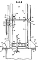
- Fig. 2 is a slightly enlarged side elevational view of the apparatus of Fig. 1, as viewed from the righthand side thereof, with the calibration tank in vertical section;
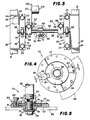
- Fig.- 3 is a fragmentary top plan view of the apparatus of Fig. 2, but on the same scale as Fig. 1;
- Fig. 4 is an enlarged top plan view of the transducer mounting assembly of the present invention; and
- Fig. 5 is a view in vertical section taken along the line 5-5 in Fig. 4.
- Referring to Figs. 1-3 of the drawings, there is illustrated a calibration apparatus, generally designated by the
numeral 10 for calibrating atransducer array 85. Thetransducer array 85 is calibrated by moving it across a calibration block 11 which has an arcuateupper surface 12 identical in curvature to a portion of a nuclear steam generating vessel to be inspected by the transducer array as part of an ultrasonic inspection process. The calibration block 11 is immersed in water in acalibration tank 13, and more particularly, is supported on thefloor 14 thereof. The water provides a transmission medium for the ultrasonic waves. The calibration block 11 may be supported in an underwaterload bearing device 15 which has aframe 16 carrying asupport box 17 in which the calibration block 11 is mounted. Thetank 13 is filled with water to alevel 19. The calibration block 11 has known defects so that the response of thetransducer array 85 thereto can form a basis for calibration. - The
calibration apparatus 10 includes asupport frame 20 which is mounted on top of thecalibration tank 13. Thesupport frame 20 includes a pair ofchannel beams 21 extending alongside thetank 13 and fixedly secured thereto adjacent to the upper end thereof. Mounted on thechannel beams 21 are tworectangular support plates 22, respectively disposed along opposite sides of thetank 13. Eachsupport plate 22 carries a pair ofsupport posts 23 which are fixedly secured to thesupport plate 22 and extend vertically upwardly therefrom. Fourgusset plates 24 are respectively associated with thesupport posts 23, eachgusset plate 24 interconnecting the associatedsupport post 23 and the adjacent end of the associatedsupport plate 22. Each of thesupport posts 23 of one pair thereof has formed on the outer surface thereof, facing outwardly toward one side of thetank 13, an elongatedlinear scale 25. Thesupport plate 22 carrying thosesupport posts 23 also has mounted thereon amounting bracket 26 on which is supported an associatedcontrol box 27 for controlling the operation of thecalibration apparatus 10. - The four
support posts 23 are identical in construction, each being in the form of a circular cylinder, theposts 23 being arranged in a rectangular configuration. Mounted on thesupport posts 23 is a pendulum carriage assembly, generally designated by thenumeral 30. More particularly, two horizontally extendingclamp bars 31 are provided, eachclamp bar 31 interconnecting an associated pair of thesupport posts 23. Eachclamp bar 31 has cylindricalvertical bores 32 therethrough adjacent to the opposite ends thereof for respectively receiving the associatedsupport posts 23, each end of theclamp bar 31 being formed with a pair of vertically-splitends 33 secured together by aclamp bolt 34 securely to clamp theclamp bar 31 to thesupport posts 23. Twopillow blocks 35 are respectively carried by theclamp bars 31 intermediate the ends thereof and projecting upwardly therefrom. Anelongated shaft 36 spans theclamp bars 31 substantially perpendicular thereto and has the opposite ends thereof respectively journaled in bearings of thepillow blocks 35. It will be appreciated that by loosening thebolts 34, the pendulum carriage assembly may be moved vertically along thesupport posts 23 to any desired position, the accurate location of such position being facilitated by thelinear scales 25. - Mounted on the
pendulum carriage assembly 30 is adrive assembly 40 which includes amounting bracket 41 carried by one of theclamp bars 31 and on which is mounted agearmotor 42 including a high ratio speed-reduction gear train. Thegearmotor 42 has anoutput shaft 43 to which is fixedly secured asprocket 44, which is in turn coupled by adrive chain 45 to asprocket 46 fixedly secured to theshaft 36. Thegearmotor 42 is reversible, and it will be appreciated that rotation of theoutput shaft 43 effects a corresponding rotation of theshaft 36. - Carried by the
shaft 36 is apendulum assembly 50 which includes a pair ofclamp blocks 51, respectively having bores therethrough for receiving theshaft 36, and provided with horizontallysplit ends 52 secured together byfasteners 53 securely to clamp theclamp blocks 51 to theshaft 36. Each of the clamp blocks 51 projects rearwardly from theshaft 36 and is provided adjacent to its rearward end with avertical bore 55 for receiving a corresponding one of two elongatedcylindrical pendulum arms 56. Each of theclamp blocks 51 has vertically splitrear ends 54 which are secured together byfasteners 57 securely to clamp theclamp blocks 51 to thependulum arms 56. Each of thependulum arms 56 has a length approximately the same as that of thesupport posts 23 and extends substantially parallel thereto. - Each of the
pendulum arms 56 has fixedly secured thereto at the lower end thereof a pair ofmounting blocks 58 spaced apart longitudinally of thependulum arms 56. Each of themounting blocks 58 has a vertical bore therethrough for receiving the lower end of the associatedpendulum arm 56, being fixedly secured thereto by a suitable set screw. Eachmounting block 58 also has a horizontal bore extending therethrough forwardly of thependulum arms 56 for receiving the associated end of one of a pair of vertically spaced-aparthorizontal cross bars 59, being fixedly secured thereto by suitable set screws. Thus, it will be appreciated that theshaft 36, thependulum arms 56 and thecross bars 59 cooperate to provide a rigid rectangular pendulum assembly which swings with the rotation of theshaft 36 and is extremely stable and accurate, having negligible sway or wobble. - Mounted on the
cross bars 59 is atransducer carriage block 60 which has two horizontal bores therethrough for respectively receiving thecross bars 59 and accommodating sliding movement longitudinally thereof. Aset screw 61 is provided for fixing thetransducer carriage block 60 to thelower cross bar 59 at any predetermined position therealong. Thetransducer carriage block 60 also has a vertical bore therethrough slidably receiving therein anelongated support shaft 62 which is provided with aneye bolt 63 in the upper end thereof and is externally threaded at its lower end, as at 64. Another set screw 61a holds theshaft 62 in any desired vertical position. Alinear scale 65 is provided on the front surface on the upper one of the cross bars 59, while alinear scale 66 is provided on one side of thevertical shaft 62 for facilitating accurate positioning of thesupport block 60 along the cross bars 59 and positioning of theshaft 62 with respect to thecarriage block 60. - Referring now also to Figs. 4 and 5, a
transducer mounting assembly 70 is carried by thesupport shaft 62 at its lower end. More specifically, thetransducer mounting assembly 70 includes acylindrical sleeve 71 threadedly engaged with the lower end of theshaft 62 coaxially therewith and projecting therebelow. An annular dial support plate 72, having anannular dial disk 73 on the upper surface thereof, is fixedly secured to the bottom of thesleeve 71 by suitable fasteners, such as screws 74. Extending coaxially into the lower end of thesleeve 71, threadedly engaged therewith and extending therebelow is astud 76. Received over the lower end of thestud 76 is acylindrical bearing 75. Fitted telescopically over the bearing 75 is anannular housing plate 77 which extends laterally beyond the outer edges of the dial support plate 72.Washers 78 and anut 79 cooperate with thestud 76 fixedly to hold thebearing 75 and thehousing plate 77 in place. - A
lock block 80 overlies thehousing plate 77 and is secured thereto by aroll pin 81. Thelock block 80 has a disk-engaginglug 82 which extends radially inwardly and overlies the upper surface of thedial disk 73. A clampingscrew 83 extends through thelock block 80 and into thehousing plate 77 for adjusting the frictional force with which the disk-engaginglug 82 engages thedial disk 73. Thus, it will be appreciated that when thelock block 80 is tightened down in its locking configuration, illustrated in Fig. 5, thedial disk 73 and thehousing plate 77 are clamped together so that thehousing plate 77 is not movable with respect to the dial support plate 72. Thescrew 83 is loosened to unlock thelock block 80 and permit thehousing plate 77 to be freely rotated about the axis of thestud 76 with respect to thedial disk 73. Mounted on the upper surface of thehousing plate 77 is anindex plate 84 which cooperates with a dial scale (not shown) on thedial disk 73 accurately to indicate the angular position of thehousing plate 77 with respect to thedial disk 73. - A
transducer array 85 to be calibrated is fixedly secured to thehousing plate 77. More specifically, thetransducer array 85 is provided with anannular base plate 86 which is fixedly secured to the underside of thehousing plate 77 by suitable fasteners 88 (see Fig. 4). Thebase plate 86 carries a plurality ofultrasonic transducers 87, including transmitting transducers and receiving transducers, which are oriented in a manner determined by the nature and shape of the particular calibration block 11 to be used in the calibration procedure. - Also mounted on the
pendulum carriage assembly 30 adjacent to thedrive assembly 40 is adial assembly 90. More specifically, twoelongated support brackets 91 are fixedly secured to the associatedclamp bar 31 and depend vertically therefrom. Aflat dial plate 92 is fixedly secured to thesupport brackets 91 outboard thereof byfasteners 93, thedial plate 92 having an arcuate lower edge provided with ascale 94. Anelongated pointer 95 has ahub 96 at one end thereof which is fixedly secured to the adjacent end of theshaft 36 for rotation therewith. Thus, it will be appreciated that thepointer 95 indicates on thescale 94 the angular position of thependulum assembly 50, thepointer 95 being vertical when thependulum assembly 50 is oriented vertically. Preferably thescale 94 of thedial assembly 90 is calibrated in radians so that the travel distance of thependulum assembly 50 along its travel arc may be determined by multiplying the angle in radians by the radius of the travel arc. - Fixedly secured to the
clamp block 51 adjacent to thedrive assembly 40 is an elongatedrectangular bias arm 100 which projects rearwardly of thecalibration apparatus 10. Fixedly secured to thebias arm 100 adjacent to its distal end, as by afastener 101, is abias weight 102. Thebias weight 102 serves normally to bias thependulum assembly 50 to a rest position, indicated in broken line in Fig. 1, wherein thepointer 95 is off thescale 94 which defines the limits of the normal range of operation of thependulum assembly 50 during the calibration procedure. - The purpose of this bias arrangement is to avoid backlash in the
drive assembly 40. More particularly, thegearmotor 42 has a worm gear drive with a high speed-reduction ratio, which is characterized by high friction. This is advantageous in that it serves to hold thependulum assembly 50 in position when power to themotor 42 is shut off. But in this type of drive, each direction change of thegearmotor 42 is attended by backlash in the gear train. This "play" in the gear train effects a jolt at each extremity of the pendulum swing, and introduces a spurious movement into thependulum assembly 50 which adversely affects the accuracy of the calibration procedure. Thebias weight 102, by establishing the normal rest position of thependulum assembly 50 outside the normal calibration range, insures that the frictional forces on the gear train will always be exerted in the same direction, thereby eliminating the backlash. - In operation, the
pendulum assembly 50 is raised to a position where the lower end of thesupport shaft 62 is well above thecalibration tank 13, and thetransducer array 85 is mounted in place on thetransducer mounting assembly 70. The calibration block 11 is positioned in thecalibration tank 13 immediately below thecalibration apparatus 10, with the curvature of the arcuateupper surface 12 being oriented in the direction of the swing of thependulum assembly 50. Thependulum carriage assembly 30 is positioned so that theshaft 36 is disposed coaxially with the axis of curvature of theupper surface 12 of the calibration block 11. Thependulum assembly 50 is then lowered until thetransducer array 85 is positioned the predetermined desired distance from theupper surface 12 of the calibration block 11. - It is a significant feature of the present invention that accurate positioning of the
transducer array 85 is facilitated by several different degrees of adjustment of thependulum assembly 50. Thus, the entirependulum carriage assembly 30 may be moved vertically along the support posts 23. Also, the vertical position of thependulum assembly 50 may be coarsely adjusted by movement of thependulum arms 56 vertically with respect to the clamp blocks 51. A finer vertical adjustment may be effected by vertical movement of thesupport shaft 62 with respect to thetransducer carriage block 60. Horizontal positioning of thetransducer array 85 is effected by sliding thetransducer carriage block 60 horizontally along the cross bars 59. - When the
transducer array 85 has been accurately positioned over the calibration block 11, thegearmotor 42 is energized to move the pendulum assembly into the calibration range and swing it back and forth. It will be appreciated that the effective radius of thependulum assembly 50 is adjusted so that the arc traversed by thetransducer array 85 is coaxial with the arcuateupper surface 12 of the calibration block 11, so that the predetermined'distance therebetween remains constant. - The calibration block 11 may have a substantial width transversely of the
calibration apparatus 10. In order to cover theentire surface 12, it will be necessary to move thetransducer array 85 thereacross in sequential parallel passes. Thus, thetransducer carriage block 60 may be moved a slight distance horizontally after each pass to place thetransducer array 85 in position for the next pass. It will also be appreciated that by rotation of thehousing plate 77 of thetransducer mounting assembly 70, the angular rotation of thetransducer array 85 may also be changed, as desired. - A significant advantage of the present invention is its great stability and accuracy which is afforded by the
dual pendulum arms 56 and the dual cross bars 59. This rigid rectangular construction, plus thebias weight 102 which eliminates backlash from thedrive assembly 40, serves to provide a smooth and accurately controlled movement of thependulum assembly 50 at a constant and predictable rate of travel. - From the foregoing, it can be seen that there has been provided an improved calibration apparatus for calibrating ultrasonic transducer arrays, the apparatus being characterized by a simple and economical construction which affords great stability and accuracy of movement of the pendulum assembly, multiple adjustments of the position of the transducer array, including coarse and fine adjustments of the pendulum radius, and scales to indicate all ranges of adjustment and movement.
Claims (11)
1. An adjustable radius calibration apparatus for calibrating an ultrasonic transducer array by moving it along a calibration test member which has an arcuate surface, said array in use being moved in an arcuate path facing and in proximity of an arcuate surface to monitor the arcuate surface, said apparatus comprising: a frame disposable adjacent to the test member, carriage means mounted on said frame and defining a pivot axis extending through the center of curvature of said arcuate surface of said test member, means for fixing the position of said carriage means in a desired position on said frame for choosing the position of said pivot axis with respect to the test member thereby to accommodate a plurality of test members with different radii of curvature, an elongated pendulum arm mounted on said carriage and depending therefrom for arcuate movement about. said pivot axis, drive means for causing arcuate movement of said pendulum arm, and attachment means for mounting the transducer array on a lower end of said pendulum arm, whereby pivoting of said pendulum arm assists movement of the transducer array along the arcuate test member at a fixed predetermined distance therefrom for calibration purposes.
2. The calibration apparatus of claim 1, wherein said frame includes a plurality of upstanding posts, said carriage means extending between said posts and being mounted for selective sliding vertical movement therealong.
3. The calibration apparatus of claim 2, wherein said frame includes four upstanding posts in a rectangular arrangement, said carriage means including a framework interconnecting said posts.
4. The calibration apparatus of claim 1, wherein said attachment means includes means enabling oscillatory movement of the transducer array about a predetermined axis.
5. The calibration apparatus of claim 4, wherein said attachment means includes first and second coaxial annular members adapted for rotation with respect to each other about said predetermined axis, means attaching one of said annular members to said pendulum arm, means attaching the transducer array to the other of said annular members, and lock means engageable with said annular members for preventing relative rotation thereof.
6. The calibration apparatus of claim 4, wherein said attachment means-includes a swivel joint.
7. The calibration apparatus of claim 1, further including indicator means coupled to said pendulum arm for indicating a direction and extent of the arcuate movement thereof.
8. The calibration apparatus of claim 1, wherein said pendulum arm has a longitudinal axis which does not intersect said pivot axis.
9. The calibration apparatus of claim 1, and further including means for changing the position of said pendulum arm with respect to said carriage.
10. The calibration apparatus of claim 1, wherein said drive means comprises a speed reduction gear motor.
11. The calibration apparatus of claim 10, further including bias means coupled to said pendulum arm for minimizing backlash in said speed reduction gear motor.
Applications Claiming Priority (2)
| Application Number | Priority Date | Filing Date | Title |
|---|---|---|---|
| US584226 | 1975-06-05 | ||
| US06/584,226 US4576034A (en) | 1984-02-27 | 1984-02-27 | Adjustable radius apparatus for calibrating ultrasonic transducer array |
Publications (1)
| Publication Number | Publication Date |
|---|---|
| EP0159484A1 true EP0159484A1 (en) | 1985-10-30 |
Family
ID=24336442
Family Applications (1)
| Application Number | Title | Priority Date | Filing Date |
|---|---|---|---|
| EP85101643A Withdrawn EP0159484A1 (en) | 1984-02-27 | 1985-02-15 | Adjustable radius apparatus for calibrating ultrasonic transducer array |
Country Status (7)
| Country | Link |
|---|---|
| US (1) | US4576034A (en) |
| EP (1) | EP0159484A1 (en) |
| JP (1) | JPS60203855A (en) |
| KR (1) | KR850007161A (en) |
| CA (1) | CA1230946A (en) |
| ES (1) | ES8701989A1 (en) |
| ZA (1) | ZA85912B (en) |
Cited By (8)
| Publication number | Priority date | Publication date | Assignee | Title |
|---|---|---|---|---|
| EP0239371A2 (en) * | 1986-03-26 | 1987-09-30 | Westinghouse Electric Corporation | Apparatus for ultrasonically inspecting a large shaft from a liquid-filled bore |
| EP0639770A1 (en) * | 1993-08-09 | 1995-02-22 | Westinghouse Electric Corporation | Calibration arrangement and method for calibrating an inspection instrument |
| WO2008041887A1 (en) * | 2006-10-03 | 2008-04-10 | Popovich Alexandr Maximilyanov | Method for tuning the measuring system of an inspection pig and a tuning device |
| CN105866256A (en) * | 2016-03-30 | 2016-08-17 | 西北工业大学 | Automatic ultrasonic transducer calibrating apparatus |
| US10012762B2 (en) | 2015-03-26 | 2018-07-03 | Halliburton Energy Services, Inc. | Standoff determination |
| US10386533B2 (en) | 2015-03-26 | 2019-08-20 | Halliburton Energy Services, Inc. | Downhole tool apparatus, system, and methods |
| US10393917B2 (en) | 2015-03-26 | 2019-08-27 | Halliburton Energy Services, Inc. | Cement evaluation with X-ray tomography |
| WO2019215207A1 (en) | 2018-05-10 | 2019-11-14 | Cis Pharma Ag | Biocompatible copolymer containing multiple active agent molecules |
Families Citing this family (16)
| Publication number | Priority date | Publication date | Assignee | Title |
|---|---|---|---|---|
| EP0229981B1 (en) * | 1985-12-20 | 1990-02-28 | Siemens Aktiengesellschaft | Method for controlling the focussing characteristics of an ultrasonic field and device for carrying out said method |
| US5010525A (en) * | 1990-01-02 | 1991-04-23 | Westinghouse Electric Corp. | Sonar test system and method |
| US5203199A (en) * | 1990-10-12 | 1993-04-20 | Teledyne Industries, Inc. | Controlled acceleration platform |
| US5420898A (en) * | 1992-03-17 | 1995-05-30 | Combustion Engineering, Inc. | Remote manipulator |
| US5419195A (en) * | 1993-04-30 | 1995-05-30 | Westinghouse Electric Corporation | Ultrasonic booted head probe for motor bore inspection |
| US5381383A (en) * | 1993-12-02 | 1995-01-10 | Unisys Corporation | Sonar transducer calibration apparatus and method |
| US5642331A (en) * | 1996-02-02 | 1997-06-24 | The United States Of America As Represented By The Secretary Of The Navy | Constant radius acoustic sensor mounting system |
| US20070107488A1 (en) * | 2005-10-26 | 2007-05-17 | Scott Farrell | System and method for enabling calibration of sensors used for detecting leaks in compartments |
| CN101711358B (en) * | 2007-05-15 | 2013-07-24 | 西门子公司 | Method and device for non-destructive material testing of a test object using ultrasonic waves |
| US7578166B2 (en) * | 2008-01-14 | 2009-08-25 | Grant Prideco, L.P. | Acoustic transducer calibration block and method |
| RU2530181C1 (en) * | 2013-05-15 | 2014-10-10 | Общество с ограниченной ответственностью "Научно-производственный центр неразрушающего контроля "ЭХО+" | Calibration method of ultrasonic antenna array installed on prism |
| US9377386B2 (en) * | 2013-08-23 | 2016-06-28 | Tinius Olsen Testing Machine Company | Impact tester having a safety return arm |
| FR3034545B1 (en) * | 2015-03-31 | 2018-05-11 | Vallourec Tubes France | TOOLS FOR CALIBRATING AN ULTRASONIC CONTROL DEVICE |
| CN111854589A (en) * | 2019-04-29 | 2020-10-30 | 核工业理化工程研究院 | Rapid calibration device and calibration method for contact type displacement sensor array |
| CN112986400B (en) * | 2019-12-13 | 2022-10-25 | 中车唐山机车车辆有限公司 | Probe moving auxiliary device |
| CN111412932B (en) * | 2020-04-30 | 2022-10-28 | 中国船舶重工集团公司第七0七研究所 | Special adjusting device and adjusting method suitable for multi-type buffer base |
Citations (3)
| Publication number | Priority date | Publication date | Assignee | Title |
|---|---|---|---|---|
| US3765229A (en) * | 1972-03-27 | 1973-10-16 | Nasa | Ultrasonic scanner for radial and flat panels |
| US4196630A (en) * | 1978-05-18 | 1980-04-08 | Rudolph Dale C | Overhead arm assembly |
| US4311052A (en) * | 1979-01-11 | 1982-01-19 | Automation Industries, Inc. | Ultrasonic control contour follower |
Family Cites Families (10)
| Publication number | Priority date | Publication date | Assignee | Title |
|---|---|---|---|---|
| US3248933A (en) * | 1963-05-16 | 1966-05-03 | Automation Ind Inc | Ultrasonic inspection transducer assembly |
| US3480002A (en) * | 1967-01-24 | 1969-11-25 | Magnaflux Corp | Medical ultrasonic scanning system |
| US3678736A (en) * | 1970-08-03 | 1972-07-25 | Gen Electric | Machine with improved operating head traversing workpieces with curved surfaces |
| AU490475B1 (en) * | 1974-02-21 | 1976-08-26 | Commonwealth Of Australia, The | Moving ultrasonic transducer array |
| US3894425A (en) * | 1974-02-27 | 1975-07-15 | Us Army | Two-coordinate locating device for a ultrasonic search probe |
| US3952581A (en) * | 1974-11-29 | 1976-04-27 | Alco Standard Corporation | Ultrasonic flaw detecting apparatus for turbine rotors |
| DE2547472A1 (en) * | 1975-10-23 | 1977-04-28 | Interatom | Internal inspection of reactor vessel - using vertically movable arm pivotal about horizontal axis to sweep inner surface |
| DE2557992C3 (en) * | 1975-12-22 | 1978-06-29 | Kraftwerk Union Ag, 4330 Muelheim | Test system carrier for testing the connection nozzle area in pressure vessels, especially reactor pressure vessels of nuclear power plants with ultrasound |
| JPS5542022A (en) * | 1978-09-21 | 1980-03-25 | Central Res Inst Of Electric Power Ind | Remote drive system for supersonic probe |
| DE2849763C2 (en) * | 1978-11-16 | 1984-11-15 | Kraftwerk Union AG, 4330 Mülheim | Device for testing pressure vessel walls provided with protrusions |
-
1984
- 1984-02-27 US US06/584,226 patent/US4576034A/en not_active Expired - Lifetime
-
1985
- 1985-02-06 ZA ZA85912A patent/ZA85912B/en unknown
- 1985-02-13 CA CA000474238A patent/CA1230946A/en not_active Expired
- 1985-02-15 EP EP85101643A patent/EP0159484A1/en not_active Withdrawn
- 1985-02-27 ES ES540754A patent/ES8701989A1/en not_active Expired
- 1985-02-27 JP JP60036729A patent/JPS60203855A/en active Granted
- 1985-02-27 KR KR1019850001250A patent/KR850007161A/en not_active Application Discontinuation
Patent Citations (3)
| Publication number | Priority date | Publication date | Assignee | Title |
|---|---|---|---|---|
| US3765229A (en) * | 1972-03-27 | 1973-10-16 | Nasa | Ultrasonic scanner for radial and flat panels |
| US4196630A (en) * | 1978-05-18 | 1980-04-08 | Rudolph Dale C | Overhead arm assembly |
| US4311052A (en) * | 1979-01-11 | 1982-01-19 | Automation Industries, Inc. | Ultrasonic control contour follower |
Cited By (10)
| Publication number | Priority date | Publication date | Assignee | Title |
|---|---|---|---|---|
| EP0239371A2 (en) * | 1986-03-26 | 1987-09-30 | Westinghouse Electric Corporation | Apparatus for ultrasonically inspecting a large shaft from a liquid-filled bore |
| EP0239371A3 (en) * | 1986-03-26 | 1990-02-07 | Westinghouse Electric Corporation | Apparatus for ultrasonically inspecting a large shaft from a liquid-filled bore |
| EP0639770A1 (en) * | 1993-08-09 | 1995-02-22 | Westinghouse Electric Corporation | Calibration arrangement and method for calibrating an inspection instrument |
| WO2008041887A1 (en) * | 2006-10-03 | 2008-04-10 | Popovich Alexandr Maximilyanov | Method for tuning the measuring system of an inspection pig and a tuning device |
| US10012762B2 (en) | 2015-03-26 | 2018-07-03 | Halliburton Energy Services, Inc. | Standoff determination |
| US10209398B2 (en) | 2015-03-26 | 2019-02-19 | Halliburton Energy Services, Inc. | Drilling fluid property determination |
| US10386533B2 (en) | 2015-03-26 | 2019-08-20 | Halliburton Energy Services, Inc. | Downhole tool apparatus, system, and methods |
| US10393917B2 (en) | 2015-03-26 | 2019-08-27 | Halliburton Energy Services, Inc. | Cement evaluation with X-ray tomography |
| CN105866256A (en) * | 2016-03-30 | 2016-08-17 | 西北工业大学 | Automatic ultrasonic transducer calibrating apparatus |
| WO2019215207A1 (en) | 2018-05-10 | 2019-11-14 | Cis Pharma Ag | Biocompatible copolymer containing multiple active agent molecules |
Also Published As
| Publication number | Publication date |
|---|---|
| US4576034A (en) | 1986-03-18 |
| JPH0238908B2 (en) | 1990-09-03 |
| KR850007161A (en) | 1985-10-30 |
| ES8701989A1 (en) | 1986-12-01 |
| CA1230946A (en) | 1987-12-29 |
| ZA85912B (en) | 1985-09-25 |
| ES540754A0 (en) | 1986-12-01 |
| JPS60203855A (en) | 1985-10-15 |
Similar Documents
| Publication | Publication Date | Title |
|---|---|---|
| US4576034A (en) | Adjustable radius apparatus for calibrating ultrasonic transducer array | |
| US4757716A (en) | Boresonic inspection system | |
| AU645640B2 (en) | Machining apparatus | |
| SE425189B (en) | SET AND DEVICE FOR OPERATING A COORDINATING MACHINE | |
| EP0251698A2 (en) | Boresonic inspection system | |
| JPS6126929Y2 (en) | ||
| US7242744B2 (en) | X-ray diffraction apparatus and method | |
| US4641532A (en) | Apparatus for adjustably mounting ultrasonic testing devices | |
| US4170891A (en) | Positioning calibration apparatus for transducers employed in nuclear reactor vessel inspection apparatus | |
| CN110470735B (en) | PAUT experimental apparatus of pipe fitting | |
| JPH02502848A (en) | Method and apparatus for testing elastic members having substantially linear spring deformability | |
| US4864862A (en) | Boresonic inspection system | |
| GB2238381A (en) | Detecting verticality and maintaining level | |
| US3952582A (en) | Ultrasonic inspection device and system | |
| EP1173751B1 (en) | X-ray diffraction apparatus and method | |
| CN114111974A (en) | Horizontal level gauge detects calibrating device | |
| US4277981A (en) | Lead screw actuated fluid gauge | |
| SE8800313D0 (en) | LOAD TRANSFER DEVICE FOR ELECTROMECHANICAL METHODS | |
| EP0131065A2 (en) | Method and apparatus for ultrasonic testing of tubular goods | |
| CN220169118U (en) | Transducer fixing device of single-beam depth finder | |
| CN114777737B (en) | Detection tool | |
| GB2237651A (en) | Calibration of vessel weighing systems | |
| SU1518658A1 (en) | Device for checking runouts of bearing rings | |
| JPH0622240Y2 (en) | Portable X-ray diffractometer | |
| RU1772635C (en) | Device for determining article center-of-mass coordinates |
Legal Events
| Date | Code | Title | Description |
|---|---|---|---|
| PUAI | Public reference made under article 153(3) epc to a published international application that has entered the european phase |
Free format text: ORIGINAL CODE: 0009012 |
|
| AK | Designated contracting states |
Designated state(s): BE CH DE FR GB IT LI SE |
|
| 17P | Request for examination filed |
Effective date: 19860313 |
|
| 17Q | First examination report despatched |
Effective date: 19871008 |
|
| STAA | Information on the status of an ep patent application or granted ep patent |
Free format text: STATUS: THE APPLICATION IS DEEMED TO BE WITHDRAWN |
|
| 18D | Application deemed to be withdrawn |
Effective date: 19890128 |
|
| RIN1 | Information on inventor provided before grant (corrected) |
Inventor name: VESTOVICH, ROBERT PAUL Inventor name: FERREE, HERBERT EDWARD Inventor name: KLINVEX, DANIEL EDWARD |