EP0156984A2 - Hair processing apparatus - Google Patents
Hair processing apparatus Download PDFInfo
- Publication number
- EP0156984A2 EP0156984A2 EP84115290A EP84115290A EP0156984A2 EP 0156984 A2 EP0156984 A2 EP 0156984A2 EP 84115290 A EP84115290 A EP 84115290A EP 84115290 A EP84115290 A EP 84115290A EP 0156984 A2 EP0156984 A2 EP 0156984A2
- Authority
- EP
- European Patent Office
- Prior art keywords
- framework
- hair
- promoting apparatus
- infrared radiating
- infrared
- Prior art date
- Legal status (The legal status is an assumption and is not a legal conclusion. Google has not performed a legal analysis and makes no representation as to the accuracy of the status listed.)
- Granted
Links
Images


Classifications
-
- A—HUMAN NECESSITIES
- A45—HAND OR TRAVELLING ARTICLES
- A45D—HAIRDRESSING OR SHAVING EQUIPMENT; EQUIPMENT FOR COSMETICS OR COSMETIC TREATMENTS, e.g. FOR MANICURING OR PEDICURING
- A45D20/00—Hair drying devices; Accessories therefor
- A45D20/04—Hot-air producers
- A45D20/08—Hot-air producers heated electrically
- A45D20/14—Portable drying stands
-
- A—HUMAN NECESSITIES
- A45—HAND OR TRAVELLING ARTICLES
- A45D—HAIRDRESSING OR SHAVING EQUIPMENT; EQUIPMENT FOR COSMETICS OR COSMETIC TREATMENTS, e.g. FOR MANICURING OR PEDICURING
- A45D20/00—Hair drying devices; Accessories therefor
- A45D20/22—Helmets with hot air supply or ventilating means, e.g. electrically heated air current
- A45D20/24—Shape or structure of the helmet body
- A45D2020/245—Shape or structure of the helmet body of open configuration, e.g. with several movable heat sources
Definitions
- This invention relates to hair heat processing apparatus; and more particularly to hair heat processing apparatus of the infrared ray type.
- Hair promoting apparatus otherwise sometimes referred to as hair heat processing apparatus, are utilized today to heat and dry a person's hair. Such heating and drying is usually required during or after the hair has been processed such as perming, or while it is being worked such as drying, or for drying after washing, or for similar treatments.
- Some hair promoting or heat processing apparatus utilize infrared rays for heating and drying the hair.
- Conventionally available infrared hair promoting devices often incorporate an infrared radiator in the form of an elongated pipe of silica glass that is energized to generate heat and radiates far infrared rays to heat and dry hair.
- These devices are often formed so that the heat radiating member (in the elongated pipe for radiating far infrared rays), and a reflecting mirror, of the apparatus for reflecting infrared rays radiated from the heat radiating member, are formed to have a circular configuration. By doing so the distance between same and the hair to be processed may be made uniform at the center i and opposite ends of the infrared ray radiator.
- This invention involves infrared radiating hair promoting apparatus, and contemplates; utilizing a number of radiating mits each of linear construction and configuration, and each contained in an independent case.
- the independent casses are of common structure and are connected to each other, by conduits thus greatly reducing manufacturing costs and the like.
- the invention accordingly, consists in the features of construction, combination of elements, and arrangement of parts which will be exemplified in the system, device and article of manufacture hereinafter described, and of which the scope of application is as elucidated supra and as will be indicated in the appended claims.
- numerous alternatives within the scope of the present invention besides those alternatives preferred embodiments or modes of practicing the invention mentioned, supra, and those to be elucidated, infra, will occur to those skilled in the art.
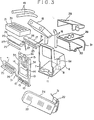
- FIGS 1 and 2 there is generally shown a hair promoting apparatus incorporating the instant invention and which includes a framework mounted in top of a main post 5 which is, in turn, mounted to and received by a main pipe 3.
- Pipe 3, and post 5 extend vertically up from the center of a base including a plurality of legs 2 each having a caster 1 mounted at an end thereof.
- An adjustment nut4, provided on top of pipe 3, when loosened permits post 6 to slide within pipe 3 and to be rotated therewithin to adjust the height of framework 6 and the positioning thereof.
- post 5 is prevented from movement within pipe 3.
- FIGS 1 and 2 show framework 6 disposed upon a movable base it should be understood tht framework 6 and, the apparatus associated therewith, may just as easily be securely suspended from a ceiling or securely mounted on a wall.
- Appropriate and conventional mounting structure would be utilized to so mount framework 6 in a thus relatively fixed position.
- conventional means would be provided for such a mounting to permit height and rotational adjustment of framework 6 and its associated apparatus.
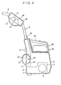
- Framework 6 has accommodated therein an air blower 7 (FIG. 3) a motor 8 for rotating blower 7, and a blast pipe 11 which is opened to louvers 10 (FIGS. 1 and 3) of a front cover 9 mounted on the front of framework 6.
- Front cover 9 (FIG. 2) has a window hole 13 (FIG. 3) perforated therein in which a radiator unit 12 (FIGS. 1 and 3) is accommodated such that the direction thereof can be adjusted upwardly and downwardly within an angle of about 10 degrees by operation of a semicircularly protruding knob 14.
- Front cover 9 further has a blasting louver 15 provided therein which allows an air flow to pass therethrough to cool radiator unit 12.
- a pair of pipes 16 extend erectly from the top of front cover 9.
- a head rear top case 18, in which a radiator unit 17 is accommodated is mounted at upper ends I of the pipes 16.
- Another pair of pipes 19 extend erectly from the head rear top case 18.
- a head front top case 21, in which a further radiator unit 20 is accommodated is mounted at upper ends of the pipes 19.
- a pair of connecting members 22 having a rectangular cross section are mounted on opposite left and right sides of framework 6.
- a side case 24 is mounted for rotation on an end of each of the connecting members 22 such that the direction of a further radiator 23 (FIG.11) mounted on each connecting member 22 and directed downwardly at an angle of 1 10 degrees, can be changed further downwardly by an angle of 20 degrees from this position.
- Each of the radiator units 12, 17, 20, and 23 includes a heat radiating member 25 (F I G. 3) having a linear silica glass pipe and a heating wire which is contained in the pipe and is energizable to generate heat in order that infrared rays or far infrared rays may be radiated from the silica glass pipe.
- a reflecting mirror 26, having a cross section approximated to a parabola for reflecting infrared rays or far infrared rays radiated from radiating members 25 is carried by units 12, 17,20 and 23.
- a wire gauze 27 (FIGS 3 and 4) for protecting heat radiating member 25 and reflecting mirror 26, and for preventing soiling of reflecting mirror 26 and possible burning of the skin of a person from an inadvertent touch with the heat radiating member 25, is appropriately positioned on units 12, 17, 20 and 23.
- a movable arm 35 (FIGS. 1 and 3), having a temperature sensor 34 (FIG. 3) mounted at one end thereof, is mounted at its other or a base end for pivotal motion on front cover 9.
- the mounting of arm 35 is such that it can be moved from a position adjacent front cover 9 to a position extending therefrom and in which temperature sensor 34 is located on an extension of a center line of front cover 9.
- a further indicator member 36 (FIGS. 1, 2, and 4) is provided at the top of front cover 9 and has a bulb contained therein which is energized simultaneously with energization of heat radiating members 25 to radiate light and indicate that heat radiating members 25 are now generating heat. i Consequently, the person can be prevented from touching and being burnt by, heat radiating members 25 without recognizing tht heat radiating members 25 are generating heat.
- Framework 6 has a hinge portion 6a (FIG. 3) protuding from one of the side faces thereof.
- a control unit 30 is mounted at a side portion thereof for pivotal motion on hinge portion 6a of the framework 6.
- Control unit 30 has a number of controlling switches 28 (FIGS. 2, 4, and 6) thereon and contains a control circuit 29 (FIG. 3) which is responsive to operation of switches 28 for controlling duration of electric current flowing through heat radiating members 25, and so on.
- control unit 30 ⁇ an be positioned to a position above an upper face of framework 6 to allow switches 28 threon to be operated from behind the hair promoting apparatus, of unit 30 can be pivoted sidewardly of framework 6 to allow switches 28 to be operated from the fornt side of the hair promoting apparatus. Accordingly, operations for controlling the hair promoting apparatus are possible from various positions around framework 6 depending upon the position of the hair promoting apparatus relative to a floor and a wall or walls.
- An electrical conducttor 31 extends from control circuit 29 through pipes 16 and 19 and connects radiation units 17 and 20 to control circuit 29. Conductor 31 also extends through connecting pipes 22 and connects radiator units 23 to control circuit 29. Accordingly, the electric conductor 31 cannot be observed from outside, thus preventing deterioration of the appearance of the hair promoting apparatus.
- the hair promoting apparatus which has such a construction as described above is actually used, it is moved in an arbitrary position by means of the casters 1 and legs 2.
- Nut 4 is loosened to adjust the hair promoting apparatus relative to the height of the head of a person whereafter it is tightened to fix the apparatus again the thus adjusted position.
- the head of the person is observed: from between framework 6 and head rear top case 18; between head rear top case 18 and head front top case 21; from between pipes 16 and pipes 19; and from above and below side cases 24.
- the persons head may then be set in position so that it may be illuminated unifrmly over the hair thereof by infrared rays from radiator units 12, 17, 20 and 23.
- the directions of radiator unit 12 and 17 for the head rear portion and radiator units 23 for the head side portions are adjusted upwardly or downwardly depending upon the length of the hair at such positions.
- switches 28, as shown in Fig. 6, are selectively operated depending upon the permanent set, drying of the hair washed, kind of a mode of dyeing of the hair, intensity of cold liquid used, conditions of the hair such as thickness, degree of damage, water absorbing power, and so on.
- Such operation of switches 28 can be recognized from lighting of indicating lamp 32 on the indicator panel.
- heat radiating members 25 are energized to radiate infrared rays which are directed towards the hair to heat and dry the hair.
- the duration of such energization of heat radiating members 25 in controlled in accordance with an established program which is determined in response to operations of switches 28.
- motor 8 is energized to operate air blower 7 so that blasts of air are blown out from louvers 10 against the hair to promote drying of the same.
- circuit 29 operates to interrupt the electric current to heat radiating members 25 thereby preventing damage to the hair due to overheating.
- a rise of temperature in the interior of framework 6, head rear top case 18, head front top case 21 and side cases 24 is inhibited due to the fact that air is circulated through blasting louvers 15 and 33 perforated in those components. Thus, they can be prevented from overheating.
- radiator units 12 and 23 may be directed downwardly; while on the contrary where the person has short hair, they may be directed upwardly so that infrared rays may be illuminated uniformly on the entire hair irrespective of the length of the hair.
- side cases 24 are each arranged such that radiator units 23 thereon are inclined to have the front end thereof located upwardly, the heat radiating members 25 thereof are positioned to extend along a border of the hair. Accordingly, infrared rays illuminated on a face of a person are reduced in quantity when compared with a hair promoting apparatus of the horizontally installed type, thereby reducing a disagreeable feeling of the person arising from the fact that the face is heated, the eyes become fatigued by infrared rays, and so on.
- a heat radiating member has a linear configuration
- a radiator unit which reflects infrared rays radiated from the heat radiating member also has a linear configuration. Accordingl when compared with a conventional hair promoting apparatus which includes a radiator unit having a circular configuration extending around a head of a person, according to the hair promoting apparatus, the distance from the head to the heat radiating member or to the radiator unit is seldom varied extremely even if the position of the head varies.
- radiator units provided for a head front top poriton and a head rear top poriton are contained in independent cases and connected to a framework by means of pipes, a sufficient spacing can be provided for the head of a person. Accordingly, removal of steam and circulation of air can be assured sufficiently promoting drying of a hair, and since the head can be thus observed well, the positioning of the head can be advantageously attained easily.
- the hair promoting apparatus is advantageous in that the electric wire is not exposed outside and hence the appearance of the apparatus is not iimpaired by the electric wire.
Landscapes
- Radiation-Therapy Devices (AREA)
- Cleaning And Drying Hair (AREA)
Abstract
Description
- This invention relates to hair heat processing apparatus; and more particularly to hair heat processing apparatus of the infrared ray type.
- Hair promoting apparatus, otherwise sometimes referred to as hair heat processing apparatus, are utilized today to heat and dry a person's hair. Such heating and drying is usually required during or after the hair has been processed such as perming, or while it is being worked such as drying, or for drying after washing, or for similar treatments.
- Some hair promoting or heat processing apparatus utilize infrared rays for heating and drying the hair. Conventionally available infrared hair promoting devices often incorporate an infrared radiator in the form of an elongated pipe of silica glass that is energized to generate heat and radiates far infrared rays to heat and dry hair. These devices are often formed so that the heat radiating member (in the elongated pipe for radiating far infrared rays), and a reflecting mirror, of the apparatus for reflecting infrared rays radiated from the heat radiating member, are formed to have a circular configuration. By doing so the distance between same and the hair to be processed may be made uniform at the center i and opposite ends of the infrared ray radiator.
- Utilizing such conventionally available hair promoting apparatus, however, requires that the person's head be accurately ¡positioned, and that it not be moved while the hair is being processed. Thus the person, who must keep their head so accurately positioned, may become fatigued and otherwise uncomfortable.
- It is therefore an object of this invention to provide a new and improved hair promoting apparatus.
- It is another object of this invention to provide a new and improved hair heat processing apparatus.
- It is yet another object of this invention to provide a new and improved infrared radiating hair promoting apparatus.
- It is still another object of this invention to provide a new and improved infrared radiating hair promoting apparatus which utilizes infrared radiating members which are of linear construction and configuration thus permitting some head movement while disposed there between.
- It is yet still another object of this invention to provid a new and improved infrared radiating hair promoting apparatus wherein a number of radiating units are each accomodated in independent cases of common structure and the units are, in turn, connected to each other by connecting conducts thus reducing the cost of dies, molds and the like.
- Other objects, features, and advantages of the invention in its details of construction and arrangement of parts will be seen from the above, from the following descriptions of the preferred embodiment when considered with the drawing and from the appended claims. In addition, these and other objects and advantages of the present invention will become evident from the description which follows.
- This invention involves infrared radiating hair promoting apparatus, and contemplates; utilizing a number of radiating mits each of linear construction and configuration, and each contained in an independent case. The independent casses are of common structure and are connected to each other, by conduits thus greatly reducing manufacturing costs and the like.
- The invention, accordingly, consists in the features of construction, combination of elements, and arrangement of parts which will be exemplified in the system, device and article of manufacture hereinafter described, and of which the scope of application is as elucidated supra and as will be indicated in the appended claims. In this regard, numerous alternatives within the scope of the present invention, besides those alternatives preferred embodiments or modes of practicing the invention mentioned, supra, and those to be elucidated, infra, will occur to those skilled in the art.
- In the drawings:
- FIG.1 is a perspective view, of an infrared hair promoting apparatus incorporating the instant invention, as viewed from the front of the apparatus.
- FIG.2 is a perspective view of the apparatus of FIG.l as viewed from the rear of the apparatus;
- FIG.3 is a perspective view of the apparatus of FIG's 1 and 2 but showing some in a disassembled condition;
- FlG.4 is a vertical sectional view of a portion of the apparatus of FIG. 1 and 2;
- FIG. 5 is a vertical sectional view of a radiator unit of the apparatus of FIGS. 1 and 2; and
- FIG. 6 is a plain view of an operation panel of the apparatus of FIGS. 1 and 2.
- With reference to FIGS 1 and 2 there is generally shown a hair promoting apparatus incorporating the instant invention and which includes a framework mounted in top of a
main post 5 which is, in turn, mounted to and received by amain pipe 3.Pipe 3, andpost 5, extend vertically up from the center of a base including a plurality oflegs 2 each having acaster 1 mounted at an end thereof. An adjustment nut4, provided on top ofpipe 3, when loosenedpermits post 6 to slide withinpipe 3 and to be rotated therewithin to adjust the height offramework 6 and the positioning thereof. Whennut 4 is tightenedpost 5 is prevented from movement withinpipe 3. - While FIGS 1 and 2
show framework 6 disposed upon a movable base it should be understood thtframework 6 and, the apparatus associated therewith, may just as easily be securely suspended from a ceiling or securely mounted on a wall. Appropriate and conventional mounting structure would be utilized to so mountframework 6 in a thus relatively fixed position. Obviously conventional means would be provided for such a mounting to permit height and rotational adjustment offramework 6 and its associated apparatus. - Framework 6 has accommodated therein an air blower 7 (FIG. 3) a
motor 8 for rotatingblower 7, and a blast pipe 11 which is opened to louvers 10 (FIGS. 1 and 3) of afront cover 9 mounted on the front offramework 6. - Front cover 9 (FIG. 2) has a window hole 13 (FIG. 3) perforated therein in which a radiator unit 12 (FIGS. 1 and 3) is accommodated such that the direction thereof can be adjusted upwardly and downwardly within an angle of about 10 degrees by operation of a semicircularly protruding
knob 14.Front cover 9 further has ablasting louver 15 provided therein which allows an air flow to pass therethrough tocool radiator unit 12. - A pair of pipes 16 (FIGS. 1-3) extend erectly from the top of
front cover 9. A headrear top case 18, in which aradiator unit 17 is accommodated is mounted at upper ends I of thepipes 16. Another pair ofpipes 19 extend erectly from the headrear top case 18. A headfront top case 21, in which afurther radiator unit 20 is accommodated is mounted at upper ends of thepipes 19. Thus, infrared rays may be radiated to a front top portion and a rear top portion of a person's head fromradiator units - A pair of connecting
members 22 having a rectangular cross section are mounted on opposite left and right sides offramework 6. Aside case 24 is mounted for rotation on an end of each of the connectingmembers 22 such that the direction of a further radiator 23 (FIG.11) mounted on each connectingmember 22 and directed downwardly at an angle of 110 degrees, can be changed further downwardly by an angle of 20 degrees from this position. - Each of the
radiator units mirror 26, having a cross section approximated to a parabola for reflecting infrared rays or far infrared rays radiated from radiatingmembers 25 is carried byunits - A wire gauze 27 (FIGS 3 and 4) for protecting
heat radiating member 25 and reflectingmirror 26, and for preventing soiling of reflectingmirror 26 and possible burning of the skin of a person from an inadvertent touch with theheat radiating member 25, is appropriately positioned onunits - A movable arm 35 (FIGS. 1 and 3), having a temperature sensor 34 (FIG. 3) mounted at one end thereof, is mounted at its other or a base end for pivotal motion on
front cover 9. The mounting ofarm 35 is such that it can be moved from a positionadjacent front cover 9 to a position extending therefrom and in whichtemperature sensor 34 is located on an extension of a center line offront cover 9. - Thus, if
movable arm 35 is moved as described just above to bringtemperature sensor 34 to a position near a rear portion of a head of a person, then allradiator units - A further indicator member 36 (FIGS. 1, 2, and 4) is provided at the top of
front cover 9 and has a bulb contained therein which is energized simultaneously with energization ofheat radiating members 25 to radiate light and indicate thatheat radiating members 25 are now generating heat. i Consequently, the person can be prevented from touching and being burnt by,heat radiating members 25 without recognizing ththeat radiating members 25 are generating heat. -
Framework 6 has a hinge portion 6a (FIG. 3) protuding from one of the side faces thereof. Acontrol unit 30 is mounted at a side portion thereof for pivotal motion on hinge portion 6a of theframework 6.Control unit 30 has a number of controlling switches 28 (FIGS. 2, 4, and 6) thereon and contains a control circuit 29 (FIG. 3) which is responsive to operation ofswitches 28 for controlling duration of electric current flowing throughheat radiating members 25, and so on. - Thus,
control unit 30 ^an be positioned to a position above an upper face offramework 6 to allowswitches 28 threon to be operated from behind the hair promoting apparatus, ofunit 30 can be pivoted sidewardly offramework 6 to allowswitches 28 to be operated from the fornt side of the hair promoting apparatus. Accordingly, operations for controlling the hair promoting apparatus are possible from various positions aroundframework 6 depending upon the position of the hair promoting apparatus relative to a floor and a wall or walls. - An
electrical condustor 31 extends fromcontrol circuit 29 throughpipes radiation units control circuit 29.Conductor 31 also extends through connectingpipes 22 and connectsradiator units 23 to controlcircuit 29. Accordingly, theelectric conductor 31 cannot be observed from outside, thus preventing deterioration of the appearance of the hair promoting apparatus. - Thus, when the hair promoting apparatus which has such a construction as described above is actually used, it is moved in an arbitrary position by means of the
casters 1 andlegs 2.Nut 4 is loosened to adjust the hair promoting apparatus relative to the height of the head of a person whereafter it is tightened to fix the apparatus again the thus adjusted position. - Then, the head of the person is observed: from between
framework 6 and head reartop case 18; between head reartop case 18 and head fronttop case 21; from betweenpipes 16 andpipes 19; and from above and belowside cases 24. The persons head may then be set in position so that it may be illuminated unifrmly over the hair thereof by infrared rays fromradiator units radiator unit radiator units 23 for the head side portions are adjusted upwardly or downwardly depending upon the length of the hair at such positions. - Subsequently, switches 28, as shown in Fig. 6, are selectively operated depending upon the permanent set, drying of the hair washed, kind of a mode of dyeing of the hair, intensity of cold liquid used, conditions of the hair such as thickness, degree of damage, water absorbing power, and so on. Such operation of
switches 28 can be recognized from lighting of indicatinglamp 32 on the indicator panel. - In response to such selective operations of
switches 28,heat radiating members 25 are energized to radiate infrared rays which are directed towards the hair to heat and dry the hair. The duration of such energization ofheat radiating members 25 in controlled in accordance with an established program which is determined in response to operations ofswitches 28. At the same time,motor 8 is energized to operateair blower 7 so that blasts of air are blown out fromlouvers 10 against the hair to promote drying of the same. - The temperature of the hair is detected by
temperature sensor 34, positioned adjacent the hear rear portion, and if it rises above a predetermined level, thencircuit 29 operates to interrupt the electric current to heat radiatingmembers 25 thereby preventing damage to the hair due to overheating. - Heated air caused by radiation of infrared rays from
heat radiating members 25, and also by drafting of air as described above, is escaped upwardly from betweenpipes - A rise of temperature in the interior of
framework 6, head reartop case 18, head fronttop case 21 andside cases 24 is inhibited due to the fact that air is circulated through blastinglouvers - Further, since blasted air through
louver 10 is directed to near the ears of a person, the ears which are heated by infrared rays are cooled by the air where the person has a hair style in which the ears are exposed outside, thus moderating a possible disagreeable feeding of the person. Besides, where the person has long hair,radiator units - In addition, since
side cases 24 are each arranged such thatradiator units 23 thereon are inclined to have the front end thereof located upwardly, theheat radiating members 25 thereof are positioned to extend along a border of the hair. Accordingly, infrared rays illuminated on a face of a person are reduced in quantity when compared with a hair promoting apparatus of the horizontally installed type, thereby reducing a disagreeable feeling of the person arising from the fact that the face is heated, the eyes become fatigued by infrared rays, and so on. - As apparent from the foregoing description, according to a hair promoting apparatus of the present invention, a heat radiating member has a linear configuration, and a radiator unit which reflects infrared rays radiated from the heat radiating member also has a linear configuration. Accordingl when compared with a conventional hair promoting apparatus which includes a radiator unit having a circular configuration extending around a head of a person, according to the hair promoting apparatus, the distance from the head to the heat radiating member or to the radiator unit is seldom varied extremely even if the position of the head varies.
- Accordingly, there is no obstacle even if the head is moved to some extent during processing, and hence fatigue of I a person who undergoes processing can be reduced and the degree of freedom of reading and the like can be increased.
- Further, since radiator units provided for a head front top poriton and a head rear top poriton are contained in independent cases and connected to a framework by means of pipes, a sufficient spacing can be provided for the head of a person. Accordingly, removal of steam and circulation of air can be assured sufficiently promoting drying of a hair, and since the head can be thus observed well, the positioning of the head can be advantageously attained easily.
- Moreover, since a common component can be used for a head front top case and a head rear top case and such components are connected to each other by means of pipes, dies can be made small and hence an investment for such dies can be reduced, thus resulting in effective reduction of the cost for the entire apparatus.
- In addition, since an electric wire formed control unit is passed through those pipes, the hair promoting apparatus is advantageous in that the electric wire is not exposed outside and hence the appearance of the apparatus is not iimpaired by the electric wire.
- As various possible embodiments might be made of the invention, and as various changes might be made in th embodiments above set forth, it is to be understood that all matter herein described and shown in the accompanying drawings is to be interpreted as illustrative and not in a limiting sense. Thus, it will be understood by thoe skilled in the art that although preferred and alternative embodiments have been shown and described in accordance with the Patent Statutes, the invention is not limited thereto or thereby, since the embodiments of the invention particularly disclosed and described herein above are peresented merely as an example of the invention. Other embodiments, forms, and modifications of the invention, coming within the proper scope and spirit of the appended claims, will of course readily suggest themselves to those skilled in the art. Thus, while there has been described what is at presetn considered to be the preferred embodiments of the invention, it will be obvious to those skilled in the art that various chnages and modifications may be made therein, without departing from the invention, and it is, therefore, aimed in the appended claims to cover all such changes and modifications as fall within the true spirit and scope of the invention, and it is understood that, although I have shown the preferred from of my invention, vaious modifications may be made in the details thereof, I without departing from the spirit as comprehended by the following claims.
Claims (10)
Priority Applications (1)
| Application Number | Priority Date | Filing Date | Title |
|---|---|---|---|
| AT84115290T ATE52171T1 (en) | 1983-12-16 | 1984-12-12 | HAIR TREATMENT DEVICE. |
Applications Claiming Priority (4)
| Application Number | Priority Date | Filing Date | Title |
|---|---|---|---|
| JP192857/83U | 1983-12-16 | ||
| JP19285783U JPS60101003U (en) | 1983-12-16 | 1983-12-16 | hair promotion device |
| US63108484A | 1984-07-16 | 1984-07-16 | |
| US631084 | 1996-04-12 |
Publications (3)
| Publication Number | Publication Date |
|---|---|
| EP0156984A2 true EP0156984A2 (en) | 1985-10-09 |
| EP0156984A3 EP0156984A3 (en) | 1986-08-27 |
| EP0156984B1 EP0156984B1 (en) | 1990-04-25 |
Family
ID=26507559
Family Applications (1)
| Application Number | Title | Priority Date | Filing Date |
|---|---|---|---|
| EP84115290A Expired EP0156984B1 (en) | 1983-12-16 | 1984-12-12 | Hair processing apparatus |
Country Status (3)
| Country | Link |
|---|---|
| US (1) | US4914273A (en) |
| EP (1) | EP0156984B1 (en) |
| DE (1) | DE3482024D1 (en) |
Cited By (5)
| Publication number | Priority date | Publication date | Assignee | Title |
|---|---|---|---|---|
| EP0317902A3 (en) * | 1987-11-24 | 1990-06-13 | Takara Belmont Kabushiki Kaisha | Hair promoting apparatus |
| FR2644045A1 (en) * | 1989-03-09 | 1990-09-14 | Fre Gis Srl | Automatic appliance for drying the hair |
| EP0372443A3 (en) * | 1988-12-06 | 1992-01-22 | OLYMP KARL HERZOG GmbH & Co. | Hair-drying hood |
| FR2689735A1 (en) * | 1992-04-13 | 1993-10-15 | Krups Robert Gmbh Co Kg | Apparatus for blowing hot air to dry the hair. |
| WO2006091458A1 (en) | 2005-02-23 | 2006-08-31 | The Procter & Gamble Company | Device for the treatment of head hair by means of heat |
Families Citing this family (38)
| Publication number | Priority date | Publication date | Assignee | Title |
|---|---|---|---|---|
| USD707395S1 (en) * | 1920-01-31 | 2014-06-17 | Dyson Technology Limited | Part of a hand dryer |
| USD321411S (en) | 1989-09-06 | 1991-11-05 | Olymp Karl Herzog Gmbh & Co. | Hair dryer |
| US5050232A (en) * | 1990-03-28 | 1991-09-17 | Bgk Finishing Systems, Inc. | Movable heat treating apparatus utilizing proportionally controlled infrared lamps |
| US5279048A (en) * | 1991-08-23 | 1994-01-18 | Intelligent Designs, Inc. | Hands free hair dryer and hair dryer accessory |
| DE69527671T9 (en) * | 1994-04-27 | 2004-09-09 | Koninklijke Philips Electronics N.V. | Controlled air flow hair dryer |
| US6116250A (en) * | 1996-07-20 | 2000-09-12 | Wella Aktiengesellschaft | Process of permanent hair shaping |
| US6038786A (en) * | 1998-04-16 | 2000-03-21 | Excel Dryer Inc. | Hand dryer |
| KR200195568Y1 (en) * | 1998-06-26 | 2000-09-01 | 김대성 | Hair dryer |
| USD477111S1 (en) | 1999-08-07 | 2003-07-08 | Wella Ag | Hair dryer |
| US7039301B1 (en) | 1999-10-04 | 2006-05-02 | Excel Dryer, Inc. | Method and apparatus for hand drying |
| AU4052601A (en) * | 2000-01-22 | 2001-07-31 | Wella Aktiengesellschaft | Electric hair treatment appliance |
| KR100783442B1 (en) * | 2000-09-08 | 2007-12-07 | 다카라 벨몬트 가부시키가이샤 | Hair Treatment Promoter |
| JP4456254B2 (en) * | 2000-10-20 | 2010-04-28 | 株式会社大廣製作所 | Hair treatment promotion machine |
| JP4435398B2 (en) * | 2000-10-25 | 2010-03-17 | 株式会社大廣製作所 | Hair treatment promotion machine |
| JP4295440B2 (en) * | 2001-01-09 | 2009-07-15 | 株式会社三龍社 | Hair heating machine with concentric reverse rotation reducer |
| KR20030083461A (en) * | 2002-04-23 | 2003-10-30 | 송웅부 | hair dryer |
| USD527490S1 (en) * | 2003-04-11 | 2006-08-29 | Wella Aktiengesellschaft | Hair dryer |
| WO2006090306A1 (en) | 2005-02-28 | 2006-08-31 | The Procter & Gamble Company | Device for heat treatment |
| WO2007020649A2 (en) * | 2005-08-17 | 2007-02-22 | Y.K. Holdings Ltd. | Lice extermination system and method |
| GB2444028A (en) * | 2006-11-23 | 2008-05-28 | Stephen Ball | Personal drying apparatus with heater, fan and infra-red source |
| USD622445S1 (en) | 2006-12-05 | 2010-08-24 | Wella Aktiengesellschaft | Hair drying hood |
| EP2114133A4 (en) * | 2007-02-16 | 2011-11-09 | Y K Holdings Ltd | Lice extermination system and method |
| US8434238B2 (en) * | 2007-06-29 | 2013-05-07 | Andis Company | Hair dryer with light source |
| USD601750S1 (en) | 2007-10-19 | 2009-10-06 | Wella Aktiengesellschaft | Hair dryer |
| USD600856S1 (en) | 2007-10-24 | 2009-09-22 | American Dryer, Inc. | Hand dryer |
| USD628343S1 (en) | 2008-04-17 | 2010-11-30 | Wella Aktiengesellschaft | Infrared radiation dryer |
| US8693855B2 (en) * | 2009-05-07 | 2014-04-08 | Cambridge Engineering, Inc | Infra-red heater assembly |
| ES2795355T3 (en) * | 2009-07-10 | 2020-11-23 | Braun Gmbh | Automated hair care process |
| USD669222S1 (en) * | 2011-05-23 | 2012-10-16 | Dyson Limited | Part of a hand dryer |
| USD682472S1 (en) * | 2011-05-23 | 2013-05-14 | Dyson Technology Limited | Part of a hand dryer |
| USD678613S1 (en) * | 2011-12-12 | 2013-03-19 | Dyson Technology Limited | Part of a hand dryer |
| USD679055S1 (en) * | 2011-12-12 | 2013-03-26 | Dyson Technology Limited | Part of a hand dryer |
| USD676604S1 (en) * | 2012-08-09 | 2013-02-19 | Hokwang Industries Co., Ltd. | Cover of hand dryer |
| AU350542S (en) * | 2013-02-01 | 2013-09-02 | Dyson Technology Ltd | Part of a hand dryer |
| CN103799667A (en) * | 2014-02-21 | 2014-05-21 | 苏州智信通电子科技有限公司 | Multifunctional curling iron |
| US10820677B2 (en) * | 2015-06-05 | 2020-11-03 | Sherron M Thomas | Cordless hair dryer with ionizing solution |
| AU2017213447A1 (en) * | 2016-08-11 | 2018-03-01 | Pacific Trends International Pty Ltd | Heater and a control system for a heater |
| USD843552S1 (en) * | 2017-05-02 | 2019-03-19 | P.S. Pibbs, Inc. | Four-headed heating lamp assembly with adjustable arms |
Family Cites Families (20)
| Publication number | Priority date | Publication date | Assignee | Title |
|---|---|---|---|---|
| US1787251A (en) * | 1928-10-03 | 1930-12-30 | Eastern Lab Inc | Hair drying and treating apparatus |
| FR898979A (en) * | 1943-06-23 | 1945-05-14 | New hair drying process and related apparatus | |
| FR995503A (en) * | 1945-03-14 | 1951-12-04 | Improvements to devices for drying hair | |
| US2500872A (en) * | 1946-04-10 | 1950-03-14 | Root Frank Keniston | Paint baking apparatus |
| GB611663A (en) * | 1946-05-03 | 1948-11-02 | Patrick Francis Aloysius Grein | Improvements in and connected with hair waving |
| FR932187A (en) * | 1946-08-12 | 1948-03-15 | Hair dryer | |
| FR944623A (en) * | 1947-04-02 | 1949-04-11 | Advanced model of infrared hair dryer | |
| GB773514A (en) * | 1954-10-20 | 1957-04-24 | Raymond Bessone | Hair heater for permanent waving processes |
| FR1158364A (en) * | 1956-10-12 | 1958-06-13 | Combined electric heating and lighting device | |
| FR1261383A (en) * | 1960-04-07 | 1961-05-19 | Heated helmet for hair care | |
| US3867948A (en) * | 1971-05-03 | 1975-02-25 | Adolf Kallenborn | Infra red radiation means with fan means |
| FR2314638A7 (en) * | 1975-06-10 | 1977-01-07 | Velecta | Hair drier comprising two or three small driers - with each mounted on support and independently adjustable |
| CH604606A5 (en) * | 1975-12-03 | 1978-09-15 | Herbert Kubat | Adjustable infrared lamp for hair treatment |
| JPS5827921B2 (en) * | 1976-12-27 | 1983-06-13 | シャープ株式会社 | Heated permanent device |
| JPS5920161Y2 (en) * | 1977-04-30 | 1984-06-12 | シャープ株式会社 | Temperature sensor for heating permanent equipment |
| JPS6031602Y2 (en) * | 1978-04-14 | 1985-09-21 | シャープ株式会社 | Heated permanent device |
| JPS54136963A (en) * | 1978-04-14 | 1979-10-24 | Sharp Corp | Hot permanent waver |
| US4242810A (en) * | 1979-05-24 | 1981-01-06 | Blanco David M | Hair styling apparatus |
| US4265029A (en) * | 1979-12-04 | 1981-05-05 | Jenkins Kenneth A | Motor vehicle dryer stand |
| DE3133851A1 (en) * | 1981-08-27 | 1983-03-24 | Wella Ag | HEAT TREATMENT FOR HEAD HAIR |
-
1984
- 1984-12-12 DE DE8484115290T patent/DE3482024D1/en not_active Expired - Lifetime
- 1984-12-12 EP EP84115290A patent/EP0156984B1/en not_active Expired
-
1987
- 1987-05-26 US US07/056,262 patent/US4914273A/en not_active Expired - Fee Related
Cited By (6)
| Publication number | Priority date | Publication date | Assignee | Title |
|---|---|---|---|---|
| EP0317902A3 (en) * | 1987-11-24 | 1990-06-13 | Takara Belmont Kabushiki Kaisha | Hair promoting apparatus |
| EP0372443A3 (en) * | 1988-12-06 | 1992-01-22 | OLYMP KARL HERZOG GmbH & Co. | Hair-drying hood |
| FR2644045A1 (en) * | 1989-03-09 | 1990-09-14 | Fre Gis Srl | Automatic appliance for drying the hair |
| FR2689735A1 (en) * | 1992-04-13 | 1993-10-15 | Krups Robert Gmbh Co Kg | Apparatus for blowing hot air to dry the hair. |
| EP0565933A1 (en) * | 1992-04-13 | 1993-10-20 | Robert Krups GmbH & Co. KG | Hairdryer with an IR radiator and a device indicating emission of the radiation |
| WO2006091458A1 (en) | 2005-02-23 | 2006-08-31 | The Procter & Gamble Company | Device for the treatment of head hair by means of heat |
Also Published As
| Publication number | Publication date |
|---|---|
| US4914273A (en) | 1990-04-03 |
| DE3482024D1 (en) | 1990-05-31 |
| EP0156984B1 (en) | 1990-04-25 |
| EP0156984A3 (en) | 1986-08-27 |
Similar Documents
| Publication | Publication Date | Title |
|---|---|---|
| EP0156984A2 (en) | Hair processing apparatus | |
| EP0317902B1 (en) | Hair promoting apparatus | |
| US5268988A (en) | Electric hair treatment apparatus having heated air delivery arm rotatable in conical path about the hair being treated | |
| JP7270949B2 (en) | hair treatment equipment | |
| US2808124A (en) | Apparatus for supplying decontaminated air | |
| US2422450A (en) | Combined space heater and grill | |
| US6108934A (en) | Tanning hair drier and hair steamer and process of using | |
| JPH05321883A (en) | Electric fan | |
| JP3554618B2 (en) | Heating and drying equipment | |
| JPH0233684Y2 (en) | ||
| JPS6060453A (en) | Hot air generator | |
| JPS6347788Y2 (en) | ||
| JPH0563404U (en) | Rotary hair dryer | |
| SU1650137A1 (en) | Travelling steam bath | |
| JPH0233683Y2 (en) | ||
| JPH064545U (en) | Electric heating system | |
| JPS6096204A (en) | Hair promoting device | |
| JPS6130122Y2 (en) | ||
| EP0935100A2 (en) | Device for increasing the heating effect of a radiator of a building hot-water heating installation | |
| JP3820077B2 (en) | Bathroom clothes drying and heating ventilator | |
| JP2002333153A (en) | Dry heating equipment for bathroom | |
| JP2929851B2 (en) | heater | |
| JPH05203263A (en) | Radiation type heating machine | |
| JP4561923B2 (en) | Drying and heating equipment for bathroom | |
| JPS6133446Y2 (en) |
Legal Events
| Date | Code | Title | Description |
|---|---|---|---|
| PUAI | Public reference made under article 153(3) epc to a published international application that has entered the european phase |
Free format text: ORIGINAL CODE: 0009012 |
|
| AK | Designated contracting states |
Kind code of ref document: A2 Designated state(s): AT BE CH DE FR GB IT LI LU NL SE |
|
| PUAL | Search report despatched |
Free format text: ORIGINAL CODE: 0009013 |
|
| AK | Designated contracting states |
Kind code of ref document: A3 Designated state(s): AT BE CH DE FR GB IT LI LU NL SE |
|
| 17P | Request for examination filed |
Effective date: 19870226 |
|
| 17Q | First examination report despatched |
Effective date: 19870715 |
|
| GRAA | (expected) grant |
Free format text: ORIGINAL CODE: 0009210 |
|
| RAP3 | Party data changed (applicant data changed or rights of an application transferred) |
Owner name: TAKARA COMPANY, INC. |
|
| AK | Designated contracting states |
Kind code of ref document: B1 Designated state(s): AT BE CH DE FR GB IT LI LU NL SE |
|
| PG25 | Lapsed in a contracting state [announced via postgrant information from national office to epo] |
Ref country code: SE Effective date: 19900425 Ref country code: NL Effective date: 19900425 Ref country code: IT Free format text: LAPSE BECAUSE OF FAILURE TO SUBMIT A TRANSLATION OF THE DESCRIPTION OR TO PAY THE FEE WITHIN THE PRESCRIBED TIME-LIMIT;WARNING: LAPSES OF ITALIAN PATENTS WITH EFFECTIVE DATE BEFORE 2007 MAY HAVE OCCURRED AT ANY TIME BEFORE 2007. THE CORRECT EFFECTIVE DATE MAY BE DIFFERENT FROM THE ONE RECORDED. Effective date: 19900425 Ref country code: FR Effective date: 19900425 Ref country code: BE Effective date: 19900425 Ref country code: AT Effective date: 19900425 |
|
| REF | Corresponds to: |
Ref document number: 52171 Country of ref document: AT Date of ref document: 19900515 Kind code of ref document: T |
|
| REF | Corresponds to: |
Ref document number: 3482024 Country of ref document: DE Date of ref document: 19900531 |
|
| EN | Fr: translation not filed | ||
| NLV1 | Nl: lapsed or annulled due to failure to fulfill the requirements of art. 29p and 29m of the patents act | ||
| PG25 | Lapsed in a contracting state [announced via postgrant information from national office to epo] |
Ref country code: GB Effective date: 19901212 |
|
| PG25 | Lapsed in a contracting state [announced via postgrant information from national office to epo] |
Ref country code: LU Free format text: LAPSE BECAUSE OF NON-PAYMENT OF DUE FEES Effective date: 19901231 Ref country code: LI Free format text: LAPSE BECAUSE OF NON-PAYMENT OF DUE FEES Effective date: 19901231 Ref country code: CH Free format text: LAPSE BECAUSE OF NON-PAYMENT OF DUE FEES Effective date: 19901231 |
|
| PLBI | Opposition filed |
Free format text: ORIGINAL CODE: 0009260 |
|
| 26 | Opposition filed |
Opponent name: WELLA AG Effective date: 19901218 |
|
| GBPC | Gb: european patent ceased through non-payment of renewal fee | ||
| REG | Reference to a national code |
Ref country code: CH Ref legal event code: PL |
|
| PG25 | Lapsed in a contracting state [announced via postgrant information from national office to epo] |
Ref country code: DE Effective date: 19910903 |
|
| RDAG | Patent revoked |
Free format text: ORIGINAL CODE: 0009271 |
|
| STAA | Information on the status of an ep patent application or granted ep patent |
Free format text: STATUS: PATENT REVOKED |
|
| 27W | Patent revoked |
Effective date: 19911114 |