JP3554618B2 - Heating and drying equipment - Google Patents
Heating and drying equipment Download PDFInfo
- Publication number
- JP3554618B2 JP3554618B2 JP25393195A JP25393195A JP3554618B2 JP 3554618 B2 JP3554618 B2 JP 3554618B2 JP 25393195 A JP25393195 A JP 25393195A JP 25393195 A JP25393195 A JP 25393195A JP 3554618 B2 JP3554618 B2 JP 3554618B2
- Authority
- JP
- Japan
- Prior art keywords
- heating
- bathroom
- housing
- air
- far
- Prior art date
- Legal status (The legal status is an assumption and is not a legal conclusion. Google has not performed a legal analysis and makes no representation as to the accuracy of the status listed.)
- Expired - Fee Related
Links
Images


Description
【0001】
【発明の属する技術分野】
本発明は、浴室等の暖房機能と衣類の乾燥機能を備えた暖房乾燥装置に関するものである。
【0002】
【従来の技術】
従来、この種の暖房乾燥装置として、浴室の天井等に設置した暖房乾燥装置が知られている。
【0003】
この暖房乾燥装置は、ヒータと送風機とを搭載したもので、送風機により浴室内の空気を装置本体内に吸い込み、この吸い込まれた空気をヒータにより加熱して浴室内に循環するようになっている。この循環する加熱空気により浴室内を暖房する。
【0004】
他方、浴室を乾燥するときは、このヒータ及び送風機に加えて換気扇を稼働し、浴室内の加温と同時に湿気を屋外に排出し、衣類乾燥を行っている。
【0005】
【発明が解決しようとする課題】
しかしながら、前記従来の暖房乾燥装置では、天井から加温空気を循環し浴室を暖房しているため、温度の高い循環空気が浴室の天井側に滞留し易く、このため、天井側の温度が高い割には、浴室の床側の温度が低く、快適な浴室暖房とはいえなかった。
【0006】
また、浴室乾燥においても、換気扇で屋外に排出される空気が、同じく浴室の天井側に滞留した高温度が大部分であり、このため、乾燥温度が低く、衣類等の乾燥時間が長くなるという問題点を有していた。
【0007】
更に、この暖房乾燥装置は浴室専用で、加温空気を浴室に隣接する脱衣室等に循環できないため、汎用性に欠けるという問題点を有していた。
【0008】
本発明の目的は前記従来の課題に鑑み、浴室等の床側も確実に暖房でき、また、乾燥時間を短くでき、更には、浴室等に隣接する脱衣室をも暖房できる暖房乾燥装置を提供することにある。
【0009】
【課題を解決するための手段】
本発明は前記課題を解決するため、本発明に係る暖房乾燥装置は、縦長筐体の内部を正面側と背面側に仕切る取り付け板と、この筐体の内部の背面側に設置され筐体の背面から遠赤外線を輻射する遠赤外線ヒータと、この筐体の内部の正面側に形成された空気の流路と、筐体外の空気をこの流路に吸い込む送風機と、この送風機で吸い込まれた空気を加熱するシーズヒータと、このシーズヒータで加熱された空気を筐体の正面側下部の吹き出し口或いは背面側下部の吹き出し口に選択的に導くダンパ機構とを備えている。
【0010】
この暖房乾燥装置を浴室の出入り口扉に設置し、ダンパ機構により浴室側の吹き出し口を開放するときは、遠赤外線ヒータにより浴室の輻射暖房を行われ、シーズヒータ及び送風機により足下の温風暖房が行われる。他方、ダンパ機構により脱衣室側の吹き出し口を開放するときは、脱衣室側の温風暖房が行われる。
【0011】
また、浴室を乾燥するときは、遠赤外線ヒータ及び換気扇を稼働する。これにより、浴室に吊された衣類等が遠赤外線ヒータで加熱されるとともに、衣類から発せられる湿気が換気扇により屋外に排出される。
【0012】
なお、前述では浴室の出入り口扉に、この暖房乾燥装置を設置する例について説明したが、これに限るものではなく、例えば暖房乾燥装置にキャスタを取り付け移動自在とすることにより、居間等の簡易的な暖房装置として使用できる。
【0013】
【発明の実施の形態】
図1乃至図8は本発明に係る暖房乾燥装置の第1実施形態を示すもので、図1は暖房乾燥装置の設置状態を示す斜視図、図2は暖房乾燥装置の一部切り欠き正面図、図3は暖房乾燥装置の背面図、図4は暖房乾燥装置の断面図、図5は暖房乾燥装置の操作パネルを示す正面図、図6は暖房乾燥装置の駆動制御回路を示すブロック図、図7は暖房乾燥装置の制御フローチャートの1、図8は暖房乾燥装置の制御フローチャートの2である。
【0014】
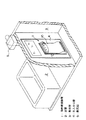
この暖房乾燥装置1は、図1に示すように、浴室2とこの浴室2に隣接する脱衣室3との間に設けられた出入り口扉4に嵌め込まれたもので、その正面側を脱衣室3に、その背面側を浴室2にそれぞれ臨むよう配置されている。なお、この浴室2の天井側には浴室2を換気する換気扇5が設置されている。
【0015】
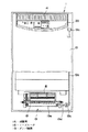
この暖房乾燥装置1の構造を図2乃至図3を参照して説明する。この暖房乾燥装置1は、縦長扁平の筐体10を有し、この筐体10の幅方向中央には正面側と背面側に仕切る取り付け板11が配置されている。この取り付け板11の背面側にはこれと対向してシェルフガード12aで囲われた遠赤外線ヒータ12が配置され、他方、取り付け板11の正面側には同じくこれと対向して遮熱板13が配置されている。これにより、遠赤外線ヒータ12の輻射熱が浴室2側に輻射され、他方、この輻射熱が遮熱板13により脱衣室3側に逃げないようにしている。
【0016】
また、この筐体10の上部正面には空気の吸い込み口14が設置される一方、筐体10の下部正面及び背面には送風機(シロッコファン)15を間にしてそれぞれ空気の吹き出し口16,17が設けられている。この送風機15の稼働により、吸い込み口14を通じて脱衣室3側の空気が筐体10内に流れ込み、この流れ込んだ空気が取り付け板11と遮熱板13の間を流れて、それぞれ各吹き出し口16,17から吹き出されるようになっている。また、この送風機15の下方には、コイル状にフィンが巻回されたシーズヒータ18が設置されており、このシーズヒータ18に通電するとき、この流れ込んだ空気が加温される(図4の1点鎖線矢印)。
【0017】
このように送風機15及びシーズヒータ18により温風が吹き出されるが、この温風の吹き出し方向を選択的に切り換える機構としてダンパ機構19を設けている。このダンパ機構19は、図2及び図4に示すように、一端を軸支した操作レバー19aと、この操作レバー19aにより上下する連結ロッド19bと、この連結ロッド19bの上下動により回転する連結アーム19cと、この連結アーム19cの回転により回転するダンパ軸19dと、このダンパ軸19dに固着されたダンパ19eとにより構成されている。ここで、ダンパ19eは、図4に示すように、断面略L字状に形成され、ダンパ軸19dの回転により正面側の吹き出し口16に向かって対向したり(実線)、或いは、背面側の吹き出し口17に向かって対向し(2点鎖線)、浴室2側或いは脱衣室3側にそれぞれ吹き出し空気を切り換えるようになっている。
【0018】
本実施形態に係る暖房乾燥装置1の構造は前述の如く構成されているが、これらの各種構成機器5,12,15,18は1個又は複数個を組み合わせて選択的に稼働される。この選択的な稼働により各種運転モードが実現され、この操作を操作パネル20で行う。この操作パネル20を図5を参照して説明する。
【0019】
この操作パネル20には、電源スイッチ21、スタートスイッチ22、運転切換スイッチ23、衣類乾燥モードのタイマスイッチ24、同じく衣類乾燥モードの連続・間欠運転切換スイッチ25の各種スイッチ群と、動作異常、スタート及び一時停止、遠赤暖房、温風暖房、遠赤温風暖房、送風、衣類乾燥、タイマ、連続及び間欠運転をそれぞれ表示するランプ群32が設けられており、これらの各種スイッチ群で暖房乾燥装置1を制御するとともに、スイッチ群で選択されたものを各種ランプ群32で表示する。
【0020】
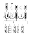
次に、これらの各種スイッチ群及びランプ群により制御される回路構成を図6を参照して説明する。即ち、前記各種スイッチ21〜25からの信号に基づきマイクロコンピュータ構成のCPU26が判定し、この判定に基づき、遠赤外線ヒータ駆動回路27、シーズヒータ駆動回路28、送風機駆動回路29、ランプ群駆動回路30及び換気扇駆動回路31を介して遠赤外線ヒータ12、シーズヒータ18、送風機15、ランプ群32及び換気扇5を選択的に駆動制御する。
【0021】
この駆動制御のうち、各種スイッチ21〜25により制御される各種運転モードを図7及び図8のフローチャートに基づいて説明する。
【0022】
まず、電源スイッチ21をオンして暖房乾燥装置1に電源を投入する。しかる後、スタートスイッチ22がオンしているか、また、運転モードが何れとなっているかを判定する(S1〜S6)。ここで、遠赤暖房モードが選択されているときは、遠赤外線ヒータ12を稼働する(S7)。これにより、浴室2がその側面全体から輻射暖房される。なお、このスタートスイッチ22でこの遠赤暖房運転及び以下に説明する各種運転を一時停止させたり、或いは、運転を復帰させることができる。
【0023】
温風暖房モードが選択されているときは、シーズヒータ18及び送風機15を稼働する(S8)。この温風暖房モードでダンパ機構19により浴室2側の吹き出し口17に空気を導くよう操作されているときは、温風が浴室2の床側に吹き出され、足下の温風暖房が行われる。他方、脱衣室3側の吹き出し口16に空気を導くよう操作されているときは、脱衣室3の温風暖房が行われる。
【0024】
遠赤温風暖房モードが選択されているときは、前述の遠赤暖房と温風暖房の両者が同時に行われる。即ち、遠赤外線ヒータ12、シーズヒータ18及び送風機15が稼働し(S9)、遠赤輻射と温風吹き出しが同時に行われるため、外気温度が低くなる冬期等に有効な運転となる。
【0025】
送風モードが選択されているときは、送風機15を稼働する(S10)。ここで、ダンパ機構19により浴室2側の吹き出し口17が開放されているときは、脱衣室3の空気が浴室2に吹き出され、涼風が浴室2に循環する。他方、脱衣室3側の吹き出し口16が開放しているときは、脱衣室3内で涼風が循環する。この運転モードは夏期の如く室内温度が高くなるとき特に有効なものとなる。
【0026】
このような遠赤暖房モード、温風暖房モード、遠赤温風暖房モード及び送風モードは入浴時間が60分程度であることを考慮し、その運転開始時間から60分で終了する(S11〜S13)。
【0027】
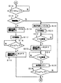
他方、衣類乾燥モードが選択されているときは、図8に示すように、タイマスイッチ24で乾燥時間がセットされ(1時間〜12時間)、かつ、連続・間欠運転切換スイッチ25により連続運転と間欠運転の何れが選択される(S14,S15)。ここで、連続運転が選択されているときは、遠赤外線ヒータ12及び換気扇5がタイマのセット時間に亘って稼働する(S16〜S19)。これにより、浴室2に吊された衣類等が加熱され、また、この加熱により発生する湿気が屋外に排出され、衣類乾燥が行われる。他方、間欠運転が選択されているときは、まず、45分間に亘って遠赤外線ヒータ12を稼働し、衣類を加熱する(S20〜S23)。その後、15分間に亘って換気扇5を稼働し、湿気を屋外に排出する(S23〜S25)。このような1時間サイクルの乾燥操作をタイマのセット時間、例えばセット時間が3時間であれば3回に亘って行い衣類乾燥を行う(S26)。
【0028】
このように、本実施形態に係る暖房乾燥装置1は、浴室2の出入り口扉4に嵌め込まれ、遠赤外線ヒータ12により浴室2の側面から輻射暖房するため、浴室2全体を暖房できるし、また、冬期の如く温度が低いときは足下温風暖房もでき、浴室暖房に好適なものとなっている。
【0029】
また、送風モードにより脱衣室3の空気を浴室2に強制送風でき、浴室に涼風を循環することができる。
【0030】
更に、ダンパ機構19により浴室2に隣接する脱衣室3に温風或いは涼風を送風することができる。
【0031】
なお、この実施形態では、遠赤外線ヒータ12、シーズヒータ18、送風機15、ランプ群32及び換気扇5の選択制御手段としてマイクロコンピュータ構成のCPU26を用いているが、これに限られるものではなく、タイマ、リレースイッチ等を組み込んだ電気回路によりこの選択制御手段を構成するようにしても良い。
【0032】
図9は本発明に係る暖房乾燥装置1の第2実施形態を示すものである。前記実施形態では、暖房乾燥装置1を浴室2の出入り口扉4に嵌め込む例を説明したが、本実施形態では移動手段であるキャスタ33を筐体10の底面に取り付け、暖房乾燥装置1を移動自在に構成している。
【0033】
この実施形態によれば、前述の如き浴室2の暖房或いは乾燥に限らず、その他の部屋、例えば居間等の簡易的な暖房装置としても使用できる。なお、その他の構成、作用は前記第1実施形態と同様である。
【0034】
【発明の効果】
以上説明したように、本発明によれば、暖房乾燥装置を浴室の出入り口扉に設置するときは、浴室を輻射暖房及び温風暖房でき、浴室全体を確実に暖房することができるし、また、浴室を衣類乾燥空間として利用できる。更に、送風機のみを稼働することにより、浴室内に涼風を循環させることもできる。更にまた、ダンパ機構によりこの浴室に隣接する脱衣室側の暖房等もできる。更にまた、筐体にキャスタを取り付けることにより、移動自在となり、浴室以外の部屋、例えば居間等の簡易的な暖房装置としても利用できる。
【図面の簡単な説明】
【図1】第1実施形態に係る暖房乾燥装置の設置状態を示す斜視図
【図2】第1実施形態に係る暖房乾燥装置の一部切り欠き正面図
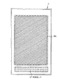
【図3】第1実施形態に係る暖房乾燥装置の背面図
【図4】第1実施形態に係る暖房乾燥装置の断面図
【図5】第1実施形態に係る暖房乾燥装置の操作パネルを示す正面図
【図6】第1実施形態に係る暖房乾燥装置の駆動制御回路を示すブロック図
【図7】第1実施形態に係る暖房乾燥装置の制御フローチャートの1
【図8】第1実施形態に係る暖房乾燥装置の制御フローチャートの2
【図9】第2実施形態に係る暖房乾燥装置の要部を示す側面図
【符号の説明】
1…暖房乾燥装置、2…浴室、3…脱衣室、4…出入り口扉、5…換気扇、10…筐体、12…遠赤外線ヒータ、14…吸い込み口、15…送風機、16,17…吹き出し口、18…シーズヒータ、26…CPU。[0001]
TECHNICAL FIELD OF THE INVENTION
The present invention relates to a heating and drying device having a function of heating a bathroom and the like and a function of drying clothes.
[0002]
[Prior art]
Conventionally, as this type of heating / drying apparatus, a heating / drying apparatus installed on a ceiling of a bathroom or the like is known.
[0003]
This heating and drying device is equipped with a heater and a blower, and the air in the bathroom is sucked into the device body by the blower, and the sucked air is heated by the heater and circulated in the bathroom. . The bathroom is heated by the circulating heated air.
[0004]
On the other hand, when the bathroom is dried, a ventilation fan is operated in addition to the heater and the blower, and moisture is discharged to the outside simultaneously with the heating of the bathroom to dry clothes.
[0005]
[Problems to be solved by the invention]
However, in the conventional heating and drying apparatus, since the bathroom is heated by circulating the heated air from the ceiling, high-temperature circulating air easily stays on the ceiling side of the bathroom, and therefore, the temperature on the ceiling side is high. However, the temperature on the floor of the bathroom was low, and it could not be said that the bathroom was comfortable.
[0006]
Also, in the bathroom drying, most of the high temperature of the air discharged outside by the ventilation fan also stays on the ceiling side of the bathroom, so that the drying temperature is low and the drying time of clothes etc. is prolonged. Had problems.
[0007]
Furthermore, this heating / drying apparatus is dedicated to a bathroom, and cannot circulate heated air to a dressing room or the like adjacent to the bathroom.
[0008]
An object of the present invention is to provide a heating and drying apparatus that can surely heat the floor side of a bathroom and the like, shorten the drying time, and further heat a dressing room adjacent to the bathroom and the like in view of the conventional problems. Is to do.
[0009]
[Means for Solving the Problems]
In order to solve the above-described problems, the present invention provides a heating / drying apparatus according to the present invention, which includes a mounting plate that partitions the inside of a vertically long housing into a front side and a back side, and a housing that is installed on the back side inside the housing. A far-infrared heater that radiates far-infrared rays from the back, an air flow path formed on the front side inside the housing, a blower that sucks air outside the housing into this flow path , and air that is sucked in by the blower And a damper mechanism for selectively guiding the air heated by the sheath heater to an outlet at the lower front side or an outlet at the lower rear side of the housing.
[0010]
When this heating and drying device is installed at the entrance door of the bathroom, and when the outlet on the bathroom side is opened by the damper mechanism, radiant heating of the bathroom is performed by the far-infrared heater, and warm air heating under the feet is performed by the sheath heater and the blower. Done. On the other hand, when the outlet on the undressing room side is opened by the damper mechanism, warm air heating on the undressing room side is performed.
[0011]
When drying the bathroom, the far infrared heater and the ventilation fan are operated. Thus, the clothes and the like suspended in the bathroom are heated by the far-infrared heater, and the moisture generated from the clothes is discharged outside by the ventilation fan.
[0012]
In the above, an example in which the heating and drying device is installed at the entrance door of the bathroom has been described. However, the present invention is not limited to this. It can be used as a simple heating device.
[0013]
BEST MODE FOR CARRYING OUT THE INVENTION
1 to 8 show a first embodiment of a heating / drying apparatus according to the present invention. FIG. 1 is a perspective view showing an installed state of the heating / drying apparatus, and FIG. 2 is a partially cutaway front view of the heating / drying apparatus. 3 is a rear view of the heating / drying device, FIG. 4 is a cross-sectional view of the heating / drying device, FIG. 5 is a front view showing an operation panel of the heating / drying device, FIG. 6 is a block diagram showing a drive control circuit of the heating / drying device, FIG. 7 is a
[0014]
As shown in FIG. 1, the heating /
[0015]
The structure of the heating and
[0016]
An
[0017]
As described above, hot air is blown out by the
[0018]
Although the structure of the heating and drying
[0019]
The
[0020]
Next, a circuit configuration controlled by these various switch groups and lamp groups will be described with reference to FIG. That is, the CPU 26 of the microcomputer makes a determination based on signals from the
[0021]
Among the drive controls, various operation modes controlled by the
[0022]
First, the
[0023]
When the hot air heating mode is selected, the
[0024]
When the far-red hot air heating mode is selected, both the far-red heating and the hot air heating described above are performed simultaneously. That is, the far-
[0025]
When the blow mode is selected, the
[0026]
Considering that the bathing time is about 60 minutes, the far-infrared heating mode, the warm-air heating mode, the far-red-hot air heating mode, and the blowing mode end in 60 minutes from the operation start time (S11 to S13). ).
[0027]
On the other hand, when the clothes drying mode is selected, as shown in FIG. 8, the drying time is set by the timer switch 24 (1 hour to 12 hours), and the continuous / intermittent
[0028]
As described above, the heating and drying
[0029]
Further, the air in the
[0030]
Furthermore, warm air or cool air can be sent to the
[0031]
Although the far-
[0032]
FIG. 9 shows a second embodiment of the heating and drying
[0033]
According to this embodiment, it is not limited to heating or drying the
[0034]
【The invention's effect】
As described above, according to the present invention, when the heating / drying device is installed at the entrance door of the bathroom, the bathroom can be radiated and heated with hot air, and the entire bathroom can be reliably heated. The bathroom can be used as a clothes drying space. Further, by operating only the blower, cool air can be circulated in the bathroom. Furthermore, the damper mechanism can be used to heat the dressing room adjacent to the bathroom. Furthermore, by attaching a caster to the housing, the housing becomes movable and can be used as a simple heating device for a room other than the bathroom, for example, a living room.
[Brief description of the drawings]
FIG. 1 is a perspective view showing an installation state of a heating and drying apparatus according to a first embodiment; FIG. 2 is a partially cutaway front view of the heating and drying apparatus according to the first embodiment; FIG. FIG. 4 is a cross-sectional view of the heating / drying apparatus according to the first embodiment. FIG. 5 is a front view showing an operation panel of the heating / drying apparatus according to the first embodiment. FIG. 6 is a first embodiment. FIG. 7 is a block diagram illustrating a drive control circuit of the heating / drying apparatus according to the first embodiment. FIG. 7 is a control flowchart of the heating / drying apparatus according to the first embodiment.
FIG. 8 is a second control flowchart of the heating / drying apparatus according to the first embodiment.
FIG. 9 is a side view showing a main part of a heating and drying apparatus according to a second embodiment.
DESCRIPTION OF
Claims (3)
ことを特徴とする暖房乾燥装置。 A mounting plate that partitions the inside of the vertically long housing into a front side and a back side, a far-infrared heater installed on the back side of the inside of the housing and radiating far-infrared rays from the back of the housing, and an inside of the housing. A flow path of air formed on the front side, a blower that sucks air outside the housing into the flow path, a sheath heater that heats the air sucked by the blower, and an air heated by the sheath heater. A heating / drying apparatus comprising: a damper mechanism for selectively guiding a blow port at a lower portion on the front side or a blow port at a lower portion on the rear side of the housing.
ことを特徴とする請求項1記載の暖房乾燥装置。 It is attached to the housing to the entrance door of a bathroom with a ventilation fan, the far-infrared heater, the blower, to have one or a control means for controlling to operate by combining a plurality of the sheathed heater or the ventilators The heating and drying apparatus according to claim 1, wherein:
ことを特徴とする請求項1記載の暖房乾燥装置。The heating and drying apparatus according to claim 1, wherein a caster (moving means) is attached to the housing.
Priority Applications (1)
| Application Number | Priority Date | Filing Date | Title |
|---|---|---|---|
| JP25393195A JP3554618B2 (en) | 1995-09-29 | 1995-09-29 | Heating and drying equipment |
Applications Claiming Priority (1)
| Application Number | Priority Date | Filing Date | Title |
|---|---|---|---|
| JP25393195A JP3554618B2 (en) | 1995-09-29 | 1995-09-29 | Heating and drying equipment |
Publications (2)
| Publication Number | Publication Date |
|---|---|
| JPH0996489A JPH0996489A (en) | 1997-04-08 |
| JP3554618B2 true JP3554618B2 (en) | 2004-08-18 |
Family
ID=17258015
Family Applications (1)
| Application Number | Title | Priority Date | Filing Date |
|---|---|---|---|
| JP25393195A Expired - Fee Related JP3554618B2 (en) | 1995-09-29 | 1995-09-29 | Heating and drying equipment |
Country Status (1)
| Country | Link |
|---|---|
| JP (1) | JP3554618B2 (en) |
Families Citing this family (5)
| Publication number | Priority date | Publication date | Assignee | Title |
|---|---|---|---|---|
| CN105318402B (en) * | 2015-05-26 | 2018-01-02 | 高乃鑫 | Pipeline heating Multifunctional air heater for bathroom |
| CN105318403B (en) * | 2015-07-28 | 2017-12-08 | 高乃鑫 | Lower heating super bath and lower heating type separate body bath warmer |
| CN105953533A (en) * | 2016-06-17 | 2016-09-21 | 瑞基科技发展有限公司 | Steam drying warehouse for denitration catalysts |
| CN105972945A (en) * | 2016-06-17 | 2016-09-28 | 瑞基科技发展有限公司 | Denitration catalyst steam drying chamber |
| CN109914081A (en) * | 2019-01-18 | 2019-06-21 | 香港丽纯科技有限公司 | Far infrared cleaning device and its safe start and stop method |
-
1995
- 1995-09-29 JP JP25393195A patent/JP3554618B2/en not_active Expired - Fee Related
Also Published As
| Publication number | Publication date |
|---|---|
| JPH0996489A (en) | 1997-04-08 |
Similar Documents
| Publication | Publication Date | Title |
|---|---|---|
| JP2006029752A (en) | Bathroom air conditioner | |
| WO2006009171A1 (en) | Bathroom air conditioner | |
| JPH0956992A (en) | Clothing drying device | |
| JP5538621B2 (en) | Bathroom Dryer | |
| JP3554618B2 (en) | Heating and drying equipment | |
| JP2001062194A (en) | Clothing drier | |
| JP3959181B2 (en) | Heat exchange ventilation system | |
| JP4715393B2 (en) | Air conditioner | |
| US3021696A (en) | Vent and exhaust arrangement for air conditioning unit | |
| JP3128265B2 (en) | Air conditioner with clothes drying function | |
| JP2001116275A (en) | Bathroom heater | |
| JP4802596B2 (en) | Bathroom air conditioner and bathroom | |
| JP3197595B2 (en) | Bathroom air conditioner | |
| JP3157494B2 (en) | Bathroom heating dryer | |
| JP3965730B2 (en) | Bathroom heating dryer | |
| JP3015576B2 (en) | Bathroom air conditioner | |
| JP2001289450A (en) | Bathroom heater | |
| KR101491807B1 (en) | Warm wind blow apparatus having function of dehumidification | |
| JP3129996B2 (en) | Bathroom heating system with heating function for other rooms | |
| JP2002089921A (en) | Ventilation equipment | |
| JP2005221178A (en) | Forced simultaneous air supply and exhaust type ventilating device | |
| JP2007032874A (en) | Air conditioner | |
| JP2626157B2 (en) | Air conditioner | |
| JP2000254398A (en) | Bathroom air conditioner | |
| JPH07104009B2 (en) | Air conditioner |
Legal Events
| Date | Code | Title | Description |
|---|---|---|---|
| TRDD | Decision of grant or rejection written | ||
| A01 | Written decision to grant a patent or to grant a registration (utility model) |
Free format text: JAPANESE INTERMEDIATE CODE: A01 Effective date: 20040427 |
|
| A61 | First payment of annual fees (during grant procedure) |
Free format text: JAPANESE INTERMEDIATE CODE: A61 Effective date: 20040510 |
|
| R150 | Certificate of patent or registration of utility model |
Free format text: JAPANESE INTERMEDIATE CODE: R150 |
|
| R250 | Receipt of annual fees |
Free format text: JAPANESE INTERMEDIATE CODE: R250 |
|
| FPAY | Renewal fee payment (event date is renewal date of database) |
Free format text: PAYMENT UNTIL: 20090514 Year of fee payment: 5 |
|
| FPAY | Renewal fee payment (event date is renewal date of database) |
Free format text: PAYMENT UNTIL: 20100514 Year of fee payment: 6 |
|
| LAPS | Cancellation because of no payment of annual fees |