EP0155994B1 - Gaserzeugungsanlage, insbesondere für Orbitalstationen und Satelliten - Google Patents
Gaserzeugungsanlage, insbesondere für Orbitalstationen und Satelliten Download PDFInfo
- Publication number
- EP0155994B1 EP0155994B1 EP84112442A EP84112442A EP0155994B1 EP 0155994 B1 EP0155994 B1 EP 0155994B1 EP 84112442 A EP84112442 A EP 84112442A EP 84112442 A EP84112442 A EP 84112442A EP 0155994 B1 EP0155994 B1 EP 0155994B1
- Authority
- EP
- European Patent Office
- Prior art keywords
- gas
- gas producing
- producing installation
- anyone
- chamber
- Prior art date
- Legal status (The legal status is an assumption and is not a legal conclusion. Google has not performed a legal analysis and makes no representation as to the accuracy of the status listed.)
- Expired
Links
- 238000009434 installation Methods 0.000 title claims 15
- 239000007789 gas Substances 0.000 claims description 83
- 238000000034 method Methods 0.000 claims description 72
- UFHFLCQGNIYNRP-UHFFFAOYSA-N Hydrogen Chemical compound [H][H] UFHFLCQGNIYNRP-UHFFFAOYSA-N 0.000 claims description 26
- 238000000926 separation method Methods 0.000 claims description 25
- 239000003054 catalyst Substances 0.000 claims description 13
- KDLHZDBZIXYQEI-UHFFFAOYSA-N Palladium Chemical compound [Pd] KDLHZDBZIXYQEI-UHFFFAOYSA-N 0.000 claims description 12
- 239000000203 mixture Substances 0.000 claims description 12
- 229910052763 palladium Inorganic materials 0.000 claims description 6
- 238000003421 catalytic decomposition reaction Methods 0.000 claims description 4
- 239000012528 membrane Substances 0.000 claims description 4
- 238000006243 chemical reaction Methods 0.000 claims description 2
- 239000007788 liquid Substances 0.000 claims description 2
- 229910052751 metal Inorganic materials 0.000 claims description 2
- 239000002184 metal Substances 0.000 claims description 2
- 238000004886 process control Methods 0.000 claims description 2
- 230000001360 synchronised effect Effects 0.000 claims description 2
- OAKJQQAXSVQMHS-UHFFFAOYSA-N Hydrazine Chemical compound NN OAKJQQAXSVQMHS-UHFFFAOYSA-N 0.000 description 31
- IJGRMHOSHXDMSA-UHFFFAOYSA-N nitrogen Substances N#N IJGRMHOSHXDMSA-UHFFFAOYSA-N 0.000 description 30
- 239000001257 hydrogen Substances 0.000 description 15
- 229910052739 hydrogen Inorganic materials 0.000 description 15
- 229910052757 nitrogen Inorganic materials 0.000 description 15
- 229910001873 dinitrogen Inorganic materials 0.000 description 5
- 238000013461 design Methods 0.000 description 4
- QJGQUHMNIGDVPM-UHFFFAOYSA-N nitrogen(.) Chemical compound [N] QJGQUHMNIGDVPM-UHFFFAOYSA-N 0.000 description 4
- 150000002431 hydrogen Chemical class 0.000 description 3
- 238000012546 transfer Methods 0.000 description 3
- 238000010276 construction Methods 0.000 description 2
- 238000002474 experimental method Methods 0.000 description 2
- 238000010438 heat treatment Methods 0.000 description 2
- 239000011261 inert gas Substances 0.000 description 2
- 238000005086 pumping Methods 0.000 description 2
- 238000011144 upstream manufacturing Methods 0.000 description 2
- LONQTZORWVBHMK-UHFFFAOYSA-N [N].NN Chemical group [N].NN LONQTZORWVBHMK-UHFFFAOYSA-N 0.000 description 1
- 238000000354 decomposition reaction Methods 0.000 description 1
- 238000011161 development Methods 0.000 description 1
- 230000018109 developmental process Effects 0.000 description 1
- 238000009792 diffusion process Methods 0.000 description 1
- 238000005516 engineering process Methods 0.000 description 1
- 238000000605 extraction Methods 0.000 description 1
- 239000000446 fuel Substances 0.000 description 1
- 238000011990 functional testing Methods 0.000 description 1
- 239000011810 insulating material Substances 0.000 description 1
- 238000007726 management method Methods 0.000 description 1
- 238000004519 manufacturing process Methods 0.000 description 1
- 230000003287 optical effect Effects 0.000 description 1
- 230000008439 repair process Effects 0.000 description 1
- 230000029058 respiratory gaseous exchange Effects 0.000 description 1
- 238000012360 testing method Methods 0.000 description 1
Images


Classifications
-
- B—PERFORMING OPERATIONS; TRANSPORTING
- B01—PHYSICAL OR CHEMICAL PROCESSES OR APPARATUS IN GENERAL
- B01J—CHEMICAL OR PHYSICAL PROCESSES, e.g. CATALYSIS OR COLLOID CHEMISTRY; THEIR RELEVANT APPARATUS
- B01J7/00—Apparatus for generating gases
- B01J7/02—Apparatus for generating gases by wet methods
-
- B—PERFORMING OPERATIONS; TRANSPORTING
- B64—AIRCRAFT; AVIATION; COSMONAUTICS
- B64G—COSMONAUTICS; VEHICLES OR EQUIPMENT THEREFOR
- B64G1/00—Cosmonautic vehicles
- B64G1/22—Parts of, or equipment specially adapted for fitting in or to, cosmonautic vehicles
- B64G1/46—Arrangements or adaptations of devices for control of environment or living conditions
- B64G1/48—Arrangements or adaptations of devices for control of environment or living conditions for treatment of the atmosphere
Definitions
- the invention relates to a gas generation system, in particular for orbital stations and satellites, in which gases are generated on the basin of the chemical reaction and / or catalytic decomposition of a preferably liquid energy source and the gas mixture thus generated is broken down into its components by means of a downstream separating device.
- the use of regenerative processes is increasingly being attempted, in order to save weight and space on consumables, in particular with regard to longer mission times.
- This also applies to the supply of nitrogen and hydrogen gas in such spacecraft.
- the nitrogen is used as a breathing air admixture in the living and working area of the astronauts, as an inert gas for scientific experiments and in cold gas position control engines.
- Hydrogen is also frequently used for the latter purpose, which, when used as cold gas, has a significantly higher specific impulse than nitrogen.
- hydrogen is used in fuel cells and also in scientific experiments in space.
- inert gas generators for these fields of application, which consist of a hydrazine tank, a gas generator and a hydrogen diffusion and separation device.
- hydrogen permeation plants are already known which are used for the production of high-purity hydrogen and for the separation of hydrogen from hydrogen-nitrogen mixtures. These latter devices work with vacuum systems as well as with electrical heating.
- the object of the invention is to design a gas generation system of the type mentioned at the outset in such a way that, while maintaining the high functional reliability required for space systems, it has a compact design suitable for such systems and at the same time has the greatest possible time separation and delivery rate of the desired gas components.
- this system should be as versatile as possible.
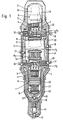
- the gas generation plant shown in FIG. 1 is a modular system for generating and separating nitrogen and hydrogen gas from hydrazine.
- the system initially consists of two separate process chambers 1 and 2, which are arranged opposite one another and which are connected to one another via a third chamber 3.
- the two process chambers 1 and 2 each include one or more, in the case of the exemplary embodiment shown here, two gas generators 4 and 5 or 6 and 7, one post-catalyst 8 and 9 and two hydrogen separation units 10 and 11 and 12, respectively and 13.
- a further hydrogen gas separation unit 14 or 15, which is accommodated in the interior of the third chamber 3, is also assigned to the process chambers.
- the arrangement comprises a series of magnetically actuated valves 16 to 23, which are used for gas routing and process control and whose function will be discussed in more detail.
- the arrangement described here also includes a supply unit 24, via which the gas generators 4 to 7 are supplied with the energy source.
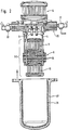
- FIG. 2 a large part of the system components, namely the gas generators 4 and 5, the assembly groups consisting of the two separation units 10 and 11 and the post-catalyst 8, the further separation unit 14 and finally the two valves 17 and 22 mounted on a common flange 25.
- the gas generators 6 and 7 On the flange 26 are the gas generators 6 and 7, the separation units 12, 13 and 15, the post-catalyst in an analogous manner 9 and the valves 19 and 20 mounted.
- FIGS. 1 and 2 also show, the two process chambers 1 and 2 are each surrounded by a hood 27 and 28, in each of which an annular electrical heating element 29 and 30 is arranged.
- the hoods 27 and 28, the chamber 3 and the cylinder unit 24 are embedded in an almost completely closed jacket 31 made of insulating material, which in turn is surrounded by a metal shell 32.
- the insulating jacket 31 accommodates both the remaining valves, which are not arranged on the flanges 25 and 26, and the majority of the connecting lines 33 between the individual process rooms.
- Fig. 3 shows in detail the arrangement of the two separation units 10 and 11, which are upstream or downstream of the post-catalyst 8 and together with this form an assembly unit.
- the separation units consisting of palladium may fulfill this function sufficiently.
- the construction of the post-catalyst which is already shown in FIG. 2, is omitted in this figure, which is composed of several disks 34, which in turn each consist of sieve mesh held between circular perforated plates.
- the separating units 10 and 11 and, in an analogous manner also the separating units 12 and 13, are each formed by a number of separating tubes 35 made of palladium, which are combined into cylindrical units by circular perforated plates 36.
- separating membranes 37 also made of palladium, which are curved outwards and are embedded in annular retaining rings 38.
- the two removal points 39 and 40 for the hydrogen gas collecting below the separation membranes can also be seen.
- FIGS. 1 and 2 also show, the structure of the two separation units 14 and 15 essentially corresponds to that described above; due to a larger number of separating tubes, only their diameter is larger than that of the separating units 10 to 13.
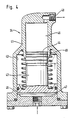
- FIG. 4 shows in detail the structure of the feed unit 24 for the energy source, in the present case for the hydrazine.
- a punch 43 is arranged in a longitudinally displaceable manner in a recess 42 located inside a housing 41.
- the latter carries at one end a piston 44 and at the opposite end a second piston 45, the diameter of which is larger than that of the piston 44.
- Both pistons move in corresponding piston chambers 46 and 47, of which the piston chamber 46 belonging to the smaller piston 44 is connected via a ball valve 48 to the storage container for the energy carrier, not shown here.
- this piston chamber 46 is connected to the gas generators 4 to 7 via the solenoid valve 23 and a branch of the line system 33.
- the piston chamber 47 can be supplied with process gas by means of the solenoid valve 16 and another branch of the line system 33.
- the feed unit 24 has a spiral spring 49 which surrounds the plunger 43 and acts on the piston 45.
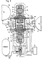
- FIG. 5 shows a schematic representation of the structure of a largely autonomous gas supply system for nitrogen and hydrogen gas, which is essentially based on the gas generation system described with reference to FIGS. 1 to 4. This arrangement is shown with its most important components in the middle of FIG. 5.
- the operation of the gas generation system according to the invention will now be described with reference to the arrangement shown in FIG. 5.
- the system can, except for the required electronic switching pulses for the process computer, largely autonomously, i. H. independent of the supply of external energy.
- hydrazine is briefly conveyed into the gas generators 4, 5 or 6, 7 by means of the feed unit 24.
- a start pulse for example the application of a compressed gas
- the one generated by catalytic decomposition of the hydrazine Nitrogen / hydrogen gas mixture enters the associated process chamber, in this case it is process chamber 1 first.
- the two separation units 10 and 11 already partially separate the hydrogen from the nitrogen / hydrogen mixture.
- the post-catalyst 8 also contained in process chamber 1 also ensures that any residual N2H4 parts still present in the gas mixture are further broken down into the components nitrogen and hydrogen.
- the gas mixture which now has a higher nitrogen content than the starting mixture, passes through the changeover valve 22 to the third chamber 3, which acts as an intermediate collector Alternating cycle (processor-controlled) generates a constant gas change over the post-catalyst and thereby significantly accelerates the rest of NZH4 decay in the process chamber.
- the separating units 14 and 15 arranged in the intermediate collector 3 then ensure the complete separation of the remaining hydrogen from the process mixture.
- the separated hydrogen gas collects both in the pre-separation units 10 and 11 and in the post-separation units 14 and 15 below the palladium membranes and is fed to the hydrogen gas collection tank 51 via the changeover valves 17 and 18.
- the nitrogen gas remaining in the intermediate collector 3 is discharged via the valve 21 into the nitrogen gas collecting tank 52.
- the changeover valve 19 is used to remove the hydrogen gas from the separating units 12 and 13 and the valve 20 for the subsequent transfer of the nitrogen-enriched process gas into the intermediate collector 3, again alternately upstream and downstream of the post-catalyst.
- the operating pressure of one chamber d. H. use the process gas to provide the required pumping capacity.
- a - program-controlled - alternating cycle switching of the extraction valves 17 and 19 for the discharge of the separated hydrogen gas from the respective separation units into the corresponding collecting tank ensures that there is sufficient gas movement on the separating palladium surfaces, which is an essential prerequisite for a thorough separation of the components are from the process gas mixture.
- the hydrogen gas can be discharged from the process chambers and the intermediate collector into the collecting tank 51 during the entire process. Since gas first flows from the first process chamber into the intermediate collector for a period of half a process period, and then also from the second process chamber for the same length of time and then there is a pause of the same duration, a sufficient dwell time in the intermediate collector is ensured without the Back pressure in this would increase too high and could influence the hydrogen gas withdrawal from the two process chambers.
- the removal of the nitrogen gas from the intermediate collector via the valve 21 can either take place for a certain time at the end of the dwell time of the process gas in the intermediate collector or can be initialized by the signal of a pressure switch 53 installed in the intermediate collector as soon as a predetermined pressure threshold value has been exceeded.
- the residence time of the gas in the intermediate collector can be extended with an otherwise identical cycle time.
- the length of this dwell time can be controlled, for example, by means of a sensor in the intermediate collector that is sensitive to hydrogen, which registers the hydrogen depletion in this space and delivers a corresponding switching pulse to the valve 21 for the nitrogen removal at a predetermined threshold value.
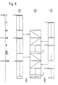
- Fig. 6 the above-described operating cycle of the arrangement according to the invention is shown once again in a synchronous optical representation.
- the time axis on which the start of the process (t 0), the period T between two loads of a Pro is plotted on the left edge of the picture zeßhunt marked with hydrazine and various process stages up to VIII.
- Point I marks the start of the process, optionally initiated by supplying the supply unit 24 with pressure (20 bar) from outside, in which process chamber 1 is charged with hydrazine.
- Point 11 marks the same process for process chamber 2, approximately after half the operating time of process chamber 1 or at T / 3.
- the removal time for chamber 1 begins, ie the time in which the process gas which has already been enriched with nitrogen is transferred to the intermediate collector 3.
- this process begins with the process chamber 3, at the same time the gas generators of the process chamber 1 are again charged with hydrazine, while at point V the process chamber 2 is again supplied with hydrazine.
- the design of the arrangement according to the invention as a two-chamber system not only enables a very compact construction of such a gas generation system, but at the same time an improved system redundancy is achieved.
- FIG. 7 An arrangement is shown in which a total of 60 gas generation plants of the type shown in FIG. 1, combined in six triangular clusters of 10 plants each, are accommodated in the cylindrical structure 55 of an orbital station.
- the integrated arrangement of a large part of the components on the two flanges 25 and 26 not only enables quick disassembly and thus replacement of these components, but that, for example for test purposes, by simply inserting intermediate rings between a flange and the associated hood or between a flange and the intermediate collector any enlargement of the individual chambers can take place. Furthermore, it is possible in a particularly simple manner to subject some of the components to a functional test in order to then gradually complete the arrangement.
Landscapes
- Chemical & Material Sciences (AREA)
- Engineering & Computer Science (AREA)
- Environmental & Geological Engineering (AREA)
- Health & Medical Sciences (AREA)
- Life Sciences & Earth Sciences (AREA)
- Biodiversity & Conservation Biology (AREA)
- Chemical Kinetics & Catalysis (AREA)
- Environmental Sciences (AREA)
- General Health & Medical Sciences (AREA)
- Toxicology (AREA)
- Organic Chemistry (AREA)
- Remote Sensing (AREA)
- Aviation & Aerospace Engineering (AREA)
- Separation Using Semi-Permeable Membranes (AREA)
- Feeding, Discharge, Calcimining, Fusing, And Gas-Generation Devices (AREA)
Applications Claiming Priority (2)
| Application Number | Priority Date | Filing Date | Title |
|---|---|---|---|
| DE3408592 | 1984-03-09 | ||
| DE19843408592 DE3408592A1 (de) | 1984-03-09 | 1984-03-09 | Gaserzeugungsanlage, insbesondere fuer orbitalstationen und satelliten |
Publications (2)
| Publication Number | Publication Date |
|---|---|
| EP0155994A1 EP0155994A1 (de) | 1985-10-02 |
| EP0155994B1 true EP0155994B1 (de) | 1987-09-09 |
Family
ID=6229967
Family Applications (1)
| Application Number | Title | Priority Date | Filing Date |
|---|---|---|---|
| EP84112442A Expired EP0155994B1 (de) | 1984-03-09 | 1984-10-16 | Gaserzeugungsanlage, insbesondere für Orbitalstationen und Satelliten |
Country Status (3)
| Country | Link |
|---|---|
| US (1) | US4710359A (enExample) |
| EP (1) | EP0155994B1 (enExample) |
| DE (1) | DE3408592A1 (enExample) |
Families Citing this family (3)
| Publication number | Priority date | Publication date | Assignee | Title |
|---|---|---|---|---|
| GB2200476B (en) * | 1987-01-29 | 1991-02-06 | British Gas Plc | Monitor system |
| JPH07101295B2 (ja) * | 1988-02-23 | 1995-11-01 | 富士写真フイルム株式会社 | 感光物質用包装材料 |
| JP6402020B2 (ja) * | 2014-12-15 | 2018-10-10 | 株式会社Ihiエアロスペース | 推進装置 |
Family Cites Families (15)
| Publication number | Priority date | Publication date | Assignee | Title |
|---|---|---|---|---|
| DD62307A (enExample) * | ||||
| DE45109C (de) * | K. HAUPT in Berlin W., Bülowstr. 39 | Verfahren und Apparate zur ununterbrochenen und selbstthätigen Entwickelung von Gasen unter hohem Druck | ||
| FR1375030A (fr) * | 1962-05-15 | 1964-10-16 | Engelhard Ind Inc | Procédé d'exécution de réactions chimiques en phase gazeuse avec formation d'hydrogène |
| US3278268A (en) * | 1962-08-15 | 1966-10-11 | Engelhard Ind Inc | Method for hydrogen production |
| US3338681A (en) * | 1963-12-18 | 1967-08-29 | Union Carbide Corp | Apparatus for hydrogen generation |
| US3350176A (en) * | 1964-03-24 | 1967-10-31 | Engelhard Ind Inc | Hydrogen generator |
| US3442711A (en) * | 1964-06-22 | 1969-05-06 | Mini Verteidigung | Hydrazine fuel cell |
| US3450500A (en) * | 1965-08-03 | 1969-06-17 | United Aircraft Corp | Method for catalytically reforming hydrogen-containing carbonaceous feed-stocks by simultaneous abstractions through a membrane selectively permeable to hydrogen |
| US3607066A (en) * | 1966-08-30 | 1971-09-21 | Varta Ag | Process for the production of hydrogen and oxygen gases |
| DE1542565B2 (de) * | 1966-10-08 | 1971-09-23 | Varta Ag, 6000 Frankfurt | Verfahren zur erzeugung von reaktionsgasen fuer den betrieb galvanischer brennstoffelemente |
| GB1475090A (en) * | 1973-12-29 | 1977-06-01 | Kernforschungsanlage Juelich | Process for the conversion of water into hydrogen and oxygen |
| US4022018A (en) * | 1975-04-29 | 1977-05-10 | General Electric Company | Mounting system for a thrust generating engine |
| US4157270A (en) * | 1977-09-12 | 1979-06-05 | The United States Of America As Represented By The Secretary Of The Army | Hydrogen gas generator from hydrazine/ammonia |
| US4371500A (en) * | 1979-06-30 | 1983-02-01 | Unique Energy Systems, Inc. | Apparatus for generating hydrogen |
| US4490972A (en) * | 1982-03-29 | 1985-01-01 | Hughes Aircraft Company | Hydrazine thruster |
-
1984
- 1984-03-09 DE DE19843408592 patent/DE3408592A1/de active Granted
- 1984-10-16 EP EP84112442A patent/EP0155994B1/de not_active Expired
-
1985
- 1985-03-08 US US06/709,510 patent/US4710359A/en not_active Expired - Fee Related
Also Published As
| Publication number | Publication date |
|---|---|
| DE3408592C2 (enExample) | 1989-11-09 |
| EP0155994A1 (de) | 1985-10-02 |
| DE3408592A1 (de) | 1985-09-12 |
| US4710359A (en) | 1987-12-01 |
Similar Documents
| Publication | Publication Date | Title |
|---|---|---|
| DE112013004853B4 (de) | Wasserstofferzeugungsvorrichtung und Brennstoffzellensystem mit Wasserstofferzeugungsvorrichtung | |
| DE2304422C2 (de) | Rückstoßtriebwerksystem | |
| DE1248374C2 (de) | Antriebsvorrichtung mit einem Strahltriebwerk | |
| DE4418812C2 (de) | Einfach- und Mehrfachelektrolysezellen sowie Anordnungen davon zur Entionisierung von wäßrigen Medien | |
| EP1364261B2 (de) | System zur automatisierten behandlung von fluiden, mit aneinanderreihbaren, austauschbaren prozessmodulen | |
| DE2927830A1 (de) | Treibstoffdruckerzeugungssystem fuer einen gasgenerator | |
| EP0887306B1 (de) | Vorrichtung zur Erzeugung eines wasserstoffreichen und kohlenmonoxidarmen Gases | |
| EP0029600A1 (de) | Verfahren zur Trennung von Fluiden durch Permeation | |
| DE69114271T2 (de) | Apparat zum erzeugen von wärme. | |
| DE3905172A1 (de) | Erosionsfrei arbeitende strombogentriebwerk-startsteuereinrichtung | |
| EP0155994B1 (de) | Gaserzeugungsanlage, insbesondere für Orbitalstationen und Satelliten | |
| DE102004059776A1 (de) | Brennstoffzellensystem | |
| DE1771052A1 (de) | Brennstoffzellenmodul | |
| DE4308200A1 (en) | Multistorey arrangement - is used for chemical plant reducing space requirements and maintaining ease of access for maintenance | |
| EP0175288B1 (de) | Verfahren zum galvanischen Trennen der elektrolytführenden Sammelleitungen von den Elektrolyträumen eines elektro-chemischen Zellenpaketes | |
| DE4221593A1 (de) | Verfahren und einrichtung zum erzeugen von sauerstoff | |
| WO2001009971A1 (de) | Vorrichtung zum verbinden von mindestens zwei brennstoffzellen-batterien und entsprechend verbundene anlage | |
| EP0012448A1 (de) | Verfahren und Vorrichtung zur selektiven Abtrennung von Wasserstoff aus einer Gasmischung durch Diffusion | |
| EP3348671B1 (de) | Raumflugkörper mit einer antriebsstofferzeugungsvorrichtung | |
| DE69501050T2 (de) | Elektrolyt-aktivierte Batterie | |
| DE2558220A1 (de) | Mehrstufige fluessigkeitsrakete | |
| DE69501219T2 (de) | Elektrolyt-aktivierte Batterie | |
| EP1995352A1 (de) | Verfahren zur Erzeugung eines brennbaren Gemisches | |
| EP3549875A1 (de) | Regeneratives lufterneuerungssystem für einen bemannten raumkörper | |
| EP0128260A1 (de) | Rettungseinrichtung für Unterwasserfahrzeuge |
Legal Events
| Date | Code | Title | Description |
|---|---|---|---|
| PUAI | Public reference made under article 153(3) epc to a published international application that has entered the european phase |
Free format text: ORIGINAL CODE: 0009012 |
|
| AK | Designated contracting states |
Designated state(s): FR IT NL |
|
| 17P | Request for examination filed |
Effective date: 19851019 |
|
| 17Q | First examination report despatched |
Effective date: 19861114 |
|
| GRAA | (expected) grant |
Free format text: ORIGINAL CODE: 0009210 |
|
| AK | Designated contracting states |
Kind code of ref document: B1 Designated state(s): FR IT NL |
|
| ET | Fr: translation filed | ||
| ITF | It: translation for a ep patent filed | ||
| PLBE | No opposition filed within time limit |
Free format text: ORIGINAL CODE: 0009261 |
|
| STAA | Information on the status of an ep patent application or granted ep patent |
Free format text: STATUS: NO OPPOSITION FILED WITHIN TIME LIMIT |
|
| 26N | No opposition filed | ||
| ITTA | It: last paid annual fee | ||
| PGFP | Annual fee paid to national office [announced via postgrant information from national office to epo] |
Ref country code: NL Payment date: 19901031 Year of fee payment: 7 |
|
| PG25 | Lapsed in a contracting state [announced via postgrant information from national office to epo] |
Ref country code: NL Effective date: 19920501 |
|
| NLV4 | Nl: lapsed or anulled due to non-payment of the annual fee | ||
| PGFP | Annual fee paid to national office [announced via postgrant information from national office to epo] |
Ref country code: FR Payment date: 19961030 Year of fee payment: 13 |
|
| PG25 | Lapsed in a contracting state [announced via postgrant information from national office to epo] |
Ref country code: FR Free format text: THE PATENT HAS BEEN ANNULLED BY A DECISION OF A NATIONAL AUTHORITY Effective date: 19971031 |
|
| REG | Reference to a national code |
Ref country code: FR Ref legal event code: ST |