EP0155087A2 - Handgehaltene Pipette mit wegwerfbarem Kapillar - Google Patents
Handgehaltene Pipette mit wegwerfbarem Kapillar Download PDFInfo
- Publication number
- EP0155087A2 EP0155087A2 EP85300987A EP85300987A EP0155087A2 EP 0155087 A2 EP0155087 A2 EP 0155087A2 EP 85300987 A EP85300987 A EP 85300987A EP 85300987 A EP85300987 A EP 85300987A EP 0155087 A2 EP0155087 A2 EP 0155087A2
- Authority
- EP
- European Patent Office
- Prior art keywords
- capillary
- plunger
- pipette
- collet
- bore
- Prior art date
- Legal status (The legal status is an assumption and is not a legal conclusion. Google has not performed a legal analysis and makes no representation as to the accuracy of the status listed.)
- Withdrawn
Links
- 239000007788 liquid Substances 0.000 claims abstract description 18
- 239000004606 Fillers/Extenders Substances 0.000 claims description 33
- 230000000712 assembly Effects 0.000 claims description 7
- 238000000429 assembly Methods 0.000 claims description 7
- 230000002093 peripheral effect Effects 0.000 claims description 7
- 238000003780 insertion Methods 0.000 claims description 2
- 230000037431 insertion Effects 0.000 claims description 2
- 230000000452 restraining effect Effects 0.000 claims 1
- 238000006073 displacement reaction Methods 0.000 abstract description 14
- 239000004973 liquid crystal related substance Substances 0.000 description 4
- 210000003813 thumb Anatomy 0.000 description 4
- 230000006835 compression Effects 0.000 description 3
- 238000007906 compression Methods 0.000 description 3
- 210000003811 finger Anatomy 0.000 description 3
- 238000010586 diagram Methods 0.000 description 2
- 230000013011 mating Effects 0.000 description 2
- 238000000034 method Methods 0.000 description 2
- -1 polyethylene Polymers 0.000 description 2
- XKZGIJICHCVXFV-UHFFFAOYSA-N 2-ethylhexyl diphenyl phosphite Chemical compound C=1C=CC=CC=1OP(OCC(CC)CCCC)OC1=CC=CC=C1 XKZGIJICHCVXFV-UHFFFAOYSA-N 0.000 description 1
- 239000004698 Polyethylene Substances 0.000 description 1
- 239000004743 Polypropylene Substances 0.000 description 1
- 230000003247 decreasing effect Effects 0.000 description 1
- 230000000881 depressing effect Effects 0.000 description 1
- 230000000994 depressogenic effect Effects 0.000 description 1
- 230000009977 dual effect Effects 0.000 description 1
- 210000005069 ears Anatomy 0.000 description 1
- 210000003414 extremity Anatomy 0.000 description 1
- 239000012530 fluid Substances 0.000 description 1
- 238000011005 laboratory method Methods 0.000 description 1
- 238000002789 length control Methods 0.000 description 1
- 230000014759 maintenance of location Effects 0.000 description 1
- 238000004519 manufacturing process Methods 0.000 description 1
- 238000005259 measurement Methods 0.000 description 1
- 239000002991 molded plastic Substances 0.000 description 1
- 229920000573 polyethylene Polymers 0.000 description 1
- 229920001155 polypropylene Polymers 0.000 description 1
- 230000001360 synchronised effect Effects 0.000 description 1
- 230000000007 visual effect Effects 0.000 description 1
Images


Classifications
-
- B—PERFORMING OPERATIONS; TRANSPORTING
- B01—PHYSICAL OR CHEMICAL PROCESSES OR APPARATUS IN GENERAL
- B01L—CHEMICAL OR PHYSICAL LABORATORY APPARATUS FOR GENERAL USE
- B01L3/00—Containers or dishes for laboratory use, e.g. laboratory glassware; Droppers
- B01L3/02—Burettes; Pipettes
- B01L3/021—Pipettes, i.e. with only one conduit for withdrawing and redistributing liquids
- B01L3/0217—Pipettes, i.e. with only one conduit for withdrawing and redistributing liquids of the plunger pump type
- B01L3/0224—Pipettes, i.e. with only one conduit for withdrawing and redistributing liquids of the plunger pump type having mechanical means to set stroke length, e.g. movable stops
-
- G—PHYSICS
- G01—MEASURING; TESTING
- G01F—MEASURING VOLUME, VOLUME FLOW, MASS FLOW OR LIQUID LEVEL; METERING BY VOLUME
- G01F11/00—Apparatus requiring external operation adapted at each repeated and identical operation to measure and separate a predetermined volume of fluid or fluent solid material from a supply or container, without regard to weight, and to deliver it
- G01F11/02—Apparatus requiring external operation adapted at each repeated and identical operation to measure and separate a predetermined volume of fluid or fluent solid material from a supply or container, without regard to weight, and to deliver it with measuring chambers which expand or contract during measurement
- G01F11/021—Apparatus requiring external operation adapted at each repeated and identical operation to measure and separate a predetermined volume of fluid or fluent solid material from a supply or container, without regard to weight, and to deliver it with measuring chambers which expand or contract during measurement of the piston type
- G01F11/023—Apparatus requiring external operation adapted at each repeated and identical operation to measure and separate a predetermined volume of fluid or fluent solid material from a supply or container, without regard to weight, and to deliver it with measuring chambers which expand or contract during measurement of the piston type with provision for varying the stroke of the piston
-
- G—PHYSICS
- G01—MEASURING; TESTING
- G01F—MEASURING VOLUME, VOLUME FLOW, MASS FLOW OR LIQUID LEVEL; METERING BY VOLUME
- G01F11/00—Apparatus requiring external operation adapted at each repeated and identical operation to measure and separate a predetermined volume of fluid or fluent solid material from a supply or container, without regard to weight, and to deliver it
- G01F11/02—Apparatus requiring external operation adapted at each repeated and identical operation to measure and separate a predetermined volume of fluid or fluent solid material from a supply or container, without regard to weight, and to deliver it with measuring chambers which expand or contract during measurement
- G01F11/021—Apparatus requiring external operation adapted at each repeated and identical operation to measure and separate a predetermined volume of fluid or fluent solid material from a supply or container, without regard to weight, and to deliver it with measuring chambers which expand or contract during measurement of the piston type
- G01F11/025—Apparatus requiring external operation adapted at each repeated and identical operation to measure and separate a predetermined volume of fluid or fluent solid material from a supply or container, without regard to weight, and to deliver it with measuring chambers which expand or contract during measurement of the piston type with manually operated pistons
-
- B—PERFORMING OPERATIONS; TRANSPORTING
- B01—PHYSICAL OR CHEMICAL PROCESSES OR APPARATUS IN GENERAL
- B01L—CHEMICAL OR PHYSICAL LABORATORY APPARATUS FOR GENERAL USE
- B01L2300/00—Additional constructional details
- B01L2300/02—Identification, exchange or storage of information
- B01L2300/025—Displaying results or values with integrated means
- B01L2300/027—Digital display, e.g. LCD, LED
-
- B—PERFORMING OPERATIONS; TRANSPORTING
- B01—PHYSICAL OR CHEMICAL PROCESSES OR APPARATUS IN GENERAL
- B01L—CHEMICAL OR PHYSICAL LABORATORY APPARATUS FOR GENERAL USE
- B01L2400/00—Moving or stopping fluids
- B01L2400/04—Moving fluids with specific forces or mechanical means
- B01L2400/0475—Moving fluids with specific forces or mechanical means specific mechanical means and fluid pressure
- B01L2400/0478—Moving fluids with specific forces or mechanical means specific mechanical means and fluid pressure pistons
-
- B—PERFORMING OPERATIONS; TRANSPORTING
- B01—PHYSICAL OR CHEMICAL PROCESSES OR APPARATUS IN GENERAL
- B01L—CHEMICAL OR PHYSICAL LABORATORY APPARATUS FOR GENERAL USE
- B01L3/00—Containers or dishes for laboratory use, e.g. laboratory glassware; Droppers
- B01L3/02—Burettes; Pipettes
- B01L3/0275—Interchangeable or disposable dispensing tips
- B01L3/0279—Interchangeable or disposable dispensing tips co-operating with positive ejection means
Definitions
- This invention relates generally to a hand-held pipette with disposable capillary and more particularly to a pipette having a handle, a replaceable and disposable capillary tip assembly and a body extender to provide an interface between the tip assembly and handle.
- the plunger stroking mechanism moves the capillary tip within the capillary for liquid pick-up or dispsensing and in a second mode over-travels to permit ejection or attachment of the plunger tip and capillary assembly.
- a lead screw adjustment permits variation of the plunger stroke with a visual readout for the stroke setting.
- the device of Figs. 3 and 4 employs only a positive displacement type capillary and plunger tip with collet-type attachment for the plunger tip and a stroke adjustment which may produce errors in calibration.
- the described invention provides a means for continuous and accurate readout of the volumetric contents of the pipette which is independent of stroke adjustment and a calibration means and tip configuration which reduce errors in calibration to permit less rigorous manufacturing tolerances that do not affect the accuracy of operation.
- the invention uses a first stop in a calibration or liquid pick-up and dispense mode as a zero reference point for measuring the desired plunger stroke.
- a first stop in a calibration or liquid pick-up and dispense mode as a zero reference point for measuring the desired plunger stroke.
- over-travel of the plunger shaft in a second mode enables ejection or attachment of an integral capillary and plunger tip assembly.
- That capillary and plunger tip assembly mounts upon the pipette with the plunger tip in its zero reference position and collet secured before any return movement commences.
- the plunger tip and capillary at the zero reference contain no fluid whatsoever. This insures that the plunger tip zero reference and volumetric measurement of the pick-up and dispense mode are synchronized.
- Elecronic display means counts up from the zero reference at the I first stop to the other end of the variably adjusted first mode stroke. It displays the volume to which the stroke has been adjusted and thereafter may, for example, continuously display , the volume of liquid contents in the pipette.
- the principal object of this invention is to provide a pipette with a common body or handle which houses the volumetric stroking mechanism, control and display; a set of disposable capillary tip assemblies for a wide range of volumes: and a body extender providing an interface between the disposable tip assembly and body or handle that is easily removed for autoclaving or for exchange of body extenders having different functions such as so-called "repettor” or air displacement or positive displacement functions.
- Another object of the invention is to provide an unbreakable, disposable, integral, positive displacement type tip assembly including a capillary with an interior peripheral shoulder and a plunger tip that are calibrated to a zero volumetric reference simply by attachment of the tip assembly to the body extender and the stroking mechanism within the body or handle.
- Another object of the invention is to provide within the body or handle a plunger stroking mechanism which uses a first stop of a dispensing or pick-up mode as a zero reference for stroke adjustment and calibration.
- An object of the invention is an electronic display selectively to readout continuously the volumetric contents of the pipette up to the calibrated stroke setting or to continuously display the volume of liquid dispensed up to that set volume.
- Another object of the invention is to provide means for presetting an electronic display mounted on the pipette body to accommodate various size capillary and plunger tip assemblies.
- One other object of the invention is to provide in the plunger stroking mechanism an over-travel arrangement which picks up the capillary and plunger tip assembly in a calibrated position without affecting the pipette volumetric zero reference.
- Still another object of the invention is to provide a simple tip assembly ejection means that can be positively de- actived by an eject lock.
- An object of the invention also is a stroke adjusting means that does not affect volumetric calibration and which may be locked at a particular volumetric setting.
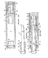
- the pipette illustrated in Figs. 3 and 4 includes a tubular body or handle 201 to which is threaded a body extender 208 that receives at one end an integral tip assembly including plunger tip 210 and capillary 211.
- a piston 224 at the end of plunger shaft 223 drives a collet rod 284 carrying at its opposite end a serrated collet 280 in opposition to a stiff collet closure spring 292 bearing on a shoulder of the collet rod and collet closure tube 275.
- a return spring 230 seated at one end upon a shoulder 231 formed in body extender 208 and seated at its other end on a shoulder 350 formed in collet closure tube 275 urges the plunger assembly to its fully retracted position shown.
- the collet closure spring 292 is stiffer than return spring 230 so it normally urges the collet closure 276 into engagement with the collet 280 to maintain it securely closed around the rod end 260 of the plunger tip 210 as the plunger assembly strokes in a pick-up and dispense mode.
- the adjusting lead screw 221 can be threaded in adjusting nut 220 by manual rotation of the hexagonal plunger shaft 223 within the hexagonal central plunger bore 222.
- the adjusted stroking volume is displayed on mechanical micrometer means 351 within the pipette body 201 which is operable directly by the adjusting screw.
- the illustrated capillary 211 has molded in one end annular retaining groove and rib 352 that seat upon corresponding annular retaining groove and rib 353 formed upon the end of body extender 208.
- the plunger tip 210 carries at one end a plunger head 262 that strokes within a precision molded portion 263 of the capillary 211 to pick up and dispense liquids as the plunger strokes.
- head 262 abuts shoulder 264 formed at the end of capillary 211.
- the head 262 has a necked-down end 354 which in that abutting position extends beyond the open end of capillary 211.
- the plunger stroke in liquid dispensing or pickup mode is controlled at one end by abutment of the plunger piston 224 with the end of lead screw 221 and at the other end by abutment of collet closure 276 with the shoulder 231 in body extender 208 upon which the return spring 230 also bears. Further depression of the plunger shaft 223 by the operator then compresses the stiffer collet closure spring 292 and moves the collet 280 away from the stopped collet closure 276. This permits the collet to open as shown in hidden lines in Fig.
- Plunger tip pick-up is accomplished by assembling the capillary 211 to the body extender 208 with the collet open in the tip ejection mode shown in Fig. 4. This pushes a plunger tip flange 355 into engagement with the end of collet 280 in opposition to the direct pressure exerted by the operator's thumb on plunger button 225. Release of that pressure then closes the collet as it returns under force exerted by collet closure spring 292 into collet closure 276 with the plunger tip flange 355 and collet 280 as shown in solid lines in Fig. 4.
- the plunger tip 210 moves the plunger head 262 from its abutment with capillary shoulder 264 until the collet becomes closed so that, when the collet closure 276 then retracts from shoulder 231 in the dispensing or liquid pick-up mode, the plunger tip head 262 may not be at a zero reference against capillary shoulder 264.
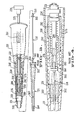
- Figs. 1 and 2 The embodiment of the invention illustrated in Figs. 1 and 2 includes a molded plastic handle or body 1 having an elongated barrel 2 with a central plunger cavity 3 and a lid portion 4 extending generally at right angles to the barrel portion 2 upon which mount an electronic display and various indicating means described hereinafter.
- a body cover 5 encloses the related display electronics and provides a comfortable gripping surface for the operator's fingers below the display mounted upon the body lid 4.
- An extender nut 6 threads upon mating threads 7 molded in the end of barrel portion 2 of the body 1 to secure to one end of the body a generally tubular body extender 8 which extends the central plunger cavity 3 of the body 1 as at 9 and carries at its free end the disposable, integral positive displacement type plunger tip 10 and capillary 11 assembly shown in Fig. 2.
- the end of the central plunger cavity 3 remote from body extender 8 has a threaded stroke adjusting nut 20 secured to the barrel portion 2 of the body 1.
- An adjusting screw 21 threads through the adjusting nut 20 and has a central circular bore 22 through which passes plunger shaft 23 carrying at one end piston 24 and at its other end a plunger button 25 for stroking manipulation by the thumb of the operator's hand.
- the plunger shaft 23 protrudes through a hole 26 in the end 27 of encoder carrier 28 within the central plunger cavity 3 of the body.
- the plunger shaft 23 is resiliently connected to encoder carrier 2P by means of conical thrust lock spring 29 bearing upon the plunger piston 24 and the end 27 of the encoder carrier 28.
- a knurled adjusting knob 35 having a smooth interior bore 36, which fits over the adjusting screw 21, threads the adjusting screw 21 through the fixed adjusting nut 20 by means of a pair of protruding ears 37 integral with the adjusting screw, each of which tracks in a separate longitudinal slot 38 formed along the adjusting knob interior bore 36.
- the adjusting screw is shown in its withdrawn position for maximum stroke length in ' Fig. 8 and in one extended position in Fig. 2.
- the adjusting screw 21 can be locked at any position such as the partially extended one of Fig. 2 by means of an adjusting lock ring 40, more clearly illustrated in Figs. 8 and 10.
- the adjusting lock ring 40 has a low cam portion 41, a high cam portion 42 and a ramp cam portion 43 which connects them.
- the high cam portion 42 moves a separate toothed lock segment 44 into engagement with mating teeth 45 carried along a circular annulus in one end of the knurled adjusting knob 35.
- the low cam portion 41 permits the teeth of segment 44 and 45 to disengage.
- the adjusting lock ring 40 is guided through a small arc of travel between one end of adjusting nut 20 and an abutment 46 on knurled adjusting knob 35.
- a retainer segment 47 retains the lock segment 44 in position over the lock ring ramp portion 43 and the low and high cam portions 41,42 adjacent to it.
- the operator by depressing plunger button 25 with a manipulating thumb may stroke the plunger assembly from the position shown in Fig. 2 or Fig. 8 that is adjustably set by stroke adjusting screw 21 to the other stroke end which is fixed and established by an abutment 50 on the encoder carrier 28 which at the end of that dispensing stroke abuts a first stop 51 on the body barrel portion 2.
- the length of the stroke can be adjusted by releasing the adjusting lock ring 40 and turning the knurled adjustableting knob 35 to advance or retract the adjusting screw 21 through adjusting nut 20.
- the plunger shaft 23 may over-travel further forward through the hole 26 in the encoder carrier end 27 if the eject lock shown in Figs. 8 and 9 is not in place.
- the eject lock prevents plunger shaft over-travel. It includes an eject lock housing 52 having a central bore 53 of a diameter sufficient to permit passage of plunger shaft 23 but not sufficient to permit passage of the larger diameter cylindrical end 54 of plunger button 25.
- the eject lock is set by a shiftable eject lock plate 55 to prevent over-travel of the plunger shaft 23 more than slightly beyond the end of the dispense stroke with abutment 50 and stop 51 engaged.
- the eject lock plate has an eccentric hole 56 which in the position shown in Fig. 9 is not axially aligned with and does not permit passage of the cylindrical end 54 of the plunger button 25. This restrains motion of the plunger shaft 23 to that which is slightly beyond the stroke end determined by encoder carrier abutment 50 and body stop 51.
- protrusion 57 on the eject lock plate 55 moves from the lock detent 58 as shown in Fig. 9 to unlock detent 59 to hold the plate unlocked.
- the eccentric hole 5 6 in the eject lock plate 55 is concentric with the plunger axis and its larger diameter permits passage of the smaller cylindrical end 54 of the plunger button. This enables over-travel of the plunger shaft 23 in a second mode for capillary and plunger tip attachment or ejection.
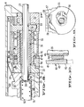
- Figs. 5, 6 and 7 illustrate the attachment and eject mode for the positive displacement plunger tip and capillary assembly shown in Figs. 1 and 2.
- the plunger tip 10 includes an elongated rod portion 60 having a chamfered end 61 and the other end formed with a plunger tip head 62 that fits tightly within the precision molded bore 63 of the capillary 11.
- the end of the capillary 11 adjacent to the precision molded bore 63 has an interior peripheral shoulder 64 against which the plunger tip head 62 abuts in its fully extended position with the plunger tip head 62, the extremity of which extends slightly beyond the end of capillary 11.
- the length of bore 63 of the capillary is at least commensurate with the plunger stroke.
- the capillary Adjacent to the precision molded bore 63 the capillary has a generally tapering bore 65 enlarging to the connecting end of the capillary which carries a flange 66 that fits within the open end of extender body 8.
- a canted annular spring 67 mounted in an annular groove 6 8 formed in the end of the extender body 8 holds the capillary at shoulder 69 with the beveled face 70 of flange 66 seated tightly against the corresponding beveled seat 71 formed in the extender body end.
- the plunger tip 10 and capillary 11 are an integral disposable assembly. A set of them may be dimensioned so as to provide a wide range of pipetting capacities.
- the I. embodiment shown is a 250 microliter assembly plunger tip made from polyethylene, polypropylene, polymethylpentane or similar inert and semi-rigid with the rod portion 60 .125 inches in diameter and the head 62 having its largest diameter at .1408 ⁇ .0005 inches to fit within a capillary having its precision molded bore 63 at .1393 ⁇ .0004 inches in diameter.
- the interior angle of the peripheral shoulder 64 of the capillary is at 30° and mates with an identical 30° chamfer on the plunger tip head 62.
- the chamfer 61 enables the plunger tip 10 to be inserted easily into the collet closure assembly shown in Figs. 2, 5 and 7.
- Other dimensional relationships between capillary bore 36 and plunger tip head 62 are employed for others of a set of tip assemblies to a range of pipetting capacities.
- the capillary 11 is of enlarged diameter at a "parking place" 120 slightly in excess of the diameter of the head 62 of the plunger tip adjacent to the precision molded bore 63 remote from interior peripheral shoulder 64.
- the plunger tip head 62 is not under compression as it would be within the precision molded bore 63 that has a smaller diameter than the head 62. Storage in the parking place prevents the plunger tip head 62 from cold forming to a smaller diameter that otherwise would affect the tight fit required as the head strokes within the precision molded bore 63 of the capillary. Also, as shown more particularly in Figs.
- the outer periphery of the capillary has a rack mounting step 121 for abutment with a rack 125 perforated as at 126 within which the capillary and plunger tip assemblies can be mounted with the plunger rod 60 protruding upwardly for stab type attachment to the pipette body of a new capillary and plunger tip assembly as hereinafter described.
- the collet closure means includes a collet closure tube 75 which at one closed end abuts piston 24 of the plunger shaft 23 and at its other end carries a collet closure 76.
- the collet closure 76 has a neck 77 that in the capillary eject mode moves into the throat 78 at the end of body extender 8 by over-travel of the plunger shaft to extend the collet closure tube 75 into the position shown in Fig. 7.
- the neck 77 of the collet closure 76 passing through throat 78 abuts capillary 11 and forces it off the extender body despite the retention force provided by canted spring 67. In this eject position of Fig.
- Collet seat 81 is spring biased by a light force spring 82 bearing against collet seat 81 and the threaded end 83 of collet rod 84 to which the collet 80, itself, threads.
- the light force collet spring 82 through collet seat 81 pushes the plunger tip 10 to the end of the mounted capillary 11 with plunger tip head 62 in engagement with capillary interior peripheral shoulder 64 and slightly beyond the end of the capillary.
- Collet shoulder 85 retains the spring biased collet seat 81 in the unloaded condition of Fig. 5.
- Collet rod 84 by means of collet pin 90 is pinned to encoder carrier 28 in a bayonet type thrust lock slot 28a with the pin 90 passing through a pair of diametrically opposed elongated slots 91 formed in collet closure tube 75 as shown in more detail in Fig. 11.
- Thrust lock spring 29 holds the assembly together.
- the collet rod 84 is normally urged by collet closure spring 92 into the collet closed position shown in Figs. 2 and 5.
- the collet closure spring 92 bears at one end against the closed end of the collet closure tube 75 and at the other end against the collet closure rod 84 urging the conical collet surface 93 into resilient engagement with the similarly conical closure surface 79 of collet closure 76.
- Collet closure spring 92 is stiff in comparison with return spring 30, so that during the calibration or pick-up and dispensing mode, spring 92 forces the collet closure and collet surfaces 79,93 firmly together.
- the plunger assembly strokes between adjusting screw 21 at one end and engagement between encoder abutment 50 and first stop 51 at the other. This engagement prevents further compression of return spring 30 and enables compression of the stiffer collet closure spring 82.
- the operator can then extend the plunger to over-travel against the collet closure spring 82 and move the collet closure 76 from the position shown in Fig. 5 to that in Fig. 7 and thereby eject an attached plunger tip and capillary assembly or enable pick up of a new one.
- the capillary 11 and plunger tip 10 assemblies may be rack mounted vertically on a laboratory bench or other support with the plunger rod 60 protruding upwardly. Attachment of a new capillary and plunger tip assembly then is easily done simply by pushing the pipette body 1 down with the plunger shaft 23 and collet closure 76 in the over-travel position of Fig. 7. This engages the beveled flange face 70 of the capillary 11 against beveled seat 71 in the body extender 8. The capillary flange 66 is held in seated relationship by canted spring 67 bearing against capillary shoulder 69. Release of the plunger shaft then closes the collet 80 around the rod portion 60 of the plunger tip 10.
- the collet gripping position on the rod portion 60 is not critical because the plunger tip head 62 has already been and remains seated at a zero volumetric reference against capillary shoulder 64 by means of the bias of collet spring 82 against collet seat 81. The plunger tip does not move during collet closure. Then, further release of the plunger shaft 23 moves the stroking mechanism through the zero volumetric reference at the first stop 51 with the plunger tip and capillary in synchronism at their zero reference, too.
- the electronic aspects of the described embodiment acquire, process and display data related to the volume of liquid being transferred by the pipette.
- Volume is derived from a linear incremental position sensing means for the plunger assembly. It comprises a potentiometer 99 having a linear resistive element 100 distributed within the pipette body barrel 2 along the plunger assembly stroke within the central plunger cavity 3. Potentiometer wiper 101 carried by the encoder carrier 28 is biased against the resistive element 100 to derive a voltage which is proportional to linear displacement of the plunger assembly with respect to the zero volumetric reference with carrier abutment 50 engaged with the first stop 51. That mechanical engagement is detected by zero volume switch 102 which closes when engagement occurs.
- Battery 103 powers the related electronics on circuit boards 104,105 mounted within body cover 105.
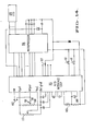
- FIG. 11 illustrates schematically one ; version of electronics mounted on boards 104,105 to operate a liquid crystal display 106 on body lid 4.
- the liquid crystal continuously displays the instantaneous volumetric content of the pipette up to the volume set by adjusting screw 21.
- Slide switch 107 also on the body lid 4 selects the volume range for a particular one of a set of four capillary-plunger tip assemblies used in the described embodiment.
- the illustrated electronics also may provide a timer function as at 108 or in another mode displayed on the liquid crystal 106.
- An alarm function on the body lid may be provided by piezoelectric beeper 109.
- the body lid 4 also mounts appropriate on-off push button 110 and mode select push button 111.
- the electronics illustrated in Fig. 11 include a CMOS gate array device 115 which provides an interface between microprocessor 116 and the linear potentiometer 99.
- the gate array device 115 converts the analog voltage developed by potentiometer 99 which is proportional to the stroking distance of travel of the plunger assembly from abutment at the first stop 51 to digital values supplied to the microprocessor.
- the gate array device 115 includes a dual slope analog to digital converter which operates in a ratiometric mode to provide a latched digital output which is indicative of the analog voltage supplied by the linear potentiometer 99.
- a trimmer potentiometer 117 adjusts the wiper-displacement/converter-count ratio by adjusting the converter full-scale reference voltage.
- liquid crystal 106 displays the increasing pipette volume as the finger button 25 is released from the zero reference at first stop 51 to the upper I stroking limit set by adjusting screw 21 where the display reads the pipette volume setting. As the finger button then is depressed, the display reads the decreasing pipette volume of liquid contained in the pipette until the zero volume position again is reached at first stop 51. There the zero volume switch 102 resets the display 106 to zero.
- timer In a "timer" mode, the operator may set the selected time interval shown on timer 108 which is continuously counted down in the display 106 by microprocessor 116 until an audible signal may be activated such as piezoelectric beeper 107.
- the display resets to the original interval to begin another cycle.
Landscapes
- Physics & Mathematics (AREA)
- Fluid Mechanics (AREA)
- General Physics & Mathematics (AREA)
- Health & Medical Sciences (AREA)
- Clinical Laboratory Science (AREA)
- Chemical & Material Sciences (AREA)
- Chemical Kinetics & Catalysis (AREA)
- Devices For Use In Laboratory Experiments (AREA)
- Sampling And Sample Adjustment (AREA)
Applications Claiming Priority (2)
| Application Number | Priority Date | Filing Date | Title |
|---|---|---|---|
| US06/588,921 US4567780A (en) | 1984-03-12 | 1984-03-12 | Hand-held pipette with disposable capillary |
| US588921 | 1984-03-12 |
Publications (2)
| Publication Number | Publication Date |
|---|---|
| EP0155087A2 true EP0155087A2 (de) | 1985-09-18 |
| EP0155087A3 EP0155087A3 (de) | 1988-06-15 |
Family
ID=24355867
Family Applications (1)
| Application Number | Title | Priority Date | Filing Date |
|---|---|---|---|
| EP85300987A Withdrawn EP0155087A3 (de) | 1984-03-12 | 1985-02-14 | Handgehaltene Pipette mit wegwerfbarem Kapillar |
Country Status (4)
| Country | Link |
|---|---|
| US (1) | US4567780A (de) |
| EP (1) | EP0155087A3 (de) |
| JP (1) | JPS60253843A (de) |
| AU (1) | AU3894685A (de) |
Cited By (21)
| Publication number | Priority date | Publication date | Assignee | Title |
|---|---|---|---|---|
| DE3614085A1 (de) * | 1985-12-12 | 1987-06-19 | Hirschmann Glasgeraete | Pipette |
| EP0250095A3 (en) * | 1986-06-18 | 1988-08-10 | Jencons (Scientific) Limited | Improvements in or relating to liquid dispensers |
| EP0421785A3 (en) * | 1989-10-04 | 1991-06-26 | Drummond Scientific Company | Pipetter device |
| EP0494735A3 (en) * | 1991-01-07 | 1992-12-09 | Labsystems Oy | Positive-displacement pipette |
| GB2327628A (en) * | 1997-07-26 | 1999-02-03 | Peerless Systems Limited | Powder pipette with replaceable tip |
| US6324925B1 (en) | 1998-06-10 | 2001-12-04 | Biohit Oyj | Suction device with means for removing a replaceable tip |
| DE10244960A1 (de) * | 2002-09-26 | 2004-04-08 | Siemens Ag | Kartusche mit Verbindung für einen Pump-Antrieb und Handhabungs-System |
| US8117928B2 (en) | 2006-04-25 | 2012-02-21 | Biohit Oyj | Method for selecting a pipette tip and a device for implementation |
| WO2012165982A1 (en) * | 2011-05-31 | 2012-12-06 | Pz Htl Spolka Akcyjna | Pipette for use with a pipette tip |
| US8376686B2 (en) | 2007-03-23 | 2013-02-19 | Flodesign Wind Turbine Corp. | Water turbines with mixers and ejectors |
| EP2659978A1 (de) * | 2012-05-02 | 2013-11-06 | Eppendorf AG | Pipette mit Verriegelungssystem |
| US9295986B2 (en) | 2012-05-02 | 2016-03-29 | Eppendorf Ag | Pipette with releasable locking of rotational position of actuating element |
| CN106459865A (zh) * | 2014-06-17 | 2017-02-22 | 雅马哈发动机株式会社 | 缸型尖头安装头、使用该缸型尖头安装头的头装置以及移动装置 |
| CN111408421A (zh) * | 2019-01-07 | 2020-07-14 | 苏州赛尼特格尔实验室科技有限公司 | 一种电子移液器的显示方法 |
| WO2021081530A1 (en) * | 2019-10-25 | 2021-04-29 | Mettler-Toledo Rainin, LLC | Powered positive displacement pipette syringe piston grasping mechanism |
| US11369954B2 (en) | 2019-10-25 | 2022-06-28 | Mettler-Toledo Rainin, LLC | Powered positive displacement pipette assembly |
| US11389792B2 (en) | 2019-10-25 | 2022-07-19 | Mettler-Toledo Rainin, LLC | Syringe for powered positive displacement pipette |
| US11471878B2 (en) | 2019-10-25 | 2022-10-18 | Mettler-Toledo Rainin, LLC | Powered positive displacement pipette |
| WO2023179776A1 (en) * | 2022-03-24 | 2023-09-28 | Mettler-Toledo (Changzhou) Measurement Technology Ltd. | Automatic piston-gripping apparatus and pipette comprising the same |
| US11911767B2 (en) | 2019-10-25 | 2024-02-27 | Mettler-Toledo Rainin, LLC | Positive displacement pipette syringe identification system |
| US12472491B2 (en) | 2022-06-28 | 2025-11-18 | Mettler-Toledo Rainin, LLC | Positive displacement pipette syringe with reduced fluid drag |
Families Citing this family (73)
| Publication number | Priority date | Publication date | Assignee | Title |
|---|---|---|---|---|
| US4616514A (en) * | 1983-06-06 | 1986-10-14 | Rainin Instrument Co., Inc. | Replaceable tip assembly for pipette |
| US4671123A (en) * | 1984-02-16 | 1987-06-09 | Rainin Instrument Co., Inc. | Methods and apparatus for pipetting and/or titrating liquids using a hand held self-contained automated pipette |
| FI852704L (fi) * | 1985-07-08 | 1987-01-09 | Labsystems Oy | Eldriven pipett. |
| CH671526A5 (de) * | 1985-12-17 | 1989-09-15 | Hamilton Bonaduz Ag | |
| JPS62184361A (ja) * | 1986-02-10 | 1987-08-12 | Nitsuteku:Kk | ピペツト装置 |
| US4896270A (en) * | 1986-03-21 | 1990-01-23 | Matrix Technologies Corporation | Computer controlled pipetting system |
| WO1989009555A1 (en) * | 1988-04-11 | 1989-10-19 | Heinz Industries, Inc. | Cosmetic tester |
| DE3875117D1 (de) * | 1988-10-21 | 1992-11-05 | Eppendorf Geraetebau Netheler | Pipettiervorrichtung. |
| FI87740C (fi) * | 1990-05-04 | 1994-04-08 | Biohit Oy | Pipett |
| US5111703A (en) * | 1990-09-10 | 1992-05-12 | Eastman Kodak Company | Liquid aspirating pipette and dispensing system |
| FI921647A0 (fi) * | 1992-04-13 | 1992-04-13 | Labsystems Oy | Spetsdelpipett. |
| GB9208386D0 (en) * | 1992-04-16 | 1992-06-03 | Amersham Int Plc | Storage and dispensing device for liquids |
| DE69429136D1 (de) * | 1993-06-30 | 2002-01-03 | Hamilton Co | Manuelle Abgabehilfe für eine Injektionsspritze |
| USD370974S (en) | 1995-01-27 | 1996-06-18 | Hamilton Company | Manual dispensing aid for a syringe |
| US5726363A (en) * | 1995-11-02 | 1998-03-10 | Kalidindi; Sanyasi R. | Liquid sampler |
| US6170343B1 (en) | 1996-09-09 | 2001-01-09 | Tyco Group S.A.R.L. | Electronically monitored mechanical pipette |
| AU733643B2 (en) * | 1996-09-09 | 2001-05-17 | Tyco Group S.A.R.L. | Electronically monitored mechanical pipette |
| US5998218A (en) * | 1996-09-09 | 1999-12-07 | Sherwood Services Ag | Calibration system for an electronically monitored mechanical pipette |
| US6019004A (en) * | 1996-09-10 | 2000-02-01 | Sherwood Services, Ag | Detachable pipette barrel |
| US5983733A (en) * | 1996-11-15 | 1999-11-16 | Hamilton Company | Manual pipette |
| US6066297A (en) * | 1997-01-03 | 2000-05-23 | Matrix Technologies Corporation | Small sample volume displacement pipette tips |
| US5892161A (en) * | 1997-09-09 | 1999-04-06 | Tyco Group S.A.R.L. | Transducer assembly for an electronically monitored mechanical pipette |
| USD426642S (en) * | 1999-03-05 | 2000-06-13 | Rainin Instrument Co., Inc. | Electronic pipette |
| WO2000051738A1 (en) * | 1999-03-05 | 2000-09-08 | Rainin Instrument Co., Inc. | Improved battery powered microprocessor controlled hand portable electronic pipette |
| US6299841B1 (en) * | 1999-03-05 | 2001-10-09 | Rainin Instrument Co., Inc. | Bilaterally symmetrical battery powered microprocessor controlled lightweight hand-holdable electronic pipette |
| US6254832B1 (en) * | 1999-03-05 | 2001-07-03 | Rainin Instrument Co., Inc. | Battery powered microprocessor controlled hand portable electronic pipette |
| US6524531B1 (en) * | 1999-09-14 | 2003-02-25 | Pharmacopeia, Inc. | Hand-held dispenser/aspirator |
| DE19963141A1 (de) * | 1999-12-24 | 2001-07-12 | Brand Gmbh & Co Kg | Pipette für ein Pipettiersystem |
| US6428750B1 (en) * | 2000-02-17 | 2002-08-06 | Rainin Instrument, Llc | Volume adjustable manual pipette with quick set volume adjustment |
| FR2807558B1 (fr) * | 2000-04-07 | 2004-04-02 | Gilson Sa | Pipette de prelevement munie de moyens d'affichage d'un parametre de la pipette |
| US6749812B2 (en) * | 2000-06-26 | 2004-06-15 | Vistalab Technologies | Automatic pipette detipping |
| FI20002241A0 (fi) * | 2000-10-11 | 2000-10-11 | Labsystems Oy | Säädettävä pipetti |
| US6973845B2 (en) | 2001-01-18 | 2005-12-13 | Beckman Coulter, Inc. | Low insertion force tip/mandrel |
| JP4148894B2 (ja) * | 2001-10-16 | 2008-09-10 | マトリックス・テクノロジイズ・コーポレーション | 手持ち式ピペット |
| AU2003251996A1 (en) * | 2002-07-23 | 2004-02-09 | Protedyne Corporation | Liquid handling tool having hollow plunger |
| EP1531935A1 (de) * | 2002-08-27 | 2005-05-25 | PZ HTL Spolka Akcyjna | Verfahren zum eichen einer pipette |
| US20060027033A1 (en) * | 2002-10-16 | 2006-02-09 | Richard Cote | Hand-held pipette employing voice recognition control |
| US7284454B2 (en) * | 2004-05-27 | 2007-10-23 | Matrix Technologies Corporation | Hand held pipette |
| US7396512B2 (en) * | 2003-11-04 | 2008-07-08 | Drummond Scientific Company | Automatic precision non-contact open-loop fluid dispensing |
| US7976793B2 (en) * | 2003-11-27 | 2011-07-12 | Gilson S.A.S. | Electronic pipette |
| DE102004003433B4 (de) * | 2004-01-21 | 2006-03-23 | Eppendorf Ag | Pipettiervorrichtung mit einer Abwurfeinrichtung für Pipettenspitzen |
| US7641859B2 (en) * | 2004-02-11 | 2010-01-05 | Matrix Technologies Corporation | Pipette tip mounting and ejection assembly and associated pipette tip |
| US20050184516A1 (en) * | 2004-02-23 | 2005-08-25 | Daniel Seguin | Pipette stabilizer |
| USD595419S1 (en) | 2004-09-07 | 2009-06-30 | Gilson S.A.S. | Pipette |
| USD561346S1 (en) * | 2004-09-07 | 2008-02-05 | Gilson S.A.S. | Pipette |
| RU2282581C2 (ru) * | 2004-11-29 | 2006-08-27 | Федеральное государственное унитарное предприятие "Государственный научный центр Российской Федерации Институт теоретической и экспериментальной физики им. А.И. Алиханова" | Способ изготовления калиброванного нанокапилляра и устройство для его изготовления |
| WO2006111977A2 (en) * | 2005-04-20 | 2006-10-26 | Shmuel Bukshpan | Automatic recording volume measurement apparatus |
| DE102005033378B4 (de) * | 2005-07-16 | 2012-05-31 | Eppendorf Ag | Kolbenhubpipette |
| USD548358S1 (en) * | 2006-03-01 | 2007-08-07 | Eppendorf Ag | Pipette |
| US9526515B2 (en) * | 2006-04-11 | 2016-12-27 | Koninklijke Philips N.V. | Device for positioning an ultrasound transducer inside a MR scanner |
| US7770475B2 (en) * | 2007-06-29 | 2010-08-10 | Rainin Instrument, Llc | Hybrid manual-electronic pipette |
| DE102007042555A1 (de) * | 2007-09-07 | 2009-04-02 | Eppendorf Ag | Pipette mit Kolben-Positionsanzeige |
| US7540205B2 (en) | 2007-09-17 | 2009-06-02 | Viaflo Corp. | Electronic pipettor |
| USD596754S1 (en) * | 2007-09-17 | 2009-07-21 | Viaflo Corporation | Pipette |
| US8033188B2 (en) | 2007-09-17 | 2011-10-11 | Integra Biosciences Corp. | Pipettor software interface |
| DE102008048620B4 (de) * | 2008-09-23 | 2011-09-15 | Ahn Biotechnologie Gmbh | Elektronische Kolbenhubpipette |
| USD596756S1 (en) * | 2008-10-29 | 2009-07-21 | E.I. Spectra, Llc | Pipette |
| EP2671054A1 (de) * | 2011-01-31 | 2013-12-11 | Witeg Labortechnik GmbH | Flaschendispenser mit digitaler volumenanzeige |
| DE102011109992A1 (de) * | 2011-08-11 | 2013-02-14 | Eppendorf Ag | Leiterplattenkabelvorrichtung für ein Laborprobengerät und Laborprobengerät |
| FR2980123B1 (fr) * | 2011-09-19 | 2013-10-11 | Gilson Sas | Pipette a deplacement positif presentant une fonction d'ejection amelioree |
| US20150013476A1 (en) | 2012-02-13 | 2015-01-15 | Thermo Fisher Scientific Oy | Electronic Pipette |
| FR2986718B1 (fr) | 2012-02-13 | 2014-03-28 | Gilson Sas | Pipette de prelevement permettant de detecter, de maniere simplifiee, le passage du piston par une position predeterminee |
| US20140002642A1 (en) | 2012-06-15 | 2014-01-02 | Elmar SWIEGOT | Absolute position detection |
| GB2504333B (en) * | 2012-07-26 | 2016-10-05 | Ttp Labtech Ltd | Liquid dispensing device |
| FR3003643B1 (fr) | 2013-03-25 | 2015-04-17 | Gilson Sas | Systeme de pipetage a deplacement positif presentant une fonction d'ejection amelioree |
| FR3010518A1 (fr) * | 2013-09-12 | 2015-03-13 | Gilson Sas | Pipette de prelevement presentant un dispositif ameliore de reglage et d'affichage d'un volume a prelever |
| FR3012883B1 (fr) * | 2013-11-07 | 2015-12-25 | Gilson Sas | Systeme de pipetage a deplacement positif, presentant une conception facilitant la prehension du piston de l'ensemble capillaire-piston |
| USD770056S1 (en) | 2014-12-15 | 2016-10-25 | Integra Biosciences Ag | Manual pipette |
| EP3335795B1 (de) * | 2016-12-16 | 2019-03-27 | Eppendorf AG | Verfahren zum dosieren von flüssigkeit mittels einer pipette und einer spritze und pipette zum betätigen einer spritze zum dosieren von flüssigkeit |
| DE202017101008U1 (de) * | 2017-02-23 | 2018-05-24 | Brand Gmbh + Co Kg | Dispenser und System zum Aufnehmen und Abgeben von Fluidvolumina |
| WO2018158690A1 (en) * | 2017-02-28 | 2018-09-07 | Waters Technologies Corporation | Devices and methods for analyzing intact proteins, antibodies, antibody subunits, and antibody drug conjugates |
| US10744498B2 (en) * | 2017-09-19 | 2020-08-18 | Mettler-Toledo Rainin, LLC | Pipette quickset volume adjustment mechanism |
| CN108562345B (zh) * | 2018-04-11 | 2024-01-30 | 佛山科学技术学院 | 一种精确测量微量液体的装置 |
Family Cites Families (18)
| Publication number | Priority date | Publication date | Assignee | Title |
|---|---|---|---|---|
| US3757585A (en) * | 1968-08-16 | 1973-09-11 | Heller Labor | Pipette apparatus |
| US3827305A (en) * | 1972-10-24 | 1974-08-06 | R Gilson | Adjustable pipette |
| DE2319175A1 (de) * | 1973-04-16 | 1974-10-31 | Oxford Lab | Detail-kolbenpipette |
| DE2541642C3 (de) * | 1975-09-18 | 1979-07-26 | Labora Mannheim Gmbh Fuer Labortechnik, 6800 Mannheim | Pipertier-Handpipette |
| US4054062A (en) * | 1976-05-03 | 1977-10-18 | Oxford Laboratories Inc. | Hand-held micropipettor with improved accuracy of liquid volumes transferred |
| US4086062A (en) * | 1977-02-23 | 1978-04-25 | Hach Chemical Company | Digital titration device |
| FR2389104A1 (fr) * | 1977-04-27 | 1978-11-24 | Marteau D Autry Eric | Pipette reglable de distribution d'echantillons liquides |
| US4096751A (en) * | 1977-06-15 | 1978-06-27 | Oxford Laboratories Inc. | Hand-held micropipettor with fluid transfer volume adjustment mechanism |
| US4096750A (en) * | 1977-06-15 | 1978-06-27 | Oxford Laboratories Inc. | Hand-held micropipettor with fluid transfer volume adjustment mechanism |
| SU691752A1 (ru) * | 1977-09-14 | 1979-10-15 | Киевский технологический институт легкой промышленности | Электронна микробюретка |
| FR2473124A1 (fr) * | 1980-01-04 | 1981-07-10 | Marteau D Autry Eric | Dispositif de prelevement et de distribution de volumes reglables de liquides, a affichage numerique |
| US4489618A (en) * | 1980-07-03 | 1984-12-25 | Meyer Richard C | Pipet signalling system |
| US4435989A (en) * | 1980-07-03 | 1984-03-13 | Beckman Instruments, Inc. | Plunger operated pipet |
| JPS5919736B2 (ja) * | 1981-02-09 | 1984-05-08 | 株式会社ニチリヨ− | ピペット装置 |
| US4395921A (en) * | 1981-06-26 | 1983-08-02 | Scientific Manufacturing Industries, Inc. | Adjustable volume liquid dispenser |
| DE3204178C2 (de) * | 1982-02-06 | 1986-03-20 | Eppendorf Gerätebau Netheler + Hinz GmbH, 2000 Hamburg | Pipettiervorrichtung |
| US4442722A (en) * | 1982-02-23 | 1984-04-17 | Beckman Instruments Inc. | Plunger operated pipet |
| US4487081A (en) * | 1982-08-27 | 1984-12-11 | Donald H. De Vaughn | Pipetting techniques using replaceable tips |
-
1984
- 1984-03-12 US US06/588,921 patent/US4567780A/en not_active Expired - Fee Related
-
1985
- 1985-02-14 EP EP85300987A patent/EP0155087A3/de not_active Withdrawn
- 1985-02-19 AU AU38946/85A patent/AU3894685A/en not_active Abandoned
- 1985-03-11 JP JP60048083A patent/JPS60253843A/ja active Pending
Cited By (34)
| Publication number | Priority date | Publication date | Assignee | Title |
|---|---|---|---|---|
| EP0232517A3 (en) * | 1985-12-12 | 1988-06-22 | Glasgeratebau Hirschmann | Pipette |
| DE3614085A1 (de) * | 1985-12-12 | 1987-06-19 | Hirschmann Glasgeraete | Pipette |
| EP0250095A3 (en) * | 1986-06-18 | 1988-08-10 | Jencons (Scientific) Limited | Improvements in or relating to liquid dispensers |
| EP0421785A3 (en) * | 1989-10-04 | 1991-06-26 | Drummond Scientific Company | Pipetter device |
| EP0494735A3 (en) * | 1991-01-07 | 1992-12-09 | Labsystems Oy | Positive-displacement pipette |
| GB2327628A (en) * | 1997-07-26 | 1999-02-03 | Peerless Systems Limited | Powder pipette with replaceable tip |
| US6324925B1 (en) | 1998-06-10 | 2001-12-04 | Biohit Oyj | Suction device with means for removing a replaceable tip |
| DE10244960A1 (de) * | 2002-09-26 | 2004-04-08 | Siemens Ag | Kartusche mit Verbindung für einen Pump-Antrieb und Handhabungs-System |
| DE10244960B4 (de) * | 2002-09-26 | 2004-12-02 | Siemens Ag | Kartusche mit Verbindung für einen Pump-Antrieb und Handhabungs-System für einen flüssigen oder gasförmigen Stoff |
| US7182228B2 (en) | 2002-09-26 | 2007-02-27 | Siemens Aktiengesellschaft | Cartridge with connection for a pump-drive and fluid handling system |
| US8117928B2 (en) | 2006-04-25 | 2012-02-21 | Biohit Oyj | Method for selecting a pipette tip and a device for implementation |
| US8376686B2 (en) | 2007-03-23 | 2013-02-19 | Flodesign Wind Turbine Corp. | Water turbines with mixers and ejectors |
| US9624025B2 (en) | 2011-05-31 | 2017-04-18 | Corning Incorporated | Pipette for use with a pipette tip |
| WO2012165982A1 (en) * | 2011-05-31 | 2012-12-06 | Pz Htl Spolka Akcyjna | Pipette for use with a pipette tip |
| EP2659978A1 (de) * | 2012-05-02 | 2013-11-06 | Eppendorf AG | Pipette mit Verriegelungssystem |
| US9295986B2 (en) | 2012-05-02 | 2016-03-29 | Eppendorf Ag | Pipette with releasable locking of rotational position of actuating element |
| CN106459865A (zh) * | 2014-06-17 | 2017-02-22 | 雅马哈发动机株式会社 | 缸型尖头安装头、使用该缸型尖头安装头的头装置以及移动装置 |
| EP3159395A4 (de) * | 2014-06-17 | 2017-07-19 | Yamaha Hatsudoki Kabushiki Kaisha | Zylinderspitzenmontagekopf und kopfvorrichtung sowie bewegungsvorrichtung damit |
| CN106967593A (zh) * | 2014-06-17 | 2017-07-21 | 雅马哈发动机株式会社 | 头装置以及具备该头装置的移动装置 |
| US9891143B2 (en) | 2014-06-17 | 2018-02-13 | Yamaha Hatsudoki Kabushiki Kaisha | Cylinder tip mounting head, and head device and movement device each using same |
| US9925535B2 (en) | 2014-06-17 | 2018-03-27 | Yamaha Hatsudoki Kabushiki Kaisha | Cylinder tip mounting head, and head device and movement device each using same |
| CN106459865B (zh) * | 2014-06-17 | 2019-01-08 | 雅马哈发动机株式会社 | 缸型尖头安装头、使用该缸型尖头安装头的头装置以及移动装置 |
| CN111408421A (zh) * | 2019-01-07 | 2020-07-14 | 苏州赛尼特格尔实验室科技有限公司 | 一种电子移液器的显示方法 |
| WO2021081530A1 (en) * | 2019-10-25 | 2021-04-29 | Mettler-Toledo Rainin, LLC | Powered positive displacement pipette syringe piston grasping mechanism |
| US11369954B2 (en) | 2019-10-25 | 2022-06-28 | Mettler-Toledo Rainin, LLC | Powered positive displacement pipette assembly |
| US11389792B2 (en) | 2019-10-25 | 2022-07-19 | Mettler-Toledo Rainin, LLC | Syringe for powered positive displacement pipette |
| US11446672B2 (en) | 2019-10-25 | 2022-09-20 | Mettler-Toledo Rainin, LLC | Powered positive displacement pipette syringe piston grasping mechanism |
| US11471878B2 (en) | 2019-10-25 | 2022-10-18 | Mettler-Toledo Rainin, LLC | Powered positive displacement pipette |
| US11850582B2 (en) | 2019-10-25 | 2023-12-26 | Mettler-Toledo Rainin, LLC | Powered positive displacement dispensing methods |
| US11911767B2 (en) | 2019-10-25 | 2024-02-27 | Mettler-Toledo Rainin, LLC | Positive displacement pipette syringe identification system |
| US12246315B2 (en) | 2019-10-25 | 2025-03-11 | Mettler-Toledo Rainin, LLC | Powered positive displacement pipette assembly |
| US12616974B2 (en) | 2019-10-25 | 2026-05-05 | Mettler-Toledo Rainin, LLC | Positive displacement pipette syringe identification system |
| WO2023179776A1 (en) * | 2022-03-24 | 2023-09-28 | Mettler-Toledo (Changzhou) Measurement Technology Ltd. | Automatic piston-gripping apparatus and pipette comprising the same |
| US12472491B2 (en) | 2022-06-28 | 2025-11-18 | Mettler-Toledo Rainin, LLC | Positive displacement pipette syringe with reduced fluid drag |
Also Published As
| Publication number | Publication date |
|---|---|
| US4567780A (en) | 1986-02-04 |
| JPS60253843A (ja) | 1985-12-14 |
| EP0155087A3 (de) | 1988-06-15 |
| AU3894685A (en) | 1985-09-19 |
Similar Documents
| Publication | Publication Date | Title |
|---|---|---|
| US4567780A (en) | Hand-held pipette with disposable capillary | |
| US3855867A (en) | Liquid transfer pipetting device | |
| US5611784A (en) | Manual dispensing aid for a syringe | |
| US3827305A (en) | Adjustable pipette | |
| US4096750A (en) | Hand-held micropipettor with fluid transfer volume adjustment mechanism | |
| US4096751A (en) | Hand-held micropipettor with fluid transfer volume adjustment mechanism | |
| US4744955A (en) | Adjustable volume pipette sampler | |
| US5104624A (en) | Pipetter | |
| US4023716A (en) | Micro-dispensing liquid pipet | |
| US4973318A (en) | Disposable syringe | |
| US4244366A (en) | Syringe stroke controlling mechanism | |
| US4824642A (en) | Multi-channel pipetter | |
| US4936833A (en) | Cartridge-holder assembly for medication dispensing unit | |
| US4086062A (en) | Digital titration device | |
| CA1081184A (en) | Jar mounted pipettor | |
| US5320810A (en) | Pipette with an axially stationary volume adjusting wheel | |
| US4672857A (en) | Liquid microdispenser | |
| IE43550B1 (en) | Measuring and pipetting device | |
| IL89189A (en) | A dosage unit designed to determine the dosage of a number of measured amounts of a liquid such as an insulin preparation from a filler | |
| US5998218A (en) | Calibration system for an electronically monitored mechanical pipette | |
| KR20020087411A (ko) | 복귀 스프링이 없는 인체공학적 수동 공기 변위 피펫 | |
| EP0496784B1 (de) | Pipette | |
| US7204163B2 (en) | Mechanical piston pipette | |
| US3749284A (en) | Syringe | |
| GB1597336A (en) | Micropipettors |
Legal Events
| Date | Code | Title | Description |
|---|---|---|---|
| PUAI | Public reference made under article 153(3) epc to a published international application that has entered the european phase |
Free format text: ORIGINAL CODE: 0009012 |
|
| AK | Designated contracting states |
Designated state(s): DE FR GB IT |
|
| RAP1 | Party data changed (applicant data changed or rights of an application transferred) |
Owner name: BAXTER TRAVENOL LABORATORIES, INC. |
|
| PUAL | Search report despatched |
Free format text: ORIGINAL CODE: 0009013 |
|
| AK | Designated contracting states |
Kind code of ref document: A3 Designated state(s): DE FR GB IT |
|
| STAA | Information on the status of an ep patent application or granted ep patent |
Free format text: STATUS: THE APPLICATION IS DEEMED TO BE WITHDRAWN |
|
| 18D | Application deemed to be withdrawn |
Effective date: 19880831 |
|
| RIN1 | Information on inventor provided before grant (corrected) |
Inventor name: KARNE, BENN Inventor name: SHACKELFORD, CARL L. Inventor name: KOBALL, BRUCE, R. Inventor name: OPPENLANDER, JON E. |