EP0154995A2 - Blutdruckmessgerät - Google Patents
Blutdruckmessgerät Download PDFInfo
- Publication number
- EP0154995A2 EP0154995A2 EP85102899A EP85102899A EP0154995A2 EP 0154995 A2 EP0154995 A2 EP 0154995A2 EP 85102899 A EP85102899 A EP 85102899A EP 85102899 A EP85102899 A EP 85102899A EP 0154995 A2 EP0154995 A2 EP 0154995A2
- Authority
- EP
- European Patent Office
- Prior art keywords
- pressure
- blood pressure
- cuff
- diastolic
- systolic
- Prior art date
- Legal status (The legal status is an assumption and is not a legal conclusion. Google has not performed a legal analysis and makes no representation as to the accuracy of the status listed.)
- Granted
Links
Images


Classifications
-
- A—HUMAN NECESSITIES
- A61—MEDICAL OR VETERINARY SCIENCE; HYGIENE
- A61B—DIAGNOSIS; SURGERY; IDENTIFICATION
- A61B5/00—Measuring for diagnostic purposes; Identification of persons
- A61B5/02—Detecting, measuring or recording pulse, heart rate, blood pressure or blood flow; Combined pulse/heart-rate/blood pressure determination; Evaluating a cardiovascular condition not otherwise provided for, e.g. using combinations of techniques provided for in this group with electrocardiography or electroauscultation; Heart catheters for measuring blood pressure
- A61B5/021—Measuring pressure in heart or blood vessels
- A61B5/022—Measuring pressure in heart or blood vessels by applying pressure to close blood vessels, e.g. against the skin; Ophthalmodynamometers
Definitions
- This invention relates to a device for measuring blood pressure and in particular to such a device which requires very a short time duration for measurement.
- a device for measuring blood pressure, making use of a pressure cuff is based on the processes of pressurizing a pressure cuff until the artery is completely closed, gradually evacuating the cuff (gradual evacuation) thereafter, and determining systolic pressure and /or diastolic pressure according to the detection of the Korotkoff sound (K sound) and its disappearance, or detecting pulsatile waves during the evacuation of the pressure cuff and obtaining the systolic pressure and /or the diastolic pressure from the point where rate of the increase and /or the decrease of the amplitude of the pulsatile wave increases and /or decreases, as the case may be.
- K sound Korotkoff sound
- the pressure cuff must be pressurized slightly over the systolic pressure (systolic pressure +0() and subsequently evacuated until the pressure cuff pressure drops slightly below the diastolic pressure (diastolic pressure - ⁇ ), and, therefore, the time duration required for measuring blood pressure was undesirably long.
- systolic pressure +0() the pressure cuff pressure
- diastolic pressure - ⁇ diastolic pressure
- a primary object of this invention is to provide a device for measuring blood pressure which requires a time duration for measurement which is substantially shorter than those required by conventional devices for measuring blood pressure.
- a second object of this invention is to provide a device for measuring blood pressure which is less painful to the patient than conventional ones.
- a third object of this invention is to provide a device for measuring blood pressure which is accurate in spite of its high speed of measurement.
- a device for measuring blood pressure comprises: a pressure cuff; a pressurizing means for pressurizing the pressure cuff; an evacuation means for gradually or quickly evacuating the pressure cuff; a pressure sensor for detecting the pressure of the pressure cuff; a pulsatile wave detecting means for detecting pulsatile signals contained the pressure of the pressure cuff; a blood pressure determining means for determining systolic blood pressure and mean blood pressure from the wave form information of the pulsatile wave obtained by the pulsatile wave detecting means as the pressure cuff is being gradually evacuated by the evacuating means; and a diastolic pressure determining means for computing diastolic blood pressure from the systolic blood pressure and the mean blood pressure determined by the blood pressure determining means.
- this device for measuring blood pressure because the diastolic blood pressure is computed from the systolic blood pressure and the mean blood pressure, quick evacuation of the pressure cuff is possible immediately after the mean blood pressure is determined by a gradual evacuation of of the pressure cuff, and, therefore, the time duration required by the conventional devices between the determination of the mean blood pressure and the diastolic blood pressure may be omitted, whereby a considerable saving in the time required for the measurement can be accomplished.
- a device for measuring blood pressure comprising, in place of the said blood pressure determining means, a blood pressure determining means for determining mean blood pressure and diastolic blood pressure from the wave form information of the pulsatile wave obtained by the pulsatile wave detecting means as the pressure cuff is being gradually evacuated by the evacuating means; and, in place of the diastolic blood pressure determining means for computing systolic blood pressure from the mean blood pressure and the diastolic blood pressure determined by the blood pressure determining means.
- the gradual evacuation may be started at a cuff pressure'which is slightly higher than a predicted mean blood pressure and, therefore, the time durations, that were conventionally required for the pressurization of the pressure cuff and the gradual evacuation thereof for the determination of the systolic pressure, may be omitted, whereby a considerable saving in the time required for the measurement can be accomplished.
- the time duration required for measurement is reduced and the time duration of applying pressure to an arm can be reduced, the pain to the patient can be reduced and an potential hazard to an emaciated or diathetic patients may be likewise diminished. Additionally, avoidance of any congestion of blood contributes to the elimination of measurement errors.
- the constant A may fluctuate from one person to another because of individual differences and fixing the constant A to a fixed value disregarding this fluctuation may lead to some measuring errors.
- this invention further provides a device for measuring blood pressure which is based on the steps of determining, in the first step, systolic blood pressure, mean blood pressure and diastolic blood pressure, computing a constant A from these blood pressure values, thereafter or in the second step, determining first the systolic blood pressure and the mean blood pressure or the mean blood pressure and the diastolic blood pressure according the the process of gradual evacuation of the pressure cuff, and then computing the remaining blood pressure value according to the constant A.
- the measurement time may be reduced. And because the time duration of applying pressure to an arm can be reduced, the pain to the patient can be reduced and measurement errors may be reduced because of the absence of congestion of blood. Additionally, because the constant A computed from the patient at the particular,time point is used for computing the remaining blood pressure value, fluctuations arising from individual difference and circumstantial difference may be compensated and a greater accuracy of measurement can be achieved.
- FIG. 1 is a block diagram of an electronic sphygmomanometer according to an embodiment of this invention.
- a pressurization pump 1 is communicated with an exhaust valve 3 and a pressure cuff 4 by way of an air conduit 2.
- the pressure cuff 4 is communicated with a pressure sensor 5 by way of another air conduit 2 so that the pressure in the pressure cuff 4 may be converted into an electric signal by the pressure sensor 5.
- An output end of the pressure sensor 5 is connected to an amplifier 6, whose output end is connected to an input end of an A/D converter 7 and also to another input end of the A/D converter 7 by way of a band pass filter 8.
- an amplifier 6 whose output end is connected to an input end of an A/D converter 7 and also to another input end of the A/D converter 7 by way of a band pass filter 8.
- one of the input ends of the A/D converter 7 is fed with a static pressure of the pressure cuff 4 from the amplifier 6 while the other of the input ends of the A/D converter 7 is fed with the pulsatile component of the pressure of the pressure cuff 4 from the band pass filter 8.
- An output end of the A/D converter 8 is connected to a CP U 9 so that digitalized data of the cuff pressure and the pulsatile signal may be supplied to the CPU 9.
- the CPU 9 which includes memory, such as RAM and ROM, therein, performs the functions of determining the systolic blood pressure and the means blood pressure and, based upon these blood pressure values, determining the diastolic blood pressure, according to a program stored in the ROM.
- the CPU 9 additionally has control functions of driving and stopping the pressurization pump 1 according to a signal a and of switching over the exhaust valve 3 between a gradual evacuation and quick evacuation according to a signal b.
- the systolic blood pressure, the mean blood pressure and the diastolic blood pressure, determined and computed by the CPU 9, are displayed by a display unit'6.
- this sphygmomanometer is based on the oscillation method, according to which blood pressures are determined by making use of the amplitude of the pulsatile wave which is part of the wave form information of the pulsatile wave, a number of algorithms are known for determining the blood pressures according to the oscillation method, and, for instance, systolic and/or diastolic pressure may be determined as the cuff pressure corresponding to a certain fraction of the maximum value of the amplitude this embodiment, the following algorithm is used for the determination of the blood pressures:
- the pressurizing pump 1 is driven by the signal a from the CPU 9 and the pressure cuff 4 is pressurized (step 1).
- the cuff pressure abruptly rises as shown by a to b in Figure 3 (A).
- step 2 it is determined as the cuff pressure is fed from the pressure sensor 5 into the CPU 9, whether the cuff pressure has reached a certain predetermined cuff pressure (which is generally higher than a predicted systolic blood pressure) or not (step 2). During the time the cuff pressure is lower than the predetermined value, the result of this determination is NO and the processing action remains at step 2. In the meantime, the pressurization by the pressurization pump 1 is continued.
- a certain predetermined cuff pressure which is generally higher than a predicted systolic blood pressure
- step 2 When the cuff pressure reaches the predetermined value, the result of the determination process in step 2 turns into YE S and the signal a is turned off, which terminates the driving of the pressurization pump 1 and the pressurization of the pressure cuff 4 (step 3?.. At the same time, a gradual evacuation from the exhaust valve 3 is started and the cuff pressure begins declining, crossing over point b in Figure 3 (A). The actual measurement is started at this time point. Specifically, it is determined whether the increasing rate of the amplitude of the pulsatile wave signal, fed from the band pass filter 8 into the CPU 9 by way of the A/D converter 7, is greater than a predetermined value or not, in step 5. If the amplitude of the pulsatile wave signal is substantially constant, the result of this determination is NO and the processing action remains at step 5. In the meantime, the cuff pressure gradually declines.
- step 5 When the increasing rate of the detected pulsatile wave signal exceeds the predetermined value (refer to point c' of Figure 3 (A)), the determination result of step 5 turns into YES and the action flow proceeds to step 6. And the cuff pressure (refer to the point c in Figure 3(A)) at this time point is determined as the systolic blood pressure. And this systolic blood pressure is stored in the memory of the CPU 9.
- step 7 it is determined whether the amplitude of the pulsatile wave signal has reached the maximum value or not. As long as the amplitude of the pulsatile wave signal is rising, the determination result is NO and the processing action remains at step 7. However, when the amplitude of the pulsatile wave signal has reached the maximum value (refer to point d' in Figure.3 (A)), the determination result turns into YES and the processing action proceeds to step 8. And the cuff pressure at this time point (refer to d in Figure 3 (A)) is determined as the mean blood pressure. And this mean blood pressure is likewise stored in the memory of the CPU 9.
- the diastolic blood pressure is computed from the systolic blood pressure and the mean blood pressure without waiting for the cuff pressure to be reduced to the level of a diastolic blood pressure (step 9).
- the computation of the diastolic blood pressure is performed according to the following formula:
- the systolic blood pressure and the mean blood pressure are determined and the diastolic blood pressure is computed, they are displayed on the display unit 10 (step 10).
- the CPU 9 sends the signal b to the exhaust valve 3 so as to rapidly evacuate the pressure cuff 4 (step 11).
- the rapid evacuation of the pressure cuff 4 takes place when the cuff pressure has dropped from the mean pressure by a value (refer to the point e in Figure 3 (A)).
- T a slight delay in the onset of the rapid evacuation of the pressure cuff 4.
- the total time duration required for measurement with the electronic sphygmomanometer of this embodiment corresponds to the duration from t, to t 4 as shown in Figure 3 (A).
- Figure 3 (B) is a time chart of a cuff pressure, a pulsatile signal and a measurement time according to a conventional electronic sphygmomanometer, and is given here for comparison with Figure 3 (A).
- the diastolic pressure is also determined from the amplitude of the pulsatile wave signal.
- the cuff pressure corresponding to the point f' at which the decreasing rate of the amplitude diminishes is determined as the diastolic blood pressure (refer for the point f in Figure 3 (A)). Therefore, the time required for measurement in this case is from t 1 to t 6- It can be readily seen by comparing the time durations required for measurement in Figure 3 (A) and 3 (B), the one given in Figure 3 (A) is shorter than the other.
- circuit structure of this embodiment is identical to the one shown in Figure 1 but the processing action in its CPU 9 proceeds in a different manner.
- the cuff pressure is decreased from a level which is higher than that of systolic blood pressure, and the amplitude of the pulsatile wave signal is detected. Based on the detected amplitude of the pulsatile wave signal, the systolic blood pressure and the mean blood pressure are determined, and the diastolic blood pressure is computed from the systolic blood pressure and the mean blood pressure thus determined, before the rapid evacuation of the pressure cuff takes place.
- the cuff pressure is selected at a level which is slightly higher than the mean blood pressure and the gradual evacuation of the pressure cuff is started from this point so that the mean pressure and then the diastolic blood pressure may be determined from the amplitude of the pulsatile wave signal and the systolic blood pressure may be computed. from the mean blood pressure and the diastolic blood pressure, before the rapid evacuation of the pressure cuff.
- the two embodiments are common in reducing the time duration required for measurement, but the second embodiment can reduce the time duration even more, according to its working principle, because the timc duration between the time t 3 of detecting the mean blood pressure and the time t 5 of detecting the diastolic blood pressure is normally shorter than the time duration between the time t 2 of detecting the systolic blood pressure and the time t 3 of detecting the mean blood pressure, as shown in Figure 3 (B).
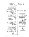
- FIG 4 is a control flow diagram of the second embodiment of the electronic sphygmomanometer of this invention.
- the processing action from step 21 to step 24 is substantially identical to that from step 1 to step 4 shown in Figure 2.
- the predetermined value in step 22 is selected so that (mean blood pressure) ⁇ (predetermined value) ⁇ (systolic blood pressure).
- step 24 When a gradual evacuation is started in step 24, first, the maximum amplitude of the pulsatile wave signal is determined (step 25) and, upon detection of the maximum value, the cuff pressure at the time is determined as the mean blood pressure (step 26). During the succeeding gradual evacuation of the cuff pressure, the point at which the decreasing rate of the amplitude of the pulsatile wave signal diminishes is determined (step 27) and this cuff pressure is determined as the diastolic blood pressure (step 28), Then, the systolic blood pressure is computed from the determined mean blood pressure and diastolic blood pressure (step 29).
- (systolic blood pressure) (mean blood pressure) + A (mean blood pressure - diastolic blood pressure). Then, in a similar way as that shown in Figure 2, the systolic blood pressure, the mean blood pressure and the diastolic blood pressure, thus determined and computed, are displayed on the display unit 10 (step 50), followed by rapid evacuation of the pressure cuff 4 (step 51).
- the pressurization and evacuation of the pressure cuff are automatically performed by the control from the CPU 9, this invention is not limited thereby, but may also be applied to the case of manual pressurization and manual evacuation of the pressure cuff. If manual evacuation is to be adopted, it is desirable to show, for instance by a buzzer, the beginning of a rapid evacuation.
- FIG. 5 is a block diagram of an electronic sphygmomanometer according to a third embodiment of this invention.
- the structure of this embodiment is very similar to the one shown in Figure 1, in connection with the first and the second embodiments, but a pair of digital switches 11 and 12 are connected to the CPU 9 and their functions will be described later.
- the CPU 9 further has a T1 timer and a T2 timer internally.
- the time durations to be set up in these timers are set up by digital switches 11 and 12. These time durations are selected so that T1 « T2.
- the electronic sphygmomanometer of this embodiment first determines systolic blood pressure, mean blood pressure and diastolic pressure through a series of cuff pressure variations of pressurization, gradual evacuation and rapid evacuation of the pressure cuff, and computes a the constant A from these blood pressure values (the constant A is computed at t1 in Figure 2).
- the processes of pressurization, gradual evacuation, rapid evacuation and intermission are repeated at an duration of T1, and the systolic pressure is computed from the determined mean blood pressure, diastolic blood pressure and constant A.
- the obtained blood pressure values are displayed on a display 10.
- this sphygmomanometer is based on the oscillation method, according to which blood pressures are determined by making use of the amplitude of the pulsatile wave which is part of the wave form information of the pulsatile wave, a number of algorithms are known for determining the blood pressures according to the oscillation method, but, in this embodiment, the following algorithm is used for the determination of the blood pressures:
- the T1 time is started (step 41), and the T2 time is simultaneously started (step 42).
- systolic blood pressure, mean blood pressure and diastolic blood pressure are determined (measured) and the constant A is computed (step 43).
- step 51 it is determined, for each sample time, as the cuff pressure is fed from the pressure sensor 5 into the CPU 9, whether the cuff pressure has reached a certain predetermined cuff pressure (which is generally higher than a predicted systolic blood pressure) or not (step 51). During the time the cuff pressure is lower than the predetermined value, the result of this determination is NO and the processing action remains at step 51. In the meantime, the pressurization by the pressurization pump 1 is continued.
- a certain predetermined cuff pressure which is generally higher than a predicted systolic blood pressure
- step 51 When the cuff pressure reaches the predetermined value, the result of the determination process in step 51 turns into YES and the signal a is turned off, which terminates the driving of the pressurization pump 1 and the pressurization of the pressure cuff 4 (step 52). At the same time, a gradual evacuation from the exhaust valve 3 is.started and the cuff pressure begins declining (step 53).
- step 54 it is determined whether the increase rate of the amplitude of the pulsatile wave signal supplied to the CPU 9 has exceeded a certain value or not (step 54). If the increase rate of the amplitude of the pulsatile wave is substantially constant, then the determination result is NO and the process action remains at this step. In the meantime, the cuff pressure gradually declines.
- step 54 When the increasing rate of the detected pulsatile wave signal exceeds the predetermined value, the determination result of step 54 turns into YES and the cuff pressure at this point is determined as systolic blood pressure. This systolic blood pressure is stored in the memory of the CPU 9 (step 55).
- step 56 it is determined whether the amplitude of the pulsatile wave signal has reached the maximum value or not. As long as the amplitude of the pulsatile wave signal is rising, the determination result is NO and the processing action remains at step 56. However, when the amplitude of the pulsatile wave signal has reached the maximum value, the determination result turns into YES and the cuff pressure at this time point is determined as mean blood pressure. And this mean blood pressure is likewise stored in the memory of the CPU 9 (step 57).
- the cuff pressure continues declining through gradual evacuation of the pressure cuff. And, the amplitude of the pulsatile wave signal likewise decreases. Then it is determined whether the decrease rate of the pulsatile wave signal is smaller that a certain predetermined value or not (step 58). If the amplitude of the pulsatile wave signal is declining, the determination result is NO and the process flow remains at step 58, but, if the amplitude of the pulsatile wave signal is constant or the decrease rate of the amplitude of the pulsatile wave signal has become less than the predetermined value, then the determination result is YES and the cuff pressure at this time point is determined as diastolic blood pressure (step 59). This diastolic blood pressure is also stored in the memory of the CPU 9.
- the systolic blood pressure, the mean blood pressure and the diastolic blood pressure are determined.
- the method of determining blood pressure was the same as that in a conventional electronic sphygmomanometer.
- step 44 of Figure 7 Upon completion of this process, the process flow escapes from step 44 of Figure 7 and moves over to step 45 for the determination whether t-he T2 timer is up or not.
- This determination result is initially NO and, after the process flow has advanced to step 45, it is determined whether the T1 time is up or not and this continues until the T1 timer times up. In the meanwhile, the measurement of blood pressure is suspended. In other words, an intermission of measurement takes place and continues until the next measurement is made.
- step 45 When the T1 timer times up, then the determination result in step 45 turns into YES, mean blood pressure and diastolic blood pressure are determined (measured) in step 46, and systolic blood pressure is determined from these mean blood pressure and diastolic blood pressure and the already computed constant A.
- the pressure cuff 4 is pressurized (step 70), it is determined whether the cuff pressure has reached a predetermined value (step 71) and, when it has reached the predetermined value, the pressurization is terminated (step 72) and gradual evacuation of the pressure cuff 4 begins (step 73).
- the process flow so far is similar to steps 50 to 53 of the routine shown in Figure 8. But a difference exists in that the predetermined value of step 71 is set up at a value which is slightly greater than the mean blood pressure.
- step 73 When a gradual evacuation is started in step 73, first, the maximum amplitude of the pulsatile wave signal is determined (step 74) and, upon detection pf the maximum value, the cuff pressure at the time is determined as the mean blood pressure (step 75). During the succeeding gradual evacuation of the cuff pressure, the point at which the decreasing rate of the amplitude of the pulsatile wave signal diminishes is determined (step 76) and this cuff pressure is determined as the diastolic blood pressure (step 77). Then, the systolic blood pressure is computed from the determined mean blood pressure and diastolic blood pressure (step 78).
- (systolic blood pressure) (mean blood pressure) + A (mean blood pressure - diastolic blood pressure).
- A the one which has already been computed and stored in memory.
- step 46 of Figure 7 Upon completion of this process, the process flow escapes from step 46 of Figure 7 and, after the T1 timer is started in step 47, returns to step 44. And the processes from step 45 to step 47 are repeated until the T2 timer runs out. In other words, the measurement based on the process flow shown in Figure 9 is repeated.
- Figure 10 shows how this is performed.
- Figure 10 shows the change in the cuff pressure when a measurement was continuously conducted on a person with systolic blood pressure of 160 mmHg, mean hlood pressure of 100 mmHg and diastolic blood pressure of 70 mmHg.
- the cuff pressure changes indicated by the solid line Ca are'a result of a continuous measurement with a conventional electronic sphygmomanometer while the cuff pressure changes indicated by the broken line Cb is a result of a continuous measurement with the electronic sphygmomanometer of this embodiment.
- the pressure cuff 4 is pressurized up to a point (point a') which is slightly above the mean blood pressure and is gradually evacuated down to a point (point b') which is slightly below the diastolic blood pressure according to this electronic sphygmomanometer, while, according to the conventional one, the pressure cuff is pressurized up to a point (point a) which is higher than the systolic blood pressure and gradually evacuated down to a point (point b) which is lower than the diastolic blood pressure, the measurement time duration is thus drastically reduced to Tb, as opposed to the time duration Ta.
- step 44 When the T2 timer runs out, the determination result in step 44 turns into YES and the process flow returns to step 41, where the constant A is computed again (steps 41 to 43). In other words, the constant A is updated.
- the constant A was updated after each time duration of T2 which is set on the T2 timer, but it is also possible to provide a special function key so that the measurement process of computing the constant A may be performed only when the key is pressed.
Landscapes
- Health & Medical Sciences (AREA)
- Life Sciences & Earth Sciences (AREA)
- Vascular Medicine (AREA)
- Cardiology (AREA)
- Biomedical Technology (AREA)
- Heart & Thoracic Surgery (AREA)
- Physiology (AREA)
- Biophysics (AREA)
- Pathology (AREA)
- Engineering & Computer Science (AREA)
- Ophthalmology & Optometry (AREA)
- Physics & Mathematics (AREA)
- Medical Informatics (AREA)
- Molecular Biology (AREA)
- Surgery (AREA)
- Animal Behavior & Ethology (AREA)
- General Health & Medical Sciences (AREA)
- Public Health (AREA)
- Veterinary Medicine (AREA)
- Measuring Pulse, Heart Rate, Blood Pressure Or Blood Flow (AREA)
Priority Applications (1)
| Application Number | Priority Date | Filing Date | Title |
|---|---|---|---|
| AT85102899T ATE56606T1 (de) | 1984-03-13 | 1985-03-13 | Blutdruckmessgeraet. |
Applications Claiming Priority (4)
| Application Number | Priority Date | Filing Date | Title |
|---|---|---|---|
| JP59048893A JPS60193439A (ja) | 1984-03-13 | 1984-03-13 | 血圧測定装置 |
| JP48893/84 | 1984-03-13 | ||
| JP49750/84 | 1984-03-14 | ||
| JP59049750A JPS60193440A (ja) | 1984-03-14 | 1984-03-14 | 電子血圧計 |
Publications (3)
| Publication Number | Publication Date |
|---|---|
| EP0154995A2 true EP0154995A2 (de) | 1985-09-18 |
| EP0154995A3 EP0154995A3 (en) | 1986-07-16 |
| EP0154995B1 EP0154995B1 (de) | 1990-09-19 |
Family
ID=26389238
Family Applications (1)
| Application Number | Title | Priority Date | Filing Date |
|---|---|---|---|
| EP85102899A Expired - Lifetime EP0154995B1 (de) | 1984-03-13 | 1985-03-13 | Blutdruckmessgerät |
Country Status (3)
| Country | Link |
|---|---|
| US (1) | US4754406A (de) |
| EP (1) | EP0154995B1 (de) |
| DE (1) | DE3579713D1 (de) |
Cited By (13)
| Publication number | Priority date | Publication date | Assignee | Title |
|---|---|---|---|---|
| FR2593380A1 (fr) * | 1986-01-27 | 1987-07-31 | Boc Sa | Procede et appareil pour la determination automatique des valeurs systolique, diastolique et moyenne de la pression arterielle d'un sujet |
| EP0246571A1 (de) * | 1986-05-15 | 1987-11-25 | OMRON Corporation | Elektronischer Blutdruckmesser mit eingebauter Kompensationfunktion für den systolischen und diastolischen Blutdruck |
| EP0249243A2 (de) * | 1986-06-12 | 1987-12-16 | Omron Tateisi Electronics Co. | Elektronisches Blutdruckmesser |
| US4858616A (en) * | 1988-03-17 | 1989-08-22 | Gms Engineering Corporation | Blood pressure measurement system for filtering low-frequency, high-amplitude noise |
| US4860760A (en) * | 1986-05-15 | 1989-08-29 | Omron Tateisi Electronics Co. | Electronic blood pressure meter incorporating compensation function for systolic and diastolic blood pressure determinations |
| EP0350076A1 (de) * | 1988-07-07 | 1990-01-10 | Terumo Kabushiki Kaisha | Elektronisches klinisches Sphygmomanometer |
| EP0422512A1 (de) * | 1989-10-05 | 1991-04-17 | Terumo Kabushiki Kaisha | Elektronisches Sphygmomanometer |
| FR2678157A1 (fr) * | 1991-06-28 | 1992-12-31 | Colin Electronics | Systeme de controle de la pression sanguine. |
| FR2679123A1 (fr) * | 1991-07-15 | 1993-01-22 | Colin Electronics | Dispositif de mesure de la pression sanguine, de type oscillometrique. |
| US5203341A (en) * | 1989-10-05 | 1993-04-20 | Terumo Kabushiki Kaisha | Electronic sphygmomanometer |
| US5218967A (en) * | 1989-10-05 | 1993-06-15 | Terumo Kabushiki Kaisha | Electronic sphygmomanometer |
| EP0721764A2 (de) * | 1995-01-04 | 1996-07-17 | JOHNSON & JOHNSON MEDICAL, INC. | Oszillometrisches Blutdrucküberwachungsgerät für automatische Blutdruckmessungen |
| EP1048266A1 (de) * | 1999-04-28 | 2000-11-02 | Omron Corporation | Elektronisches Sphygmomanometer mit einstellbarer Druckablassrate |
Families Citing this family (13)
| Publication number | Priority date | Publication date | Assignee | Title |
|---|---|---|---|---|
| JP2574814B2 (ja) * | 1987-10-15 | 1997-01-22 | オムロン株式会社 | 電子血圧計 |
| US5054494A (en) * | 1989-12-26 | 1991-10-08 | U.S. Medical Corporation | Oscillometric blood pressure device |
| US5220502A (en) * | 1990-10-10 | 1993-06-15 | Cas Medical Systems, Inc. | Automatic blood pressure measurement in hyperbaric chamber |
| WO1994022363A1 (en) * | 1993-04-02 | 1994-10-13 | Osachi Co., Ltd. | Electronic blood pressure measuring instrument |
| US6099476A (en) * | 1997-10-15 | 2000-08-08 | W. A. Baum Co., Inc. | Blood pressure measurement system |
| US6517495B1 (en) * | 2001-09-10 | 2003-02-11 | Ge Medical Systems Information Technologies, Inc. | Automatic indirect non-invasive apparatus and method for determining diastolic blood pressure by calibrating an oscillation waveform |
| JP3530891B2 (ja) * | 2001-10-09 | 2004-05-24 | コーリンメディカルテクノロジー株式会社 | 血圧決定装置 |
| KR100467056B1 (ko) * | 2002-08-31 | 2005-01-24 | (주)유인바이오테크 | 자동혈압측정장치 및 방법 |
| US7164938B2 (en) * | 2004-06-21 | 2007-01-16 | Purdue Research Foundation | Optical noninvasive vital sign monitor |
| US7014611B1 (en) * | 2004-06-24 | 2006-03-21 | Purdue Research Foundation | Oscillometric noninvasive blood pressure monitor |
| CN101589950B (zh) * | 2008-05-30 | 2011-12-14 | 普立思胜医疗技术(丹阳)有限公司 | 带误差自动检测装置的表式血压计 |
| WO2012015923A1 (en) * | 2010-07-27 | 2012-02-02 | The University Of Vermont And State Agricultural College | Methods and apparatus for noninvasive assessment of the left atrial and left ventricular diastolic function |
| EP3352661B1 (de) * | 2016-02-18 | 2020-11-18 | Samsung Electronics Co., Ltd. | Verfahren und elektronische vorrichtung für manschettenlose blutdruckmessung |
Citations (4)
| Publication number | Priority date | Publication date | Assignee | Title |
|---|---|---|---|---|
| DE2043285A1 (de) * | 1970-08-25 | 1972-03-02 | Sklaschus H | Blutdruckmessung an kleinen Haus tieren |
| US3903872A (en) * | 1974-02-25 | 1975-09-09 | American Optical Corp | Apparatus and process for producing sphygmometric information |
| US4009709A (en) * | 1975-05-15 | 1977-03-01 | American Optical Corporation | Apparatus and process for determining systolic pressure |
| DE2605528A1 (de) * | 1976-02-12 | 1977-08-18 | Bosch Gmbh Robert | Verfahren zum unblutigen messen und ueberwachen des blutdrucks |
Family Cites Families (7)
| Publication number | Priority date | Publication date | Assignee | Title |
|---|---|---|---|---|
| US4030485A (en) * | 1974-11-12 | 1977-06-21 | Glenfield Warner | Method and apparatus for continuously monitoring systolic blood pressure |
| US4418700A (en) * | 1981-03-11 | 1983-12-06 | Sylvia Warner | Method and apparatus for measurement of heart-related parameters |
| JPS59181129A (ja) * | 1983-03-31 | 1984-10-15 | 株式会社エー・アンド・ディ | 血圧測定装置 |
| US4517986A (en) * | 1984-03-05 | 1985-05-21 | Bilgutay Ilhan M | Four function vital sign monitor |
| US4625277A (en) * | 1984-06-04 | 1986-11-25 | Physio-Control Corporation | Blood pressure measuring device having adaptive cuff deflation rate |
| US4543962A (en) * | 1984-07-09 | 1985-10-01 | Critikon, Inc. | Method of automated blood pressure detection |
| US4664126A (en) * | 1984-12-21 | 1987-05-12 | Baxter Travenol Laboratories, Inc. | Techniques for obtaining information associated with an individual's blood pressure including specifically a stat mode technique |
-
1985
- 1985-03-13 DE DE8585102899T patent/DE3579713D1/de not_active Expired - Fee Related
- 1985-03-13 US US06/711,417 patent/US4754406A/en not_active Expired - Fee Related
- 1985-03-13 EP EP85102899A patent/EP0154995B1/de not_active Expired - Lifetime
Patent Citations (5)
| Publication number | Priority date | Publication date | Assignee | Title |
|---|---|---|---|---|
| DE2043285A1 (de) * | 1970-08-25 | 1972-03-02 | Sklaschus H | Blutdruckmessung an kleinen Haus tieren |
| US3903872A (en) * | 1974-02-25 | 1975-09-09 | American Optical Corp | Apparatus and process for producing sphygmometric information |
| US4009709A (en) * | 1975-05-15 | 1977-03-01 | American Optical Corporation | Apparatus and process for determining systolic pressure |
| US4074711A (en) * | 1975-05-15 | 1978-02-21 | American Optical Corporation | Apparatus and process for determining systolic pressure |
| DE2605528A1 (de) * | 1976-02-12 | 1977-08-18 | Bosch Gmbh Robert | Verfahren zum unblutigen messen und ueberwachen des blutdrucks |
Non-Patent Citations (1)
| Title |
|---|
| Anatomie, Physiologie & Pathophysiologie des Menschen; Thews, Mutschler & Vaupel; Wissensch. Verlag mbH Stuttgart (1982); pages 237 and 239 * |
Cited By (24)
| Publication number | Priority date | Publication date | Assignee | Title |
|---|---|---|---|---|
| FR2593380A1 (fr) * | 1986-01-27 | 1987-07-31 | Boc Sa | Procede et appareil pour la determination automatique des valeurs systolique, diastolique et moyenne de la pression arterielle d'un sujet |
| EP0246571A1 (de) * | 1986-05-15 | 1987-11-25 | OMRON Corporation | Elektronischer Blutdruckmesser mit eingebauter Kompensationfunktion für den systolischen und diastolischen Blutdruck |
| US4860760A (en) * | 1986-05-15 | 1989-08-29 | Omron Tateisi Electronics Co. | Electronic blood pressure meter incorporating compensation function for systolic and diastolic blood pressure determinations |
| EP0249243A2 (de) * | 1986-06-12 | 1987-12-16 | Omron Tateisi Electronics Co. | Elektronisches Blutdruckmesser |
| EP0249243A3 (en) * | 1986-06-12 | 1988-11-23 | Omron Tateisi Electronics Co. | Electronic blood pressure meter electronic blood pressure meter |
| US4830019A (en) * | 1986-06-12 | 1989-05-16 | Omron Tateisi Electronics Co. | Electronic blood pressure meter |
| US4858616A (en) * | 1988-03-17 | 1989-08-22 | Gms Engineering Corporation | Blood pressure measurement system for filtering low-frequency, high-amplitude noise |
| EP0350076A1 (de) * | 1988-07-07 | 1990-01-10 | Terumo Kabushiki Kaisha | Elektronisches klinisches Sphygmomanometer |
| US4971064A (en) * | 1988-07-07 | 1990-11-20 | Terumo Corporation | Electronic clinical sphygmomanometer |
| EP0643943A3 (de) * | 1989-10-05 | 1995-06-28 | Terumo Corp | Elektronisches Sphygmomanometer. |
| EP0643943A2 (de) * | 1989-10-05 | 1995-03-22 | Terumo Kabushiki Kaisha | Elektronisches Sphygmomanometer |
| US5447162A (en) * | 1989-10-05 | 1995-09-05 | Terumo Kabushiki Kaisha | Electronic sphygmomanometer |
| EP0422512A1 (de) * | 1989-10-05 | 1991-04-17 | Terumo Kabushiki Kaisha | Elektronisches Sphygmomanometer |
| US5203341A (en) * | 1989-10-05 | 1993-04-20 | Terumo Kabushiki Kaisha | Electronic sphygmomanometer |
| US5218967A (en) * | 1989-10-05 | 1993-06-15 | Terumo Kabushiki Kaisha | Electronic sphygmomanometer |
| US5103830A (en) * | 1989-10-05 | 1992-04-14 | Terumo Kabushiki Kaisha | Electronic sphygmomanometer |
| US5261414A (en) * | 1991-06-28 | 1993-11-16 | Colin Electronics Co., Ltd. | Blood pressure monitor system |
| GB2257529B (en) * | 1991-06-28 | 1995-06-07 | Colin Electronics | Blood pressure monitor system |
| FR2678157A1 (fr) * | 1991-06-28 | 1992-12-31 | Colin Electronics | Systeme de controle de la pression sanguine. |
| FR2679123A1 (fr) * | 1991-07-15 | 1993-01-22 | Colin Electronics | Dispositif de mesure de la pression sanguine, de type oscillometrique. |
| EP0721764A2 (de) * | 1995-01-04 | 1996-07-17 | JOHNSON & JOHNSON MEDICAL, INC. | Oszillometrisches Blutdrucküberwachungsgerät für automatische Blutdruckmessungen |
| EP0721764A3 (de) * | 1995-01-04 | 1998-05-20 | JOHNSON & JOHNSON MEDICAL, INC. | Oszillometrisches Blutdrucküberwachungsgerät für automatische Blutdruckmessungen |
| EP1048266A1 (de) * | 1999-04-28 | 2000-11-02 | Omron Corporation | Elektronisches Sphygmomanometer mit einstellbarer Druckablassrate |
| US6322517B1 (en) | 1999-04-28 | 2001-11-27 | Omron Corporation | Electronic sphygmomanometer capable of adjusting pressure release rate during measurement |
Also Published As
| Publication number | Publication date |
|---|---|
| US4754406A (en) | 1988-06-28 |
| DE3579713D1 (de) | 1990-10-25 |
| EP0154995B1 (de) | 1990-09-19 |
| EP0154995A3 (en) | 1986-07-16 |
Similar Documents
| Publication | Publication Date | Title |
|---|---|---|
| US4754406A (en) | Device for measuring blood pressure | |
| EP0353315B1 (de) | Verfahren und Vorrichtung zur automatischen Blutdruckmessung | |
| EP0422512B1 (de) | Elektronisches Sphygmomanometer | |
| JPS62292139A (ja) | 電子血圧計 | |
| US4872461A (en) | Electronic blood pressure meter having improved cuff repressurization means | |
| JP2001070262A (ja) | 血圧測定装置 | |
| EP0499289B1 (de) | Elektronischer Blutdruckmesser | |
| EP0332701A1 (de) | Selbsttätiges tonometer | |
| US5029589A (en) | Apparatus for automatically measuring blood pressure | |
| US5156158A (en) | Electronic blood pressure meter | |
| US4850368A (en) | Electronic blood pressure measurement device and its method of operation, performing minimal squeezing of patient's arm | |
| US4712564A (en) | Blood pressure measuring apparatus | |
| JP2000157499A (ja) | 血圧監視装置 | |
| JP3109155B2 (ja) | 電子血圧計 | |
| JPS63317131A (ja) | 電子血圧計 | |
| JPH0531082A (ja) | 電子血圧計 | |
| JPH04158833A (ja) | 電子血圧計 | |
| JPS63277035A (ja) | 電子血圧計 | |
| JP3171928B2 (ja) | 電子血圧計 | |
| JPS63311935A (ja) | 電子血圧計 | |
| JPH0512932B2 (de) | ||
| JPS6116731A (ja) | 血圧測定装置 | |
| JP3124623B2 (ja) | 電子血圧計 | |
| JPH01232932A (ja) | 電子血圧計 | |
| JPS63150052A (ja) | 電子血圧計 |
Legal Events
| Date | Code | Title | Description |
|---|---|---|---|
| PUAI | Public reference made under article 153(3) epc to a published international application that has entered the european phase |
Free format text: ORIGINAL CODE: 0009012 |
|
| 17P | Request for examination filed |
Effective date: 19850313 |
|
| AK | Designated contracting states |
Designated state(s): AT BE CH DE FR GB IT LI LU NL SE |
|
| PUAL | Search report despatched |
Free format text: ORIGINAL CODE: 0009013 |
|
| AK | Designated contracting states |
Kind code of ref document: A3 Designated state(s): AT BE CH DE FR GB IT LI LU NL SE |
|
| 17Q | First examination report despatched |
Effective date: 19880628 |
|
| GRAA | (expected) grant |
Free format text: ORIGINAL CODE: 0009210 |
|
| AK | Designated contracting states |
Kind code of ref document: B1 Designated state(s): AT BE CH DE FR GB IT LI LU NL SE |
|
| PG25 | Lapsed in a contracting state [announced via postgrant information from national office to epo] |
Ref country code: SE Effective date: 19900919 Ref country code: NL Effective date: 19900919 Ref country code: LI Effective date: 19900919 Ref country code: CH Effective date: 19900919 Ref country code: BE Effective date: 19900919 Ref country code: AT Effective date: 19900919 |
|
| REF | Corresponds to: |
Ref document number: 56606 Country of ref document: AT Date of ref document: 19901015 Kind code of ref document: T |
|
| REF | Corresponds to: |
Ref document number: 3579713 Country of ref document: DE Date of ref document: 19901025 |
|
| ET | Fr: translation filed | ||
| ITF | It: translation for a ep patent filed |
Owner name: STUDIO TORTA SOCIETA' SEMPLICE |
|
| REG | Reference to a national code |
Ref country code: CH Ref legal event code: PL |
|
| PG25 | Lapsed in a contracting state [announced via postgrant information from national office to epo] |
Ref country code: GB Effective date: 19910313 |
|
| NLV1 | Nl: lapsed or annulled due to failure to fulfill the requirements of art. 29p and 29m of the patents act | ||
| PG25 | Lapsed in a contracting state [announced via postgrant information from national office to epo] |
Ref country code: LU Free format text: LAPSE BECAUSE OF NON-PAYMENT OF DUE FEES Effective date: 19910331 |
|
| PLBE | No opposition filed within time limit |
Free format text: ORIGINAL CODE: 0009261 |
|
| STAA | Information on the status of an ep patent application or granted ep patent |
Free format text: STATUS: NO OPPOSITION FILED WITHIN TIME LIMIT |
|
| 26N | No opposition filed | ||
| GBPC | Gb: european patent ceased through non-payment of renewal fee | ||
| PGFP | Annual fee paid to national office [announced via postgrant information from national office to epo] |
Ref country code: FR Payment date: 19920310 Year of fee payment: 8 |
|
| PGFP | Annual fee paid to national office [announced via postgrant information from national office to epo] |
Ref country code: DE Payment date: 19920330 Year of fee payment: 8 |
|
| PG25 | Lapsed in a contracting state [announced via postgrant information from national office to epo] |
Ref country code: FR Effective date: 19931130 |
|
| PG25 | Lapsed in a contracting state [announced via postgrant information from national office to epo] |
Ref country code: DE Effective date: 19931201 |
|
| REG | Reference to a national code |
Ref country code: FR Ref legal event code: ST |