EP0154004A1 - Coupe circuit à gaz comprimé automatique - Google Patents
Coupe circuit à gaz comprimé automatique Download PDFInfo
- Publication number
- EP0154004A1 EP0154004A1 EP84114610A EP84114610A EP0154004A1 EP 0154004 A1 EP0154004 A1 EP 0154004A1 EP 84114610 A EP84114610 A EP 84114610A EP 84114610 A EP84114610 A EP 84114610A EP 0154004 A1 EP0154004 A1 EP 0154004A1
- Authority
- EP
- European Patent Office
- Prior art keywords
- autopneumatic
- cylinder
- gas pressure
- pressure switch
- switch according
- Prior art date
- Legal status (The legal status is an assumption and is not a legal conclusion. Google has not performed a legal analysis and makes no representation as to the accuracy of the status listed.)
- Withdrawn
Links
Images

Classifications
-
- H—ELECTRICITY
- H01—ELECTRIC ELEMENTS
- H01H—ELECTRIC SWITCHES; RELAYS; SELECTORS; EMERGENCY PROTECTIVE DEVICES
- H01H33/00—High-tension or heavy-current switches with arc-extinguishing or arc-preventing means
- H01H33/70—Switches with separate means for directing, obtaining, or increasing flow of arc-extinguishing fluid
- H01H33/88—Switches with separate means for directing, obtaining, or increasing flow of arc-extinguishing fluid the flow of arc-extinguishing fluid being produced or increased by movement of pistons or other pressure-producing parts
- H01H33/90—Switches with separate means for directing, obtaining, or increasing flow of arc-extinguishing fluid the flow of arc-extinguishing fluid being produced or increased by movement of pistons or other pressure-producing parts this movement being effected by or in conjunction with the contact-operating mechanism
- H01H33/91—Switches with separate means for directing, obtaining, or increasing flow of arc-extinguishing fluid the flow of arc-extinguishing fluid being produced or increased by movement of pistons or other pressure-producing parts this movement being effected by or in conjunction with the contact-operating mechanism the arc-extinguishing fluid being air or gas
-
- H—ELECTRICITY
- H01—ELECTRIC ELEMENTS
- H01H—ELECTRIC SWITCHES; RELAYS; SELECTORS; EMERGENCY PROTECTIVE DEVICES
- H01H3/00—Mechanisms for operating contacts
- H01H3/60—Mechanical arrangements for preventing or damping vibration or shock
- H01H3/605—Mechanical arrangements for preventing or damping vibration or shock making use of a fluid damper
Definitions
- the invention relates to an autopneumatic gas pressure switch with the features of the preamble of claim 1.
- the object of the invention is therefore to design a gas pressure switch of the type described in the introduction in such a way that the damping effect of the pump volume is largely retained when the pump is switched on, but pressure equalization takes place quickly after the switch-on movement has been effected.
- the features specified in the characterizing part of claim 1 serve to achieve this object.
- the main advantage of the switch according to the invention is the fact that the openings in the cylinder wall during most of the switch-on stroke and during the switch-off movement can be made without function and with little effort.
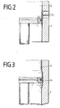
- the contact system is arranged within an insulator 1 in a closed switching chamber.
- the switch has an upper plate-shaped electrical connection 2 and a lower plate-shaped electrical connection 3.
- the part of the switching path which receives the switching arc is formed by a fixed mating contact pin 4, which is conductively connected to the upper exclusion plate 2, in connection with a movable power contact piece 5.
- the arcing contact 5 is conductively connected to a movable cylinder 6, which cooperates with a fixed piston 7, which is attached to the lower connection plate 3, as a switching path pump for generating the required blowing pressure.
- the cylinder 6 is conductively connected to a fork 8 for the introduction of current and force, which in turn is connected to a drive rod 9.
- the drive rod is actuated in the usual way by a hydraulic, pneumatic or spring drive or the like. It is guided inside supports 10, at the lower end of which the drive is attached.
- the fork 8 is in conductive connection with the lower connection plate 3 via sliding contacts 11.
- an insulating nozzle 12 is fixedly connected, from which the gas compressed in the switching section pump 6, 7 emerges when switching off and blows the switching arc that occurs between the contact pieces 4, 5 arises.
- the insulating nozzle 12 has a screen 13 which can move in a fixed cylinder 14 connected to the upper connecting plate 2.
- a parallel contact path to increase the current carrying capacity consisting of two contact pieces 15 and 16, is provided.
- the contact piece 15 is conductively connected to the upper connection plate 2 and is fixed.
- the contact piece 16 is conductively connected to the movable cylinder 6 and moves with it.
- the current flows in the switched-on state between the upper and the lower connection plate 2, 3 in parallel via the two current paths, parallel contact path 14, 15, 16 and the arcing contact path 4, 5.
- the drive rod 9 is moved downward . First, the parallel contact pieces 15, 16 and then the arcing of the power contact paths 4, 5 are separated.
- the switching path pump 6, 7 generates a high blowing pressure in the continuously decreasing volume 21 during the switching-off movement, the compressed insulating gas, for example SF 6 , emerging from the insulating nozzle 12 upwards, blowing the arc and opening 17, 18 in the upper connection plate 2 can escape into the hood 19 of the switching chamber or after cooling also into the other rooms 20 of the pole column.
- the compressed insulating gas for example SF 6
- a number of openings 22 are arranged in the pump cylinder 6 so that they have no function during most of the switch-on stroke and only become effective shortly before the end position is reached.
- a simple constructive solution consists in a ring of bores 22 which, in the end switch-on position, are just above the Pistons 7 lie. Due to this inflow cross section, which should be a multiple of the inflow cross section through the nozzle 12, a pressure equalization between the pump volume 21 and the other spaces of the pole column can be established in a short time at the end of the switch-on stroke. In contrast, during the switch-on stroke, before the bores 22 overflow the piston 7, they connect spaces of the same pressure and are ineffective.
- the openings may be round or of some other shape, e.g. be rectangular.
- the rectangular shape allows the largest inflow cross-section with the smallest stroke, while round bores are preferred when using a sealing ring 23 on the circumference of the piston 7.
- the openings can be distributed in one or more rows on the circumference of the pump cylinder 6.
Landscapes
- Circuit Breakers (AREA)
Applications Claiming Priority (2)
| Application Number | Priority Date | Filing Date | Title |
|---|---|---|---|
| DE3346353 | 1983-12-22 | ||
| DE19833346353 DE3346353A1 (de) | 1983-12-22 | 1983-12-22 | Autopneumatischer druckgasschalter |
Publications (1)
| Publication Number | Publication Date |
|---|---|
| EP0154004A1 true EP0154004A1 (fr) | 1985-09-11 |
Family
ID=6217658
Family Applications (1)
| Application Number | Title | Priority Date | Filing Date |
|---|---|---|---|
| EP84114610A Withdrawn EP0154004A1 (fr) | 1983-12-22 | 1984-12-01 | Coupe circuit à gaz comprimé automatique |
Country Status (4)
| Country | Link |
|---|---|
| EP (1) | EP0154004A1 (fr) |
| JP (1) | JPS60154424A (fr) |
| DE (1) | DE3346353A1 (fr) |
| IN (1) | IN160229B (fr) |
Cited By (1)
| Publication number | Priority date | Publication date | Assignee | Title |
|---|---|---|---|---|
| EP2312603A1 (fr) * | 2009-10-15 | 2011-04-20 | ABB Technology AG | Interrupteur-sectionneur rotatif |
Families Citing this family (3)
| Publication number | Priority date | Publication date | Assignee | Title |
|---|---|---|---|---|
| DE9210086U1 (de) * | 1992-07-22 | 1993-11-25 | Siemens AG, 80333 München | Hochspannungs-Leistungsschalter |
| FR2694987B1 (fr) * | 1992-08-21 | 1994-10-07 | Alsthom Gec | Disjoncteur à haute tension ayant une chambre de coupure à volume de soufflage variable. |
| DE102017212021A1 (de) | 2017-07-13 | 2019-01-17 | Siemens Aktiengesellschaft | Anordnung und Verfahren zum Dämpfen von Schaltbewegungen in Hochspannungsleistungsschaltern |
Citations (6)
| Publication number | Priority date | Publication date | Assignee | Title |
|---|---|---|---|---|
| FR2272477A1 (fr) * | 1974-05-22 | 1975-12-19 | Gratzmuller J | |
| US3946183A (en) * | 1974-04-05 | 1976-03-23 | Westinghouse Electric Corporation | Puffer piston gas blast circuit interrupter with insulating nozzle member |
| FR2352386A1 (fr) * | 1975-12-29 | 1977-12-16 | Merlin Gerin | Disjoncteur electrique a dispositif d'autosoufflage muni d'espaces de compression et d'aspiration de gaz isolant |
| DE2844323A1 (de) * | 1977-12-12 | 1979-06-13 | Sprecher & Schuh Ag | Druckgasschalter |
| EP0016983A1 (fr) * | 1979-03-09 | 1980-10-15 | Licentia Patent-Verwaltungs-GmbH | Disjoncteur à gaz comprimé autopneumatique |
| EP0130842A2 (fr) * | 1983-07-05 | 1985-01-09 | Westinghouse Electric Corporation | Interrupteur de haute tension à soufflage de gaz |
Family Cites Families (4)
| Publication number | Priority date | Publication date | Assignee | Title |
|---|---|---|---|---|
| JPS5471373A (en) * | 1977-11-17 | 1979-06-07 | Mitsubishi Electric Corp | Gas breaker |
| DE3127962A1 (de) * | 1981-07-10 | 1983-01-27 | Siemens AG, 1000 Berlin und 8000 München | Elektrischer druckgasschalter |
| DE3129902A1 (de) * | 1981-07-24 | 1983-02-10 | Siemens AG, 1000 Berlin und 8000 München | Hochspannungs-leistungsschalter |
| US4440997A (en) * | 1982-05-28 | 1984-04-03 | Brown Boveri Electric Inc. | Puffer interrupter with arc energy assist |
-
1983
- 1983-12-22 DE DE19833346353 patent/DE3346353A1/de active Granted
-
1984
- 1984-11-23 IN IN804/CAL/84A patent/IN160229B/en unknown
- 1984-12-01 EP EP84114610A patent/EP0154004A1/fr not_active Withdrawn
- 1984-12-17 JP JP26468784A patent/JPS60154424A/ja active Pending
Patent Citations (6)
| Publication number | Priority date | Publication date | Assignee | Title |
|---|---|---|---|---|
| US3946183A (en) * | 1974-04-05 | 1976-03-23 | Westinghouse Electric Corporation | Puffer piston gas blast circuit interrupter with insulating nozzle member |
| FR2272477A1 (fr) * | 1974-05-22 | 1975-12-19 | Gratzmuller J | |
| FR2352386A1 (fr) * | 1975-12-29 | 1977-12-16 | Merlin Gerin | Disjoncteur electrique a dispositif d'autosoufflage muni d'espaces de compression et d'aspiration de gaz isolant |
| DE2844323A1 (de) * | 1977-12-12 | 1979-06-13 | Sprecher & Schuh Ag | Druckgasschalter |
| EP0016983A1 (fr) * | 1979-03-09 | 1980-10-15 | Licentia Patent-Verwaltungs-GmbH | Disjoncteur à gaz comprimé autopneumatique |
| EP0130842A2 (fr) * | 1983-07-05 | 1985-01-09 | Westinghouse Electric Corporation | Interrupteur de haute tension à soufflage de gaz |
Cited By (2)
| Publication number | Priority date | Publication date | Assignee | Title |
|---|---|---|---|---|
| EP2312603A1 (fr) * | 2009-10-15 | 2011-04-20 | ABB Technology AG | Interrupteur-sectionneur rotatif |
| WO2011044983A1 (fr) * | 2009-10-15 | 2011-04-21 | Abb Technology Ag | Interrupteur-sectionneur rotatif |
Also Published As
| Publication number | Publication date |
|---|---|
| JPS60154424A (ja) | 1985-08-14 |
| DE3346353C2 (fr) | 1992-08-06 |
| IN160229B (fr) | 1987-07-04 |
| DE3346353A1 (de) | 1985-07-04 |
Similar Documents
| Publication | Publication Date | Title |
|---|---|---|
| DE3247121C2 (fr) | ||
| DE7906561U1 (de) | Autopneumatischer Druckgasschalter | |
| DE19536673A1 (de) | Leistungsschalter | |
| DE68911479T2 (de) | Hochspannungsdruckgasschalter. | |
| DE1199368B (de) | Hochspannungsleistungsschalter | |
| DE3872090T2 (de) | Druckgasschalter fuer hoch- oder mittelspannung mit von der lichtbogenenergie entnommener ausschaltenergie. | |
| DE19547098A1 (de) | Leistungsschalter mit einem Einschaltwiderstand | |
| DE3346353C2 (fr) | ||
| DE2621098A1 (de) | Druckgasschalter | |
| EP0554686B1 (fr) | Interrupteur à gaz sous pression | |
| DE1122134B (de) | Leistungsschalter | |
| DE1216964C2 (de) | Elektrischer schalter | |
| EP0744759A1 (fr) | Disjoncteur pour haute tension avec chambre de réchauffement fixe | |
| EP0035581B1 (fr) | Disjoncteur à gaz comprimé | |
| DE1913969A1 (de) | Elektrischer Schalter | |
| DE69106436T2 (de) | Mittelspannungsschalter. | |
| CH645755A5 (de) | Autopneumatischer druckgasschalter. | |
| DE3887245T3 (de) | Lichtbogenlöscheinrichtung für Schalter. | |
| DE3321740A1 (de) | Druckgasschalter | |
| DE4402123C2 (de) | Hochspannungs-Leistungsschalter mit einem Heizraum | |
| DE4402121A1 (de) | Elektrischer Hochspannungs-Leistungsschalter mit einem Heizraum und einer Kompressionsvorrichtung | |
| DE2745343A1 (de) | Umlenkgetriebe fuer einen elektrischen leistungsschalter mit daempfungswiderstaenden | |
| DE1223918B (de) | Elektrischer Schalter mit einer Kompressions-einrichtung | |
| DE3722541C2 (fr) | ||
| DE3017980A1 (de) | Elektrischer schalter mit selbsterzeugtem loeschgasstrom |
Legal Events
| Date | Code | Title | Description |
|---|---|---|---|
| PUAI | Public reference made under article 153(3) epc to a published international application that has entered the european phase |
Free format text: ORIGINAL CODE: 0009012 |
|
| AK | Designated contracting states |
Designated state(s): CH FR GB IT LI |
|
| STAA | Information on the status of an ep patent application or granted ep patent |
Free format text: STATUS: THE APPLICATION IS DEEMED TO BE WITHDRAWN |
|
| 18D | Application deemed to be withdrawn |
Effective date: 19860512 |
|
| RIN1 | Information on inventor provided before grant (corrected) |
Inventor name: HOFFMANN, DIETRICH, DIPL.-ING. |