EP0153739A2 - Flexible conduit and fitting - Google Patents
Flexible conduit and fitting Download PDFInfo
- Publication number
- EP0153739A2 EP0153739A2 EP85102166A EP85102166A EP0153739A2 EP 0153739 A2 EP0153739 A2 EP 0153739A2 EP 85102166 A EP85102166 A EP 85102166A EP 85102166 A EP85102166 A EP 85102166A EP 0153739 A2 EP0153739 A2 EP 0153739A2
- Authority
- EP
- European Patent Office
- Prior art keywords
- flexible conduit
- inner layer
- fitting
- reinforcement
- flexible
- Prior art date
- Legal status (The legal status is an assumption and is not a legal conclusion. Google has not performed a legal analysis and makes no representation as to the accuracy of the status listed.)
- Granted
Links
Images
Classifications
-
- F—MECHANICAL ENGINEERING; LIGHTING; HEATING; WEAPONS; BLASTING
- F16—ENGINEERING ELEMENTS AND UNITS; GENERAL MEASURES FOR PRODUCING AND MAINTAINING EFFECTIVE FUNCTIONING OF MACHINES OR INSTALLATIONS; THERMAL INSULATION IN GENERAL
- F16L—PIPES; JOINTS OR FITTINGS FOR PIPES; SUPPORTS FOR PIPES, CABLES OR PROTECTIVE TUBING; MEANS FOR THERMAL INSULATION IN GENERAL
- F16L11/00—Hoses, i.e. flexible pipes
- F16L11/04—Hoses, i.e. flexible pipes made of rubber or flexible plastics
- F16L11/11—Hoses, i.e. flexible pipes made of rubber or flexible plastics with corrugated wall
- F16L11/112—Hoses, i.e. flexible pipes made of rubber or flexible plastics with corrugated wall having reinforcements embedded in the wall
-
- F—MECHANICAL ENGINEERING; LIGHTING; HEATING; WEAPONS; BLASTING
- F16—ENGINEERING ELEMENTS AND UNITS; GENERAL MEASURES FOR PRODUCING AND MAINTAINING EFFECTIVE FUNCTIONING OF MACHINES OR INSTALLATIONS; THERMAL INSULATION IN GENERAL
- F16L—PIPES; JOINTS OR FITTINGS FOR PIPES; SUPPORTS FOR PIPES, CABLES OR PROTECTIVE TUBING; MEANS FOR THERMAL INSULATION IN GENERAL
- F16L33/00—Arrangements for connecting hoses to rigid members; Rigid hose connectors, i.e. single members engaging both hoses
- F16L33/22—Arrangements for connecting hoses to rigid members; Rigid hose connectors, i.e. single members engaging both hoses with means not mentioned in the preceding groups for gripping the hose between inner and outer parts
-
- Y—GENERAL TAGGING OF NEW TECHNOLOGICAL DEVELOPMENTS; GENERAL TAGGING OF CROSS-SECTIONAL TECHNOLOGIES SPANNING OVER SEVERAL SECTIONS OF THE IPC; TECHNICAL SUBJECTS COVERED BY FORMER USPC CROSS-REFERENCE ART COLLECTIONS [XRACs] AND DIGESTS
- Y10—TECHNICAL SUBJECTS COVERED BY FORMER USPC
- Y10T—TECHNICAL SUBJECTS COVERED BY FORMER US CLASSIFICATION
- Y10T29/00—Metal working
- Y10T29/49—Method of mechanical manufacture
- Y10T29/49826—Assembling or joining
- Y10T29/49863—Assembling or joining with prestressing of part
- Y10T29/4987—Elastic joining of parts
-
- Y—GENERAL TAGGING OF NEW TECHNOLOGICAL DEVELOPMENTS; GENERAL TAGGING OF CROSS-SECTIONAL TECHNOLOGIES SPANNING OVER SEVERAL SECTIONS OF THE IPC; TECHNICAL SUBJECTS COVERED BY FORMER USPC CROSS-REFERENCE ART COLLECTIONS [XRACs] AND DIGESTS
- Y10—TECHNICAL SUBJECTS COVERED BY FORMER USPC
- Y10T—TECHNICAL SUBJECTS COVERED BY FORMER US CLASSIFICATION
- Y10T29/00—Metal working
- Y10T29/49—Method of mechanical manufacture
- Y10T29/49826—Assembling or joining
- Y10T29/49863—Assembling or joining with prestressing of part
- Y10T29/49874—Prestressing rod, filament or strand
Definitions
- This invention relates generally to the field of flexible conduits and more particularly to the field of flexible conduits formed primarily from plastic materials and a fitting for cooperation therewith.
- the flexible conduit is desired to be used in operating conditions wherein elongation of the flexible conduit is required to be limited to less than 10% when subjected to tensile forces exceeding 75 pounds, it is necessary that the flexible conduit and the fitting must be able to resist the tendency to separate or leak when subjected to the same forces.
- This invent Ion provides of llexible conduit formed primarily from plastic materlals but provided with means to insure a low eloneation tactor even when subjected to tensile forces exceeding 75 pounds.
- this low elongation factor is obtained by securing at least one longitudinally extending reinforcement tape to the outer surface of an inner continuous layer of a flexible material.
- a fitting is provided for use with the flexible conduit wherein the fitting is provided with a male member having a threaded outer surface in engagement with a portion of the inner surface of the inner layer.
- the outer diameters of portions of the threaded outer surface are greater than the inner diameter of the inner layer so that when the flexible conduit is positioned over the male member, portions of the flexible conduit over the male member have been stretched or enlarged. Since the flexible conduit is formed from materials having a tendency to return to their original configuration, the stretched portions will exert compressive forces on the associated outer surfaces' of the male member to resist separation between the flexible conduit and the fitting. Also, since the reinforcement tape follows the profile of the threaded outer surface, the reinforcement tape is formed into a corrugated configuration. As tensile forces are increased, the reinforcement tapes begin to return to a straight configuration which increases the contact pressure of the reinforcement tape and the inner layer against the male member of the fitting. This contact pressure increases as the tensile forces increase to provide additional resistance against the separation of the flexible conduit and the fitting.
- the flexible conduit comprises an inner layer comprising a flexible tube of PVC material with two longitudinally extending reinforcement tapes secured to the outer surface of the flexible tube.
- the tapes are spaced evenly from each other so that they are substantially 180" apart.
- a spiral coil of a rigid plastic material is secured to the outer surface of the flexible tube and the reinforcing taped and exerts sufficient force on the flexible tube so that a spirally extending protuberance extends inwardly from the inner surface of the flexible tube.
- the flexible tube, the reinforcement tapes and the spiral coil are encapsulated by a covering material that is in contact with the outer exposed surfaces of the flexible tube, the reinforcement tapes and the spiral coil
- a fitting is provided for cooperation with an associated portion of the flexible conduit to resist any forces trying to separate the flexible conduit and the fitting when in assembled relationship.
- the flexible conduit and the fitting are assembled and cooperate in the manner described above.
- the preferred embodiment of the invention illustrated in the drawing comprises a flexible conduit 2 having an inner layer 4 which comprises an extruded continuous conduit formed from a flexible PVC material.
- the inner layer 4 is provided with low elongation characteristics by securing to the outer surface 6 thereof a reinforcement tape 8 which extends longitudinally of the inner layer.
- the tape 8 comprises a plurality of continuous strands 10 of a material having low elongation characteristics which in the preferred embodiment is rayon. Other materials such as synthetic or natural fibers and metals may be used as long as they have low elongation characteristics and are compatible with the other materials in the flexible conduit.
- the continuous strands 8 are secured to the outer surface of the inner layer 4 by any suitable means, such as by bonding.
- two reinforcement tapes are secured on opposite sides, spured 180" apart, of the outer surtace ( 1 of the inner layer 4. More than two reintorcement tapes 8 may be securel to the outer surface 6 but while additional tapes; provide greater resistance to elongation, they also reduce the flexibility of the conduit. Sufficient elongation characteristics may be obtained from only one tape but this is less preferred.
- a spiral coil 14 is secured to the outer surface 6 of the inner layer 4 by any suitable means such as by bonding.
- the spiral coil 14 is formed as a rigid member to provide crush resistance for the inner layer 4 and the reinforcement tapes 8.
- the inner diameter of the spiral coil 14 is slightly smaller than the outer diameter of inner layer 4 so that when the spiral coil 14 is placed over the inner layer 4 it displaces the adjacent portion of the inner layer 4. As illustrated in Figs. 1 and 3, this displacement forms a spirally extending protuberance 16 extending inwardly from the inner surface 18 of the inner layer 4 for a purpose to be described.
- the protuberance 16 is small enough so that wires may be readily pulled through the flexible conduit but minimizes the contact between the inner surface of the inner layer 4 and the wires during such operation.
- the fitting 22 is an integral unit having an inner male member 24. Adjacent to the end 26, the male member 24 is provided with a tapered outer surface 28 having its smallest diameter adjacent to the end 26.
- a spiral groove 30 is formed in the outer surface of the male member 24. The portion of the outer surface of the male member 24 between adlacent portions of the spiral groove 30 is formed by two slanted walls 38 and 34 which meet to form a spirally extending continuous apex 36. As illustrated in Figs. 4 and 5, the largest outer diameter of the male member 24 is at the apex 36.
- the fitting 22 has an outer wall 38 surrounding the male member 24 and spaced therefrom to form an annular space 40 therebetween.
- the outer wall 38 is provided with a tapered inner surface 42 with the largest inner diameter of the inner surface 42 being adjacent to the end 44 of the outer wall 38.
- a resilient material 46 is located in the innermost portion of the annular space 40 and is in contact with the outer surface of the male member 24 and the inner surface 42 of the outer wall 38.
- the distance between the apex 36 and the inner surface 42 is smaller than the combined thickness of the inner layer 4, the reinforcement tape 8, the spiral coil 14 and the cover 20 for a purpose described below.
- the outer surface of the fitting 22 adjacent to the end 48 is provided with threads 50 which are designed for the type of service in which the flexible conduit 2 is to be used.
- the surface 52 is shaped conventionally (not shown) to accommodate a proper tool when the flexible conduit 2 is being assembled into its working environment.
- a fitting 22 is provided on each end of the flexible conduit.
- the assembled relationship between the flexible conduit 2 and the fitting 22 is illustrated in Fig. 5.
- the inner diameter of the inner layer 4 is designed to be only slightly larger than the smallest diameter of the tapered surface 28 so that the inner surface 18 of the inner layer 4 contacts the tapered surface 28 adjacent to the end 26 of the fitting 22. Sufficient force is applied in a longitudinal direction to start the flexible conduit 2 moving over the tapered surface 28.
- the inner diameter of the portions of the flexible conduit 2 between the of mal corl 14 is gradually mereased and the material in those port roms is stretclued
- the inner diameter of the protuberance 16 is slightly smaller than the smallest outer diameter of the groove 30 to insure contact between the protuberance 16 and the surface of the groove 30.
- the difference in diameters between the protuberance 16 and the groove 30 is designed to be minimum, only enough to insure contact, in order to avoid excessive assembly forces. Therefore, in addition to the longitudinal force, described above, a rotational force is also applied to the flexible conduit 2 so that the protuberance 16 follows the contour of the groove 30. As illustrated in Fig. 5, the portions of the inner layer 4, the reinforcement tape 8 and the cover 20 between adjacent coils of the spiral coil 14 follow the contour of the slanted surfaces 32 and 34 and the apex 36.
- the inner surface of the inner layer 4 is in firm engagement with the associated surfaces of the male member 24 including the surfaces 32 and 34 and the spiral apex 36. Because of this tendency, compressive forces are generated by the inner layer 4 and the cover 20 against the male member 24 to hold the flexible conduit 2 and the fitting 22 in the assembled relationship against forces trying to separate them. The application of the longitudinal and rotational forces is continued until the leading edge 54 of the flexible tube is embedded in the resilient material 46 to insure a seal.
- the inner surface 42 is tapered.
- the fitting is designed so that in most sizes, the greatest distance between the apex 36 and the inner surface 42 is less than the combined thickness of the inner layer 4, the spiral coil 1 14 and the cover 10.
- This design adds addctional resistance to any forces tryinq to sepatate the flexible conduit 2 from its assembled relationship in the fitting 22. Satisfactory results will be obtained if only the average distance between the apex 36 and the inner surface 42 is less than the combined thickness of the inner layer 4, the spiral coil 14 and the cover 20. In those designs wherein the foregoing relationship does not exist, the greatest distance between the apex 36 and the inner surface 42 is less than the combined thickness of the inner layer 4, the reinforcement tape 8, the spiral coil 14 and the cover 20.
- the reinforcement tapes 8 follow the profile of the outer surface of the male member 24 so that the reinforcement tape is formed into a corrugated configuration.
- the reinforcement tapes begin tc return to a straight configuration which increases the contact pressure of the reinforcement tape and the inner layer against the male member of the fitting. This contact pressure increases as the tensile forces increase to provide additional resistance against the separation of the flexible conduit and the fitting.
- the inner layer 4 comprises an extruded flexible PVC material in sizes having diameters of about 3/8 inch to 2.0 inch and a wall thickness of about 0.020 to 0.030 inch.
- the reinforcement tape 8 comprises a plurality of strands of continuous rayon filnments bonded together to form a flat tape having a width of about 0.100 to 0.250 inch and a thickness less than about 0.014 inch. It is understood that the use of a reinforcement tape formed from continuous strands in the preferred embodiment is for illustration purposes only and the tape can be formed in any manner, such as by weaving, so long as it posesses the desired elongation characteristics.
- the reinforcement tape can be made from variety otherthan ryon, such as any synthetre or natural fibers and mtals, as lung as the desired elongation characteristics are obtained.
- Two tapes spaced 180° apart are secured to the outer surface of the inner layer 4 using an adhesive.
- the reinforcement tapes 8 extend in a longitudinal direction.
- the spiral coil 14 is a rigid PVC coil bonded to the outer surfaces of the inner layer 4 and the reinforcement tapes 8 with an adhesive.
- the encapsulating cover 20 comprises a flexible PVC material, similar to that in the inner layer 4, and is applied while hot so as to bond to the outer exposed surfaces of the inner layer 4, the reinforcement tapes 8 and the spiral coil 14.
- PVC polyvinyl styrene
- spiral coil 14 and cover 20 are for illustration purposes only and they can be formed from any other materials having similar characteristics such as nylon, polyester and aramid.
- the fitting 22 is integrally molded from nylon or other suitable material.
- An elastomer 46 comprising siliccne or other suitable material, is inserted into the annular space 40 while still in the uncured state so that it will bond to and conform to the shape of the surfaces it contacts and will cure to provide a resilient member.
- a flexible conduit with two reinforcement tapes and fitting formed in accordance with the foregoing description has a tensile strength of at least 125 pounds, i.e., fitting pull off or conduit failure not less than 125 pounds with a maximum of 108 elongation.
Landscapes
- Engineering & Computer Science (AREA)
- General Engineering & Computer Science (AREA)
- Mechanical Engineering (AREA)
- Rigid Pipes And Flexible Pipes (AREA)
- Details Of Indoor Wiring (AREA)
- Laminated Bodies (AREA)
Abstract
Description
- This invention relates generally to the field of flexible conduits and more particularly to the field of flexible conduits formed primarily from plastic materials and a fitting for cooperation therewith.
- For many years, manufacturers have been making flexible conduits from various types of materials. There are several reasons, such as costs, fatigue/flexure life and weight, why it is desirable to make such flexible conduits from plastic materials, such as PVC, nylon or any extrudable material capable of being readily flexed when in a generally tubular shape. One disadvantage associated with the use of flexible plastic materials to make such flexible conduits is the tendency of these materials to elongate even when subjected to relatively low tensile forces. These elongation characteristics are even greater approaching 100% when such flexible conduits are subjected to tensile forces exceeding 75 pounds. As with all types of conduits, a flexible conduit must be provided with a fitting capable of cooperating with the conduit to provide a suitable connection under the desired operating conditions. Thus, if the flexible conduit is desired to be used in operating conditions wherein elongation of the flexible conduit is required to be limited to less than 10% when subjected to tensile forces exceeding 75 pounds, it is necessary that the flexible conduit and the fitting must be able to resist the tendency to separate or leak when subjected to the same forces.
- This invent Ion provides of llexible conduit formed primarily from plastic materlals but provided with means to insure a low eloneation tactor even when subjected to tensile forces exceeding 75 pounds. In the preferred embodiment, this low elongation factor is obtained by securing at least one longitudinally extending reinforcement tape to the outer surface of an inner continuous layer of a flexible material. A fitting is provided for use with the flexible conduit wherein the fitting is provided with a male member having a threaded outer surface in engagement with a portion of the inner surface of the inner layer. The outer diameters of portions of the threaded outer surface are greater than the inner diameter of the inner layer so that when the flexible conduit is positioned over the male member, portions of the flexible conduit over the male member have been stretched or enlarged. Since the flexible conduit is formed from materials having a tendency to return to their original configuration, the stretched portions will exert compressive forces on the associated outer surfaces' of the male member to resist separation between the flexible conduit and the fitting. Also, since the reinforcement tape follows the profile of the threaded outer surface, the reinforcement tape is formed into a corrugated configuration. As tensile forces are increased, the reinforcement tapes begin to return to a straight configuration which increases the contact pressure of the reinforcement tape and the inner layer against the male member of the fitting. This contact pressure increases as the tensile forces increase to provide additional resistance against the separation of the flexible conduit and the fitting.
- In the preferred embodiment, the flexible conduit comprises an inner layer comprising a flexible tube of PVC material with two longitudinally extending reinforcement tapes secured to the outer surface of the flexible tube. The tapes are spaced evenly from each other so that they are substantially 180" apart. A spiral coil of a rigid plastic material is secured to the outer surface of the flexible tube and the reinforcing taped and exerts sufficient force on the flexible tube so that a spirally extending protuberance extends inwardly from the inner surface of the flexible tube. The flexible tube, the reinforcement tapes and the spiral coil are encapsulated by a covering material that is in contact with the outer exposed surfaces of the flexible tube, the reinforcement tapes and the spiral coil As described above, a fitting is provided for cooperation with an associated portion of the flexible conduit to resist any forces trying to separate the flexible conduit and the fitting when in assembled relationship. The flexible conduit and the fitting are assembled and cooperate in the manner described above.
- It is an object of this invention to provide a flexible conduit having low elongation characteristics.
- It is another object of this invention to provide a flexible conduit having low elongation characteristics made from plastic materials.
- It is a further object of this invention to provide a fitting for use with such flexible conduit and cooperating therewith to provide the necessary resistance to separation between the flexible conduit and the fitting.
- It is another object of this invention to provide a method for assembling a flexible conduit and a fitting to provide a sealed, liquid tight joint with high resistance to separation between the flexible conduit and the fitting.
- Other features and advantages of the invention will be apparent from the following more particular description of preferred embodiments as illustrated in the accompanying drawings in which like reference characters refer to the same parts throughout the various views. The drawings arc not necessarily to scales, cmphasis instead beme placed upon illustrating the principles of the invention.
-
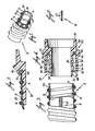
- Fig. 1 is a pictorial view with parts in section of a flexible conduit of this invention;
- Fig. 2 is a cross-sectional view of a reinforcement tape used in this invention;
- Fig. 3 is a side elevation of the flexible conduit of Fig. 1 with parts in section;
- Fig. 4 is a cross-sectional view of a fitting of this invention; and
- Fig. 5 is a cross-sectional view illustrating a portion of the flexible conduit and fitting in the assembled relationship.
- The preferred embodiment of the invention illustrated in the drawing comprises a flexible conduit 2 having an inner layer 4 which comprises an extruded continuous conduit formed from a flexible PVC material. The inner layer 4 is provided with low elongation characteristics by securing to the outer surface 6 thereof a
reinforcement tape 8 which extends longitudinally of the inner layer. Thetape 8 comprises a plurality ofcontinuous strands 10 of a material having low elongation characteristics which in the preferred embodiment is rayon. Other materials such as synthetic or natural fibers and metals may be used as long as they have low elongation characteristics and are compatible with the other materials in the flexible conduit. Thecontinuous strands 8 are secured to the outer surface of the inner layer 4 by any suitable means, such as by bonding. In the preferred embodiment, two reinforcement tapes are secured on opposite sides, spured 180" apart, of the outer surtace (1 of the inner layer 4. More than tworeintorcement tapes 8 may be securel to the outer surface 6 but while additional tapes; provide greater resistance to elongation, they also reduce the flexibility of the conduit. Sufficient elongation characteristics may be obtained from only one tape but this is less preferred. - A
spiral coil 14 is secured to the outer surface 6 of the inner layer 4 by any suitable means such as by bonding. Thespiral coil 14 is formed as a rigid member to provide crush resistance for the inner layer 4 and thereinforcement tapes 8. The inner diameter of thespiral coil 14 is slightly smaller than the outer diameter of inner layer 4 so that when thespiral coil 14 is placed over the inner layer 4 it displaces the adjacent portion of the inner layer 4. As illustrated in Figs. 1 and 3, this displacement forms a spirally extending protuberance 16 extending inwardly from theinner surface 18 of the inner layer 4 for a purpose to be described. Also, the protuberance 16 is small enough so that wires may be readily pulled through the flexible conduit but minimizes the contact between the inner surface of the inner layer 4 and the wires during such operation. After the inner layer 4, thereinforcement tapes 8 and thespiral coil 14 have been assembled into a unit, the outer surface of the unit is encapsulated within acover 20 which is preferably made from the same material as the inner layer 4 so as to be compatible therewith. - In Figs. 4 and 5, there is illustrated a
fitting 22 to be used with the flexible conduit 2. The fitting 22 is an integral unit having an innermale member 24. Adjacent to theend 26, themale member 24 is provided with a taperedouter surface 28 having its smallest diameter adjacent to theend 26. Aspiral groove 30 is formed in the outer surface of themale member 24. The portion of the outer surface of themale member 24 between adlacent portions of thespiral groove 30 is formed by twoslanted walls continuous apex 36. As illustrated in Figs. 4 and 5, the largest outer diameter of themale member 24 is at theapex 36. Thefitting 22 has anouter wall 38 surrounding themale member 24 and spaced therefrom to form anannular space 40 therebetween. Theouter wall 38 is provided with a taperedinner surface 42 with the largest inner diameter of theinner surface 42 being adjacent to theend 44 of theouter wall 38. Aresilient material 46 is located in the innermost portion of theannular space 40 and is in contact with the outer surface of themale member 24 and theinner surface 42 of theouter wall 38. The distance between theapex 36 and theinner surface 42 is smaller than the combined thickness of the inner layer 4, thereinforcement tape 8, thespiral coil 14 and thecover 20 for a purpose described below. The outer surface of thefitting 22 adjacent to theend 48 is provided withthreads 50 which are designed for the type of service in which the flexible conduit 2 is to be used. Also, thesurface 52 is shaped conventionally (not shown) to accommodate a proper tool when the flexible conduit 2 is being assembled into its working environment. Afitting 22 is provided on each end of the flexible conduit. - The assembled relationship between the flexible conduit 2 and the
fitting 22 is illustrated in Fig. 5. The inner diameter of the inner layer 4 is designed to be only slightly larger than the smallest diameter of thetapered surface 28 so that theinner surface 18 of the inner layer 4 contacts thetapered surface 28 adjacent to theend 26 of thefitting 22. Sufficient force is applied in a longitudinal direction to start the flexible conduit 2 moving over the taperedsurface 28. As the flexible conduit 2 moves over the taperedsurface 28, the inner diameter of the portions of the flexible conduit 2 between the of mal corl 14 is gradually mereased and the material in those port roms is stretclued The inner diameter of the protuberance 16 is slightly smaller than the smallest outer diameter of thegroove 30 to insure contact between the protuberance 16 and the surface of thegroove 30. Since thespiral coil 14 will not expand, the difference in diameters between the protuberance 16 and thegroove 30 is designed to be minimum, only enough to insure contact, in order to avoid excessive assembly forces. Therefore, in addition to the longitudinal force, described above, a rotational force is also applied to the flexible conduit 2 so that the protuberance 16 follows the contour of thegroove 30. As illustrated in Fig. 5, the portions of the inner layer 4, thereinforcement tape 8 and thecover 20 between adjacent coils of thespiral coil 14 follow the contour of the slanted surfaces 32 and 34 and the apex 36. Since the material in the inner layer 4 and thecover 20 has a natural tendency to resile, that is, to return to its original dimensions, the inner surface of the inner layer 4 is in firm engagement with the associated surfaces of themale member 24 including thesurfaces spiral apex 36. Because of this tendency, compressive forces are generated by the inner layer 4 and thecover 20 against themale member 24 to hold the flexible conduit 2 and the fitting 22 in the assembled relationship against forces trying to separate them. The application of the longitudinal and rotational forces is continued until the leading edge 54 of the flexible tube is embedded in theresilient material 46 to insure a seal. - As described above, the
inner surface 42 is tapered. However, the fitting is designed so that in most sizes, the greatest distance between the apex 36 and theinner surface 42 is less than the combined thickness of the inner layer 4, thespiral coil 1 14 and thecover 10. This design adds addctional resistance to any forces tryinq to sepatate the flexible conduit 2 from its assembled relationship in the fitting 22. Satisfactory results will be obtained if only the average distance between the apex 36 and theinner surface 42 is less than the combined thickness of the inner layer 4, thespiral coil 14 and thecover 20. In those designs wherein the foregoing relationship does not exist, the greatest distance between the apex 36 and theinner surface 42 is less than the combined thickness of the inner layer 4, thereinforcement tape 8, thespiral coil 14 and thecover 20. In addition to the frictional forces generated by the compressive forces generated by the inner layer 4 and thecover 20, thereinforcement tapes 8 follow the profile of the outer surface of themale member 24 so that the reinforcement tape is formed into a corrugated configuration. As tensile forces are increased, the reinforcement tapes begin tc return to a straight configuration which increases the contact pressure of the reinforcement tape and the inner layer against the male member of the fitting. This contact pressure increases as the tensile forces increase to provide additional resistance against the separation of the flexible conduit and the fitting. - In a preferred embodiment of the invention, the inner layer 4 comprises an extruded flexible PVC material in sizes having diameters of about 3/8 inch to 2.0 inch and a wall thickness of about 0.020 to 0.030 inch. The
reinforcement tape 8 comprises a plurality of strands of continuous rayon filnments bonded together to form a flat tape having a width of about 0.100 to 0.250 inch and a thickness less than about 0.014 inch. It is understood that the use of a reinforcement tape formed from continuous strands in the preferred embodiment is for illustration purposes only and the tape can be formed in any manner, such as by weaving, so long as it posesses the desired elongation characteristics. Also, the reinforcement tape can be made from materiale otherthan ryon, such as any synthetre or natural fibers and mtals, as lung as the desired elongation characteristics are obtained. Two tapes spaced 180° apart are secured to the outer surface of the inner layer 4 using an adhesive. Thereinforcement tapes 8 extend in a longitudinal direction. Thespiral coil 14 is a rigid PVC coil bonded to the outer surfaces of the inner layer 4 and thereinforcement tapes 8 with an adhesive. The encapsulatingcover 20 comprises a flexible PVC material, similar to that in the inner layer 4, and is applied while hot so as to bond to the outer exposed surfaces of the inner layer 4, thereinforcement tapes 8 and thespiral coil 14. It is understood that use of PVC for the flexible conduit 2,spiral coil 14 and cover 20 is for illustration purposes only and they can be formed from any other materials having similar characteristics such as nylon, polyester and aramid. The fitting 22 is integrally molded from nylon or other suitable material. Anelastomer 46, comprising siliccne or other suitable material, is inserted into theannular space 40 while still in the uncured state so that it will bond to and conform to the shape of the surfaces it contacts and will cure to provide a resilient member. - A flexible conduit with two reinforcement tapes and fitting formed in accordance with the foregoing description has a tensile strength of at least 125 pounds, i.e., fitting pull off or conduit failure not less than 125 pounds with a maximum of 108 elongation.
- While the preferred embodiments of the invention have been illustrated and described herein, it may be otherwise embodied and practiced within the scope of the following claims.
Claims (21)
Applications Claiming Priority (2)
| Application Number | Priority Date | Filing Date | Title |
|---|---|---|---|
| US06/584,208 US4599784A (en) | 1984-02-27 | 1984-02-27 | Method of assembling flexible conduit and fitting |
| US584208 | 2000-05-31 |
Publications (3)
| Publication Number | Publication Date |
|---|---|
| EP0153739A2 true EP0153739A2 (en) | 1985-09-04 |
| EP0153739A3 EP0153739A3 (en) | 1986-05-14 |
| EP0153739B1 EP0153739B1 (en) | 1989-04-26 |
Family
ID=24336361
Family Applications (1)
| Application Number | Title | Priority Date | Filing Date |
|---|---|---|---|
| EP85102166A Expired EP0153739B1 (en) | 1984-02-27 | 1985-02-27 | Flexible conduit and fitting |
Country Status (7)
| Country | Link |
|---|---|
| US (1) | US4599784A (en) |
| EP (1) | EP0153739B1 (en) |
| CA (1) | CA1232211A (en) |
| DE (1) | DE3569809D1 (en) |
| DK (1) | DK161907C (en) |
| ES (1) | ES8607511A1 (en) |
| NO (1) | NO167525C (en) |
Cited By (5)
| Publication number | Priority date | Publication date | Assignee | Title |
|---|---|---|---|---|
| WO1992014958A1 (en) * | 1991-02-14 | 1992-09-03 | Alfa-Laval Agriculture International Ab | Milking machine hose |
| EP0877188A1 (en) | 1997-05-08 | 1998-11-11 | Smiths Industries Public Limited Company | Tubing |
| DE202009007433U1 (en) | 2009-05-17 | 2009-08-27 | Hidde, Axel R., Dr. Ing. | Universal quick connector |
| EP2053293A3 (en) * | 2007-10-25 | 2013-08-07 | Wieland-Werke AG | Adapter piece for connecting pipes |
| EP2628988A1 (en) * | 2013-03-13 | 2013-08-21 | Actervis Gmbh | Water hose |
Families Citing this family (31)
| Publication number | Priority date | Publication date | Assignee | Title |
|---|---|---|---|---|
| JPS62113993A (en) * | 1985-11-13 | 1987-05-25 | 株式会社 トヨツクス | Joint for spirally reinforced hose |
| US5056831A (en) * | 1990-05-02 | 1991-10-15 | Ho Kuei Fang | Fitting construction for connection of pipes and pipe assembly |
| CA2051722A1 (en) * | 1990-12-12 | 1992-06-13 | William R. Gray | Flexible duct |
| US5829483A (en) * | 1992-10-30 | 1998-11-03 | Toyoda Gosei Co., Ltd. | Hose |
| BR9707458A (en) | 1996-01-03 | 1999-07-20 | Flexfab Horizons Int Inc | Light conduit combination of a light conduit and a connector and light conduit forming process |
| JP3261969B2 (en) * | 1996-02-29 | 2002-03-04 | 豊田合成株式会社 | Hose and manufacturing method |
| US6158477A (en) * | 1998-12-18 | 2000-12-12 | Flexible Technologies, Inc. | Flexible duct and method of making same |
| US8321970B2 (en) | 2000-06-13 | 2012-12-04 | Wcm Industries, Inc. | Method and associated apparatus for assembling and testing a plumbing system |
| US20080196161A1 (en) * | 2004-10-22 | 2008-08-21 | Wcm Industries, Inc. | Flexible Bathtub Waste Pipe Assembly for Bathtubs and the Like |
| US8028357B2 (en) * | 2000-06-13 | 2011-10-04 | Wcm Industries, Inc. | Method and associated apparatus for assembling and testing a plumbing system |
| US8166584B2 (en) | 2000-06-13 | 2012-05-01 | Wcm Industries, Inc. | Overflow assembly for bathtubs and the like |
| USD674883S1 (en) | 2004-10-22 | 2013-01-22 | Wcm Industries, Inc. | Flexible bathtub waste pipe assembly |
| US20060186664A1 (en) * | 2005-02-22 | 2006-08-24 | Chin Hsin Huang | Helical stacked composite hoses |
| US9505164B2 (en) | 2009-12-30 | 2016-11-29 | Schauenburg Technology Se | Tapered helically reinforced hose and its manufacture |
| US8453681B2 (en) * | 2009-01-15 | 2013-06-04 | Schouenburg Hose Technology GmbH | Flexible, stretchable, crush resistant hose well suited for medical applications |
| DE102008022663B4 (en) * | 2008-05-07 | 2012-10-31 | Schauenburg Hose Technology Gmbh | Stretch hose |
| US9308698B2 (en) | 2009-01-15 | 2016-04-12 | Schauenburg Hose Technology Gmbh | Method of hose manufacture |
| DE102008027927A1 (en) * | 2008-06-12 | 2009-12-17 | Truplast Kunststofftechnik Gmbh | Kink protection for hoses, in particular vacuum cleaner hoses |
| US9365004B2 (en) | 2009-01-15 | 2016-06-14 | Schauenburg Hose Technology Gmbh | Flexible stretch hose having inwardly extending web portions connecting adjacent pairs of reinforcing coils, with hose properties enhanced by annealing |
| US9964238B2 (en) | 2009-01-15 | 2018-05-08 | Globalmed, Inc. | Stretch hose and hose production method |
| DE102009009108B3 (en) * | 2009-02-16 | 2010-06-17 | Bayer Technology Services Gmbh | Method and device for connecting a flexible profiled hollow cylinder with a cylindrical body, as well as irradiation modules produced thereafter |
| DE102009009790B3 (en) * | 2009-02-20 | 2010-06-17 | Schauenburg Hose Technology Gmbh | Heated tube i.e. electrically heated tube, for use as respiratory tube in medical field, has four reinforcing ribs writhing screw line around flexible tube wall, where two of four reinforcing ribs enclose heated wires for heating tube |
| US8936047B2 (en) * | 2010-06-07 | 2015-01-20 | Kongsberg Actuation Systems Ii, Inc. | Reinforced hose assembly |
| US9909699B2 (en) * | 2011-03-17 | 2018-03-06 | Jay G. Bernhardt | Garden hose with spiral guard |
| CN103615608B (en) * | 2013-11-25 | 2016-04-27 | 林和平 | A kind of plastic telescopic pipe and manufacture method thereof |
| US11041583B2 (en) * | 2016-03-25 | 2021-06-22 | Brent L. Clark | Duct coupling |
| US10563385B1 (en) | 2016-05-17 | 2020-02-18 | Wcm Industries, Inc. | Overflow cover interconnection system |
| US10443220B2 (en) | 2016-08-12 | 2019-10-15 | Wcm Industries, Inc. | Device for providing improved drainage |
| CA3053834C (en) | 2017-01-30 | 2020-09-01 | Globalmed, Inc. | Heated respiratory hose assembly |
| USD1003406S1 (en) | 2020-03-13 | 2023-10-31 | Wcm Industries, Inc. | Cover for a bathtub overflow system |
| US11814832B2 (en) | 2020-03-13 | 2023-11-14 | Wcm Industries, Inc. | Overflow covers and overflow systems for bathtubs |
Citations (14)
| Publication number | Priority date | Publication date | Assignee | Title |
|---|---|---|---|---|
| US2674297A (en) * | 1949-05-06 | 1954-04-06 | Arrowhead Rubber Co | Method of manufacturing ducts |
| GB719638A (en) * | 1951-12-01 | 1954-12-08 | Dunlop Rubber Co | Reinforced flexible tubing |
| GB861770A (en) * | 1958-10-31 | 1961-02-22 | Superflexit | Improvements in end fittings for use with flexible hoses, conduits or the like |
| GB889092A (en) * | 1959-03-26 | 1962-02-07 | Weatherhead Co | Hose and hose end assembly and method of making same |
| DE1855306U (en) * | 1959-08-06 | 1962-07-19 | Neue Argus Gmbh | END COUPLING FOR HOSES EQUIPPED WITH A WIRE FLANGE. |
| US3047026A (en) * | 1959-09-23 | 1962-07-31 | Acme Hamilton Mfg Corp | Flexible hose |
| US3058493A (en) * | 1959-02-11 | 1962-10-16 | Porter Co Inc H K | Flexible reinforced corrugated hose |
| US3083736A (en) * | 1959-02-20 | 1963-04-02 | Fred T Roberts & Company | Corrugated hose with reinforcement in alternate inner corrugations |
| DE6909653U (en) * | 1969-03-06 | 1969-08-07 | Phoenix Gummiwerke Ag | HOSE MADE OF RUBBER OR RUBBER-LIKE PLASTIC |
| GB1166478A (en) * | 1965-11-13 | 1969-10-08 | Tsunehiko Ito | Improvements in or relating to Hose Couplings |
| FR2009606A1 (en) * | 1968-05-29 | 1970-02-06 | Superflexit | |
| DE1966018A1 (en) * | 1969-10-18 | 1971-05-06 | Kessler & Co Tech Chem Gmbh | Reinforced flexible plastic hose |
| DE2522288A1 (en) * | 1974-05-21 | 1975-12-04 | Pirelli | HOSE FOR BRAKING DEVICES OF MOTOR VEHICLES |
| DE2443271B2 (en) * | 1973-09-12 | 1978-05-18 | Parker-Hannifin Corp., Cleveland, Ohio (V.St.A.) | Hose with an inner hose and several layers of reinforcement |
Family Cites Families (17)
| Publication number | Priority date | Publication date | Assignee | Title |
|---|---|---|---|---|
| US2918314A (en) * | 1955-07-29 | 1959-12-22 | Gen Electric | Pipe coupling having a portion of the outer resilient tube in axial tension |
| US3002534A (en) * | 1956-10-29 | 1961-10-03 | Reinhold Engineering & Plastic | Reinforced thermoplastics |
| US2901024A (en) * | 1957-08-15 | 1959-08-25 | Fred T Roberts | Method of making hose |
| US2936812A (en) * | 1957-09-03 | 1960-05-17 | Robert E Roberts | Method and apparatus for making flexible corrugated reenforced hose |
| US3063303A (en) * | 1958-11-05 | 1962-11-13 | Teleflex Inc | Guide conduit for motion transmitting system |
| US3138511A (en) * | 1960-05-05 | 1964-06-23 | Teleflex Inc | Apparatus for making a flexible conduit of helically wound wires |
| US3381716A (en) * | 1962-10-12 | 1968-05-07 | Rock Island Oil & Refining Co | Threaded pipe construction |
| FR1583167A (en) * | 1967-05-05 | 1969-10-24 | Inst Francais Du Petrole | |
| GB1209465A (en) * | 1967-08-11 | 1970-10-21 | Dunlop Co Ltd | Flexible hose |
| US3568722A (en) * | 1968-09-17 | 1971-03-09 | Ppg Industries Inc | Longitudinally reinforced flexible duct |
| US3565119A (en) * | 1968-10-25 | 1971-02-23 | Koch Ind Inc | Filament wound reinforced pipe having a vinyl ester resin inner lining |
| JPS5545635B2 (en) * | 1972-04-07 | 1980-11-19 | ||
| US3988188A (en) * | 1973-01-31 | 1976-10-26 | Samuel Moore And Company | Dimensionally stable, flexible hydraulic hose having improved chemical and temperature resistance |
| US4098298A (en) * | 1973-12-14 | 1978-07-04 | Herbert Vohrer | Hose |
| FR2332846A1 (en) * | 1975-11-28 | 1977-06-24 | Giron Jacques | METHOD OF MOLDING A CONTAINER AND MEANS OF IMPLEMENTATION |
| US4140154A (en) * | 1976-05-13 | 1979-02-20 | Shiro Kanao | Flexible hose |
| US4238260A (en) * | 1978-11-13 | 1980-12-09 | Parker-Hannifin Corporation | Method of making an elastomeric hose |
-
1984
- 1984-02-27 US US06/584,208 patent/US4599784A/en not_active Expired - Fee Related
-
1985
- 1985-02-25 CA CA000475018A patent/CA1232211A/en not_active Expired
- 1985-02-26 DK DK086685A patent/DK161907C/en not_active IP Right Cessation
- 1985-02-26 NO NO850756A patent/NO167525C/en unknown
- 1985-02-26 ES ES540691A patent/ES8607511A1/en not_active Expired
- 1985-02-27 DE DE8585102166T patent/DE3569809D1/en not_active Expired
- 1985-02-27 EP EP85102166A patent/EP0153739B1/en not_active Expired
Patent Citations (14)
| Publication number | Priority date | Publication date | Assignee | Title |
|---|---|---|---|---|
| US2674297A (en) * | 1949-05-06 | 1954-04-06 | Arrowhead Rubber Co | Method of manufacturing ducts |
| GB719638A (en) * | 1951-12-01 | 1954-12-08 | Dunlop Rubber Co | Reinforced flexible tubing |
| GB861770A (en) * | 1958-10-31 | 1961-02-22 | Superflexit | Improvements in end fittings for use with flexible hoses, conduits or the like |
| US3058493A (en) * | 1959-02-11 | 1962-10-16 | Porter Co Inc H K | Flexible reinforced corrugated hose |
| US3083736A (en) * | 1959-02-20 | 1963-04-02 | Fred T Roberts & Company | Corrugated hose with reinforcement in alternate inner corrugations |
| GB889092A (en) * | 1959-03-26 | 1962-02-07 | Weatherhead Co | Hose and hose end assembly and method of making same |
| DE1855306U (en) * | 1959-08-06 | 1962-07-19 | Neue Argus Gmbh | END COUPLING FOR HOSES EQUIPPED WITH A WIRE FLANGE. |
| US3047026A (en) * | 1959-09-23 | 1962-07-31 | Acme Hamilton Mfg Corp | Flexible hose |
| GB1166478A (en) * | 1965-11-13 | 1969-10-08 | Tsunehiko Ito | Improvements in or relating to Hose Couplings |
| FR2009606A1 (en) * | 1968-05-29 | 1970-02-06 | Superflexit | |
| DE6909653U (en) * | 1969-03-06 | 1969-08-07 | Phoenix Gummiwerke Ag | HOSE MADE OF RUBBER OR RUBBER-LIKE PLASTIC |
| DE1966018A1 (en) * | 1969-10-18 | 1971-05-06 | Kessler & Co Tech Chem Gmbh | Reinforced flexible plastic hose |
| DE2443271B2 (en) * | 1973-09-12 | 1978-05-18 | Parker-Hannifin Corp., Cleveland, Ohio (V.St.A.) | Hose with an inner hose and several layers of reinforcement |
| DE2522288A1 (en) * | 1974-05-21 | 1975-12-04 | Pirelli | HOSE FOR BRAKING DEVICES OF MOTOR VEHICLES |
Cited By (7)
| Publication number | Priority date | Publication date | Assignee | Title |
|---|---|---|---|---|
| WO1992014958A1 (en) * | 1991-02-14 | 1992-09-03 | Alfa-Laval Agriculture International Ab | Milking machine hose |
| EP0877188A1 (en) | 1997-05-08 | 1998-11-11 | Smiths Industries Public Limited Company | Tubing |
| EP2053293A3 (en) * | 2007-10-25 | 2013-08-07 | Wieland-Werke AG | Adapter piece for connecting pipes |
| DE202009007433U1 (en) | 2009-05-17 | 2009-08-27 | Hidde, Axel R., Dr. Ing. | Universal quick connector |
| DE102009021700A1 (en) | 2009-05-17 | 2010-11-18 | Hidde, Axel, Dipl.-Ing. | Universal quick-release fitting |
| EP2628988A1 (en) * | 2013-03-13 | 2013-08-21 | Actervis Gmbh | Water hose |
| EP2778491A1 (en) * | 2013-03-13 | 2014-09-17 | Actervis Gmbh | Water hose |
Also Published As
| Publication number | Publication date |
|---|---|
| DE3569809D1 (en) | 1989-06-01 |
| EP0153739A3 (en) | 1986-05-14 |
| NO850756L (en) | 1985-08-28 |
| DK161907B (en) | 1991-08-26 |
| ES8607511A1 (en) | 1986-06-01 |
| CA1232211A (en) | 1988-02-02 |
| DK86685D0 (en) | 1985-02-26 |
| ES540691A0 (en) | 1986-06-01 |
| NO167525C (en) | 1991-11-13 |
| US4599784A (en) | 1986-07-15 |
| EP0153739B1 (en) | 1989-04-26 |
| DK161907C (en) | 1992-02-03 |
| DK86685A (en) | 1985-08-28 |
| NO167525B (en) | 1991-08-05 |
Similar Documents
| Publication | Publication Date | Title |
|---|---|---|
| EP0153739A2 (en) | Flexible conduit and fitting | |
| US4587145A (en) | Flexible hose | |
| EP1141604B1 (en) | Collapse-resistant hose construction | |
| US4683917A (en) | Flexible pressure-confining conduit assembly | |
| US5096231A (en) | Flexible fluid conduit assembly | |
| US4800928A (en) | Flexible pipe | |
| US5349988A (en) | Corregated refrigeration hose system | |
| JP4256849B2 (en) | Coupling | |
| EP0633991B1 (en) | Flexible pipe joint | |
| US6196763B1 (en) | Connection system for hoses, expansion joints and actuators | |
| US4602808A (en) | Protective routing sleeve for hose assembly | |
| GB2104992A (en) | Hose end fitting | |
| JP2010175076A (en) | Hose fitting and method for fastening the hose fitting to hose | |
| CN107850095A (en) | Fluid hydraulic actuator | |
| CA1178986A (en) | Demountable insertion joint, and method for the sealed connection of a sheet member to a support | |
| EP0193529B1 (en) | Flexible hose having an end connection fitting | |
| EP0057920A1 (en) | Hose and tube fitting | |
| US4789167A (en) | Pipe gasket with reinforcing means in its base self-energizing | |
| US3994607A (en) | Connector for fiber reinforced plastic wire | |
| US5778940A (en) | Combination rubber/composite hose | |
| US3750249A (en) | Method of manufacture of helically wound laminated bearings | |
| US2815227A (en) | Prepositioned coupling for swaged connections | |
| US3534778A (en) | Flexible conduit | |
| US4240653A (en) | Flexible expansion joint | |
| EP0051419B1 (en) | Pipe joint |
Legal Events
| Date | Code | Title | Description |
|---|---|---|---|
| PUAI | Public reference made under article 153(3) epc to a published international application that has entered the european phase |
Free format text: ORIGINAL CODE: 0009012 |
|
| AK | Designated contracting states |
Designated state(s): BE DE FR GB IT LU NL SE |
|
| PUAL | Search report despatched |
Free format text: ORIGINAL CODE: 0009013 |
|
| AK | Designated contracting states |
Kind code of ref document: A3 Designated state(s): BE DE FR GB IT LU NL SE |
|
| 17P | Request for examination filed |
Effective date: 19860916 |
|
| 17Q | First examination report despatched |
Effective date: 19870921 |
|
| GRAA | (expected) grant |
Free format text: ORIGINAL CODE: 0009210 |
|
| ITF | It: translation for a ep patent filed |
Owner name: UFFICIO TECNICO ING. A. MANNUCCI |
|
| AK | Designated contracting states |
Kind code of ref document: B1 Designated state(s): BE DE FR GB IT LU NL SE |
|
| REF | Corresponds to: |
Ref document number: 3569809 Country of ref document: DE Date of ref document: 19890601 |
|
| ET | Fr: translation filed | ||
| PLBE | No opposition filed within time limit |
Free format text: ORIGINAL CODE: 0009261 |
|
| STAA | Information on the status of an ep patent application or granted ep patent |
Free format text: STATUS: NO OPPOSITION FILED WITHIN TIME LIMIT |
|
| 26N | No opposition filed | ||
| PGFP | Annual fee paid to national office [announced via postgrant information from national office to epo] |
Ref country code: FR Payment date: 19910214 Year of fee payment: 7 |
|
| PGFP | Annual fee paid to national office [announced via postgrant information from national office to epo] |
Ref country code: SE Payment date: 19910221 Year of fee payment: 7 Ref country code: GB Payment date: 19910221 Year of fee payment: 7 |
|
| PGFP | Annual fee paid to national office [announced via postgrant information from national office to epo] |
Ref country code: LU Payment date: 19910227 Year of fee payment: 7 |
|
| ITTA | It: last paid annual fee | ||
| PGFP | Annual fee paid to national office [announced via postgrant information from national office to epo] |
Ref country code: NL Payment date: 19910228 Year of fee payment: 7 |
|
| PGFP | Annual fee paid to national office [announced via postgrant information from national office to epo] |
Ref country code: BE Payment date: 19910305 Year of fee payment: 7 |
|
| PGFP | Annual fee paid to national office [announced via postgrant information from national office to epo] |
Ref country code: DE Payment date: 19910423 Year of fee payment: 7 |
|
| EPTA | Lu: last paid annual fee | ||
| PG25 | Lapsed in a contracting state [announced via postgrant information from national office to epo] |
Ref country code: LU Free format text: LAPSE BECAUSE OF NON-PAYMENT OF DUE FEES Effective date: 19920227 Ref country code: GB Effective date: 19920227 |
|
| PG25 | Lapsed in a contracting state [announced via postgrant information from national office to epo] |
Ref country code: SE Effective date: 19920228 Ref country code: BE Effective date: 19920228 |
|
| BERE | Be: lapsed |
Owner name: ANAMET INC. Effective date: 19920228 |
|
| PG25 | Lapsed in a contracting state [announced via postgrant information from national office to epo] |
Ref country code: NL Effective date: 19920901 |
|
| NLV4 | Nl: lapsed or anulled due to non-payment of the annual fee | ||
| GBPC | Gb: european patent ceased through non-payment of renewal fee | ||
| PG25 | Lapsed in a contracting state [announced via postgrant information from national office to epo] |
Ref country code: FR Effective date: 19921030 |
|
| PG25 | Lapsed in a contracting state [announced via postgrant information from national office to epo] |
Ref country code: DE Effective date: 19921103 |
|
| REG | Reference to a national code |
Ref country code: FR Ref legal event code: ST |
|
| EUG | Se: european patent has lapsed |
Ref document number: 85102166.7 Effective date: 19920904 |