US6196763B1 - Connection system for hoses, expansion joints and actuators - Google Patents
Connection system for hoses, expansion joints and actuators Download PDFInfo
- Publication number
- US6196763B1 US6196763B1 US09/008,014 US801498A US6196763B1 US 6196763 B1 US6196763 B1 US 6196763B1 US 801498 A US801498 A US 801498A US 6196763 B1 US6196763 B1 US 6196763B1
- Authority
- US
- United States
- Prior art keywords
- tubular structure
- end portion
- reinforced material
- hose
- layers
- Prior art date
- Legal status (The legal status is an assumption and is not a legal conclusion. Google has not performed a legal analysis and makes no representation as to the accuracy of the status listed.)
- Expired - Lifetime
Links
- 239000000463 material Substances 0.000 claims abstract description 14
- 230000002787 reinforcement Effects 0.000 description 9
- 229920001971 elastomer Polymers 0.000 description 5
- 229910052751 metal Inorganic materials 0.000 description 4
- 239000002184 metal Substances 0.000 description 4
- 239000005060 rubber Substances 0.000 description 4
- 230000000712 assembly Effects 0.000 description 2
- 238000000429 assembly Methods 0.000 description 2
- 238000004519 manufacturing process Methods 0.000 description 2
- 239000000126 substance Substances 0.000 description 2
- 239000004677 Nylon Substances 0.000 description 1
- 238000005299 abrasion Methods 0.000 description 1
- 238000005452 bending Methods 0.000 description 1
- 238000005260 corrosion Methods 0.000 description 1
- 230000007797 corrosion Effects 0.000 description 1
- 239000000806 elastomer Substances 0.000 description 1
- 239000013536 elastomeric material Substances 0.000 description 1
- 239000012530 fluid Substances 0.000 description 1
- 229910001385 heavy metal Inorganic materials 0.000 description 1
- 229920003052 natural elastomer Polymers 0.000 description 1
- 229920001194 natural rubber Polymers 0.000 description 1
- 229920001778 nylon Polymers 0.000 description 1
- 230000000737 periodic effect Effects 0.000 description 1
- 230000003014 reinforcing effect Effects 0.000 description 1
- 229920003051 synthetic elastomer Polymers 0.000 description 1
- 239000005061 synthetic rubber Substances 0.000 description 1
- 230000036962 time dependent Effects 0.000 description 1
- 238000004804 winding Methods 0.000 description 1
Images


Classifications
-
- B—PERFORMING OPERATIONS; TRANSPORTING
- B60—VEHICLES IN GENERAL
- B60C—VEHICLE TYRES; TYRE INFLATION; TYRE CHANGING; CONNECTING VALVES TO INFLATABLE ELASTIC BODIES IN GENERAL; DEVICES OR ARRANGEMENTS RELATED TO TYRES
- B60C15/00—Tyre beads, e.g. ply turn-up or overlap
- B60C15/02—Seating or securing beads on rims
- B60C15/0209—Supplementary means for securing the bead
-
- B—PERFORMING OPERATIONS; TRANSPORTING
- B60—VEHICLES IN GENERAL
- B60C—VEHICLE TYRES; TYRE INFLATION; TYRE CHANGING; CONNECTING VALVES TO INFLATABLE ELASTIC BODIES IN GENERAL; DEVICES OR ARRANGEMENTS RELATED TO TYRES
- B60C15/00—Tyre beads, e.g. ply turn-up or overlap
- B60C15/02—Seating or securing beads on rims
-
- E—FIXED CONSTRUCTIONS
- E02—HYDRAULIC ENGINEERING; FOUNDATIONS; SOIL SHIFTING
- E02B—HYDRAULIC ENGINEERING
- E02B7/00—Barrages or weirs; Layout, construction, methods of, or devices for, making same
- E02B7/005—Deformable barrages or barrages consisting of permanently deformable elements, e.g. inflatable, with flexible walls
-
- F—MECHANICAL ENGINEERING; LIGHTING; HEATING; WEAPONS; BLASTING
- F16—ENGINEERING ELEMENTS AND UNITS; GENERAL MEASURES FOR PRODUCING AND MAINTAINING EFFECTIVE FUNCTIONING OF MACHINES OR INSTALLATIONS; THERMAL INSULATION IN GENERAL
- F16B—DEVICES FOR FASTENING OR SECURING CONSTRUCTIONAL ELEMENTS OR MACHINE PARTS TOGETHER, e.g. NAILS, BOLTS, CIRCLIPS, CLAMPS, CLIPS OR WEDGES; JOINTS OR JOINTING
- F16B2200/00—Constructional details of connections not covered for in other groups of this subclass
- F16B2200/50—Flanged connections
- F16B2200/506—Flanged connections bolted or riveted
-
- Y—GENERAL TAGGING OF NEW TECHNOLOGICAL DEVELOPMENTS; GENERAL TAGGING OF CROSS-SECTIONAL TECHNOLOGIES SPANNING OVER SEVERAL SECTIONS OF THE IPC; TECHNICAL SUBJECTS COVERED BY FORMER USPC CROSS-REFERENCE ART COLLECTIONS [XRACs] AND DIGESTS
- Y10—TECHNICAL SUBJECTS COVERED BY FORMER USPC
- Y10T—TECHNICAL SUBJECTS COVERED BY FORMER US CLASSIFICATION
- Y10T428/00—Stock material or miscellaneous articles
- Y10T428/24—Structurally defined web or sheet [e.g., overall dimension, etc.]
- Y10T428/24174—Structurally defined web or sheet [e.g., overall dimension, etc.] including sheet or component perpendicular to plane of web or sheet
- Y10T428/24182—Inward from edge of web or sheet
Definitions
- This invention generally relates to systems for connecting reinforced hoses and similar reinforced elastomeric cylindrical structures to each other or to corresponding support structures or rigid pipe elements.
- Hose terminations for large diameter hose commonly use large heavy metal spools with attached flanges to terminate each end of a hose.
- Such spool assemblies are typically vulcanized into an enlarged portion of each end of the resective hose. Abrasion or corrosion protection of such metal spools may require a separate rubber lining for the spool piece.
- Such assemblies are heavy, inflexible, and costly.
- Conventional rubber flanges overcome the weight, flexibility and cost problems associated with the metal spools but are limited as to service life and maximum operating pressure. This is because such rubber flanges rely directly on the clamping bolts and on flange friction to resist pull-out.
- an enlarged section at the hose end comprised of multiple plies or layers of reinforcement separated by preferably elastomeric wedges integrally vulcanized thereto.
- the hose comprises a plurality of layers of reinforced material, and the terminal end of the hose includes wedge means between adjacent layers of the reinforced material.
- Each such wedge may be rigid or elastomeric, and preferable each wedge has a triangular cross-section. Opposite side surfaces of each wedge are bonded to the adjacent layers of the reinforced material.
- connection system does not rely on friction or chemical bonding to the clamp components to retain the hose within the connection.
- the present invention in fact, functions very well even if all components are lubricated prior to assembly.
- the connection system of the present invention is thus immune to time-dependent slippage of friction surfaces.
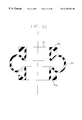
- FIG. 1 is a cross-sectional view of one embodiment of a hose connection constructed in accordance with the present invention
- FIG. 2 is a cross-sectional view of another embodiment of a hose connection constructed in accordance with the present invention.
- FIG. 3 is a cross-sectional view of the embodiment shown in FIG. 2, with a hose connected to a pipe flange;
- FIG. 4 is a cross-sectional view of another embodiment of a connection system in accordance with the present invention.
- FIG. 5 is a cross-sectional view of another embodiment of connection system in accordance with the present invention, incorporating a two-part clamp arrangement;
- FIG. 6 is a cut-away detailed view of the hose reinforcement associated with one embodiment of the present invention.
- FIG. 7 is a cross-sectional view of another embodiment of the present invention.
- FIG. 8 is a cross-sectional view of another embodiment of the present invention.
- FIG. 9 is a cross-sectional view of another embodiment of the present invention.
- FIG. 10 is a cross-sectional view of another embodiment of the present invention.
- FIG. 11 is a cross-sectional view of another embodiment of the present invention.
- FIG. 12 is a cross-sectional view of another embodiment of the present invention.
- FIG. 13 is a cross-sectional view of one embodiment of the present invention wherein the hose is configured as an expansion joint;
- FIG. 14 is a cross-sectional view of another embodiment of the present invention.
- FIG. 15 is a cross-sectional view of another embodiment of the present invention.
- FIG. 16 is a cross-sectional of the present invention with the hose configured as a vehicle air spring
- FIG. 17 is an embodiment of the present invention as it may be configured during the manufacturing process.
- FIG. 18 is a cross-sectional view illustrating use of the invention as an air spring.
- Hose connections which include the unique connection system of this invention are composed preferably of multiple layers of reinforced elastomeric material (e.g. natural or synthetic rubber).
- reinforced elastomeric material e.g. natural or synthetic rubber.
- a preferred reinforcement connection system is shown in my copending application Ser. No. 08/518,620, filed Aug. 23, 1995, incorporated herein by reference.
- Hoses with wedge section terminations can be manufactured by laying up in sequence, referring to FIG. 6, an inner liner 36 , the various layers of reinforcement (e.g., skimmed tire cord oriented at +54 deg 44 minutes 1, and ⁇ 54 deg 44 minutes 2 followed by an environment resistant cover layer 38 , on a cylindrical mandrel 3 (FIG. 17 ).
- extruded wedges 4 a , 4 b , 4 c , 4 d , and 4 e of uncured high durometer rubber are inserted between adjacent edges of the layers of reinforcement.
- Retaining rings 39 c are secured to terminating flanges 5 to control the precise shape of the enlarged wedge sectioned hose ends 8 . See FIG.
- the aformentioned assembly is then cured in a conventional manner by, for example, winding it with nylon ribbon 7 , followed by autoclave curing. Exposed reinforcing cord ends may optionally be vented to atmosphere or vacuum during cure as depicted by vent means 6 .
- the wedge inserts 4 a , 4 b , 4 c , 4 d , and 4 e may be configured to be identical in cross section to facilitate manufacture using a minimal number of prefabricated (i.e., extruded) shapes.
- the wedges are triangular in cross-section.
- the reinforcement near the hose end may incorporate a greater number of plies near the hose end 9 a than in the body of the hose 9 b in order to accommodate wear, stress concentrations, or bending or support loads associated with the clamp system.
- the hose termination of the present invention may be connected to a rigid flange or mounting surface 10 in lieu of being connected to a similar hose.
- the elastomeric hose flange may be perforated to accommodate bolt circle diameters which are small in comparison to the desired wedge cross section and wedge outside diameter.
- FIG. 7 shows a hose-to-rigid flange 10 connection using a small bolt circle diameter to accommodate bolt 41 .
- FIG. 8 shows a hose-to-hose connection using a small bolt circle diameter.
- FIG. 10 shows a hose-to-rigid flange connection which utilizes a supplementary flange 11 to support the hose wedge section.
- FIG. 11 shows a hose-to-rigid flange connection wherein the hose wedge angle is enlarged in order to maximize the strength of the hose termination.
- FIG. 12 shows a hose termination with greater wedge angle and greater strength than the embodiment shown in FIG. 11 .
- FIG. 13 shows a hose 50 with ends 50 a and 50 b in accordance with the present invention, including an expanded section 50 c , which hose is configured as a pipe expansion joint.
- FIG. 14 and FIG. 15 depict embodiments of the present invention which utilize internal spools 12 against which external clamps 42 and 43 , respectively, are tightened in order to achieve a connection and seal for the connection of hoses 38 .
- FIG. 1 Another embodiment of the hose connection assembly illustrated in FIG. 1 is comprised of a liner 36 , various layers of reinforcement 37 , a cover 38 , clamping rings 39 a and 39 b , and bolts 40 .
- the recesses in the clamping rings are shaped to match the clamped wedge-shaped flanges of the two hoses 38 . In this manner a tight seal is created with no metal parts exposed to the fluid carried by the hoses, and the strength of the connection closely approximates the strength of the hose reinforcement itself. Additionally, no elastomer-to-metal chemical bonds are required to secure the hose ends together.
- connection system of the invention is useful in a variety of situations other than for hose connections.
- the connection system is useful in expansion joints and in actuators (e.g., air springs).
- the inflatable member 52 includes a terminal end portion 52 a with wedges therein enabling it to be clamped to frame 60 .
- Member 62 may be secured, for example, to the axle of a vehicle.
- the inflatable member 52 effectively cushions the frame 60 from vertical movement of the axle.
- FIG. 18 the inflatable member 52 is positioned between frame member 63 and member 64 which is attached to the axle of a vehicle.
- a clamp 54 is threaded onto the flange 64 a to secure the terminal end 52 a to member 64 .
- the connection system can also be used in door seals and in aerospace applications.
- the reinforced layers can be elastomeric or rigid.
Landscapes
- Engineering & Computer Science (AREA)
- Mechanical Engineering (AREA)
- Structural Engineering (AREA)
- General Engineering & Computer Science (AREA)
- Civil Engineering (AREA)
- Laminated Bodies (AREA)
- Barrages (AREA)
- Moulds For Moulding Plastics Or The Like (AREA)
- Joining Of Building Structures In Genera (AREA)
- Forms Removed On Construction Sites Or Auxiliary Members Thereof (AREA)
- Protection Of Pipes Against Damage, Friction, And Corrosion (AREA)
- Rigid Pipes And Flexible Pipes (AREA)
- Clamps And Clips (AREA)
- Heating, Cooling, Or Curing Plastics Or The Like In General (AREA)
- Lining Or Joining Of Plastics Or The Like (AREA)
- Diaphragms And Bellows (AREA)
- Mutual Connection Of Rods And Tubes (AREA)
Abstract
Tubular structures are described which are composed of multiple layers of reinforced material. The structures include at least one terminal end portion which includes one or more wedges between adjacent layers of reinforced material. The structures may be, for example, hoses, expansion joints, or actuators (e.g., air springs). The terminal end portions can be readily clamped together to make appropriate connections, or a terminal end portion can be clamped to a desired mounting surface.
Description
This application is a continuation-in-part of my application Ser. No. 08/518,620, filed Aug. 23, 1995, now U.S. Pat. No. 5,709,502.
This invention generally relates to systems for connecting reinforced hoses and similar reinforced elastomeric cylindrical structures to each other or to corresponding support structures or rigid pipe elements.
Hose terminations for large diameter hose (e.g. over 8 inches in diameter) commonly use large heavy metal spools with attached flanges to terminate each end of a hose. Such spool assemblies are typically vulcanized into an enlarged portion of each end of the resective hose. Abrasion or corrosion protection of such metal spools may require a separate rubber lining for the spool piece. Such assemblies are heavy, inflexible, and costly. Conventional rubber flanges overcome the weight, flexibility and cost problems associated with the metal spools but are limited as to service life and maximum operating pressure. This is because such rubber flanges rely directly on the clamping bolts and on flange friction to resist pull-out. Although a rigid ring may be incorporated near the outer diameter of such a design, the resulting shear loads in the elastomer and the tensile loads in the reinforcement are non-uniform, thus limiting the ultimate strength of the conventional design. Additionally, the conventional arrangement with a flat flange may require periodic re-tightening of the clamping bolts in order to maintain a tight seal.
In accordance with the present invention there is provided an enlarged section at the hose end comprised of multiple plies or layers of reinforcement separated by preferably elastomeric wedges integrally vulcanized thereto. In other words, the hose comprises a plurality of layers of reinforced material, and the terminal end of the hose includes wedge means between adjacent layers of the reinforced material. Each such wedge may be rigid or elastomeric, and preferable each wedge has a triangular cross-section. Opposite side surfaces of each wedge are bonded to the adjacent layers of the reinforced material.
A further advantage of this connection system is that it does not rely on friction or chemical bonding to the clamp components to retain the hose within the connection. The present invention, in fact, functions very well even if all components are lubricated prior to assembly. The connection system of the present invention is thus immune to time-dependent slippage of friction surfaces.
The invention is described in more detail hereinafter with reference to the accompanying drawings, wherein like reference characters refer to the same parts throughout the several views in which:
FIG. 1 is a cross-sectional view of one embodiment of a hose connection constructed in accordance with the present invention;
FIG. 2 is a cross-sectional view of another embodiment of a hose connection constructed in accordance with the present invention;
FIG. 3 is a cross-sectional view of the embodiment shown in FIG. 2, with a hose connected to a pipe flange;
FIG. 4 is a cross-sectional view of another embodiment of a connection system in accordance with the present invention;
FIG. 5 is a cross-sectional view of another embodiment of connection system in accordance with the present invention, incorporating a two-part clamp arrangement;
FIG. 6 is a cut-away detailed view of the hose reinforcement associated with one embodiment of the present invention;
FIG. 7 is a cross-sectional view of another embodiment of the present invention;
FIG. 8 is a cross-sectional view of another embodiment of the present invention;
FIG. 9 is a cross-sectional view of another embodiment of the present invention;
FIG. 10 is a cross-sectional view of another embodiment of the present invention;
FIG. 11 is a cross-sectional view of another embodiment of the present invention;
FIG. 12 is a cross-sectional view of another embodiment of the present invention;
FIG. 13 is a cross-sectional view of one embodiment of the present invention wherein the hose is configured as an expansion joint;
FIG. 14 is a cross-sectional view of another embodiment of the present invention;
FIG. 15 is a cross-sectional view of another embodiment of the present invention;
FIG. 16 is a cross-sectional of the present invention with the hose configured as a vehicle air spring;
FIG. 17 is an embodiment of the present invention as it may be configured during the manufacturing process; and
FIG. 18 is a cross-sectional view illustrating use of the invention as an air spring.
Hose connections which include the unique connection system of this invention are composed preferably of multiple layers of reinforced elastomeric material (e.g. natural or synthetic rubber). A preferred reinforcement connection system is shown in my copending application Ser. No. 08/518,620, filed Aug. 23, 1995, incorporated herein by reference.
Hoses with wedge section terminations can be manufactured by laying up in sequence, referring to FIG. 6, an inner liner 36, the various layers of reinforcement (e.g., skimmed tire cord oriented at +54 deg 44 minutes 1, and −54 deg 44 minutes 2 followed by an environment resistant cover layer 38, on a cylindrical mandrel 3 (FIG. 17). During or after building the aforementioned layers, extruded wedges 4 a, 4 b, 4 c, 4 d, and 4 e of uncured high durometer rubber are inserted between adjacent edges of the layers of reinforcement. Retaining rings 39 c are secured to terminating flanges 5 to control the precise shape of the enlarged wedge sectioned hose ends 8. See FIG. 17. The aformentioned assembly is then cured in a conventional manner by, for example, winding it with nylon ribbon 7, followed by autoclave curing. Exposed reinforcing cord ends may optionally be vented to atmosphere or vacuum during cure as depicted by vent means 6.
Referring again to FIG. 6, the wedge inserts 4 a, 4 b, 4 c, 4 d, and 4 e, for example, may be configured to be identical in cross section to facilitate manufacture using a minimal number of prefabricated (i.e., extruded) shapes. Preferably the wedges are triangular in cross-section.
Referring to FIG. 2, the reinforcement near the hose end may incorporate a greater number of plies near the hose end 9 a than in the body of the hose 9 b in order to accommodate wear, stress concentrations, or bending or support loads associated with the clamp system.
Referring to FIG. 3, the hose termination of the present invention may be connected to a rigid flange or mounting surface 10 in lieu of being connected to a similar hose. Referring to FIG. 7, FIG. 8, FIG. 10, and FIG. 11, the elastomeric hose flange may be perforated to accommodate bolt circle diameters which are small in comparison to the desired wedge cross section and wedge outside diameter. FIG. 7 shows a hose-to-rigid flange 10 connection using a small bolt circle diameter to accommodate bolt 41. FIG. 8 shows a hose-to-hose connection using a small bolt circle diameter. FIG. 10 shows a hose-to-rigid flange connection which utilizes a supplementary flange 11 to support the hose wedge section.
FIG. 11 shows a hose-to-rigid flange connection wherein the hose wedge angle is enlarged in order to maximize the strength of the hose termination. FIG. 12 shows a hose termination with greater wedge angle and greater strength than the embodiment shown in FIG. 11.
FIG. 13 shows a hose 50 with ends 50 a and 50 b in accordance with the present invention, including an expanded section 50 c, which hose is configured as a pipe expansion joint. FIG. 14 and FIG. 15 depict embodiments of the present invention which utilize internal spools 12 against which external clamps 42 and 43, respectively, are tightened in order to achieve a connection and seal for the connection of hoses 38.
Another embodiment of the hose connection assembly illustrated in FIG. 1 is comprised of a liner 36, various layers of reinforcement 37, a cover 38, clamping rings 39 a and 39 b, and bolts 40. The recesses in the clamping rings are shaped to match the clamped wedge-shaped flanges of the two hoses 38. In this manner a tight seal is created with no metal parts exposed to the fluid carried by the hoses, and the strength of the connection closely approximates the strength of the hose reinforcement itself. Additionally, no elastomer-to-metal chemical bonds are required to secure the hose ends together.
The connection system of the invention is useful in a variety of situations other than for hose connections. For example, the connection system is useful in expansion joints and in actuators (e.g., air springs). This is illustrated, for example, in FIGS. 16 and 18. In FIG. 16 the inflatable member 52 includes a terminal end portion 52 a with wedges therein enabling it to be clamped to frame 60. Member 62 may be secured, for example, to the axle of a vehicle. The inflatable member 52 effectively cushions the frame 60 from vertical movement of the axle. In FIG. 18 the inflatable member 52 is positioned between frame member 63 and member 64 which is attached to the axle of a vehicle. A clamp 54 is threaded onto the flange 64 a to secure the terminal end 52 a to member 64. The connection system can also be used in door seals and in aerospace applications. Depending upon the desired application, the reinforced layers can be elastomeric or rigid.
Other variants are possible without departing from the scope of this invention.
Claims (9)
1. A tubular structure comprising a plurality of layers of reinforced material and including a terminal end portion, wherein said end portion further includes at least one elastomeric wedge member between separate adjacent layers of said reinforced material; wherein said at least one wedge member includes opposite side surfaces bonded to said adjacent layers.
2. A tubular structure in accordance with claim 1, wherein said at least one wedge member has a triangular cross-section.
3. A tubular structure in accordance with claim 1, wherein said layers of reinforced material comprise elastomeric sheets.
4. A tubular structure in accordance with claim 1, wherein said at least one wedge member comprises a plurality of wedges each of which has a triangular cross-section.
5. A tubular structure in accordance with claim 1, wherein said tubular structure comprises a hose.
6. A tubular structure in accordance with claim 1, wherein said tubular structure comprises an expansion joint.
7. A tubular structure in accordance with claim 1, wherein said tubular structure comprises an air spring.
8. A combination comprising:
(a) a first tubular structure comprising a plurality of layers of reinforced material and including a first terminal end portion, wherein said end portion further includes a first wedge member between separate adjacent layers of said reinforced material;
(b) a second tubular structure comprising a plurality of layers of reinforced material and including a second terminal end portion, wherein said end portion further includes a second wedge member between separate adjacent layers of said reinforced material; and
(c) clamp means surrounding said first and second terminal end portions for holding said end portions together in abutting relationship.
9. A combination comprising:
(a) a tubular structure comprising a plurality of layers of reinforced material and including a terminal end portion, wherein said end portion further includes at least one elastomeric wedge member between separate adjacent layers of said reinforced material; wherein said at least one wedge member includes opposite side surfaces bonded to said adjacent layers;
(b) a mounting surface; and
(c) clamp means surrounding said terminal end portion and fastened to said mounting surface for connecting said end portion to said mounting surface in abutting relationship.
Priority Applications (1)
| Application Number | Priority Date | Filing Date | Title |
|---|---|---|---|
| US09/008,014 US6196763B1 (en) | 1995-08-23 | 1998-01-16 | Connection system for hoses, expansion joints and actuators |
Applications Claiming Priority (2)
| Application Number | Priority Date | Filing Date | Title |
|---|---|---|---|
| US08/518,620 US5709502A (en) | 1995-08-23 | 1995-08-23 | Connection system for reinforced composite structures |
| US09/008,014 US6196763B1 (en) | 1995-08-23 | 1998-01-16 | Connection system for hoses, expansion joints and actuators |
Related Parent Applications (1)
| Application Number | Title | Priority Date | Filing Date |
|---|---|---|---|
| US08/518,620 Continuation-In-Part US5709502A (en) | 1995-08-23 | 1995-08-23 | Connection system for reinforced composite structures |
Publications (1)
| Publication Number | Publication Date |
|---|---|
| US6196763B1 true US6196763B1 (en) | 2001-03-06 |
Family
ID=24064749
Family Applications (3)
| Application Number | Title | Priority Date | Filing Date |
|---|---|---|---|
| US08/518,620 Expired - Lifetime US5709502A (en) | 1995-08-23 | 1995-08-23 | Connection system for reinforced composite structures |
| US09/008,048 Expired - Lifetime US5948501A (en) | 1995-08-23 | 1998-01-16 | Composite to metal structural connection |
| US09/008,014 Expired - Lifetime US6196763B1 (en) | 1995-08-23 | 1998-01-16 | Connection system for hoses, expansion joints and actuators |
Family Applications Before (2)
| Application Number | Title | Priority Date | Filing Date |
|---|---|---|---|
| US08/518,620 Expired - Lifetime US5709502A (en) | 1995-08-23 | 1995-08-23 | Connection system for reinforced composite structures |
| US09/008,048 Expired - Lifetime US5948501A (en) | 1995-08-23 | 1998-01-16 | Composite to metal structural connection |
Country Status (12)
| Country | Link |
|---|---|
| US (3) | US5709502A (en) |
| EP (1) | EP0846205B1 (en) |
| JP (2) | JP3665647B2 (en) |
| KR (2) | KR100600115B1 (en) |
| CN (1) | CN1051127C (en) |
| AT (1) | ATE211204T1 (en) |
| AU (1) | AU717818B2 (en) |
| CA (1) | CA2229213C (en) |
| DE (1) | DE69618209T2 (en) |
| ES (1) | ES2165519T3 (en) |
| IN (1) | IN190515B (en) |
| WO (1) | WO1997008393A1 (en) |
Cited By (5)
| Publication number | Priority date | Publication date | Assignee | Title |
|---|---|---|---|---|
| US20030143027A1 (en) * | 2001-07-09 | 2003-07-31 | Henry K. Obermeyer | Water control gate and actuator therefore |
| US6678937B2 (en) * | 2000-10-26 | 2004-01-20 | Kimball Physics, Inc. | Alternative method for sealing all-metal vacuum joints |
| US20070086854A1 (en) * | 2005-10-18 | 2007-04-19 | General Electric Company | Methods and apparatus for assembling composite structures |
| US20080193201A1 (en) * | 2004-05-03 | 2008-08-14 | Carl Zeiss Smt Ag | Optical Assembly Structure Comprising a Connecting Body with Thermal Expansion Compensations Means |
| US10179282B2 (en) | 2016-02-26 | 2019-01-15 | Impyrium, Inc. | Joystick input apparatus with living hinges |
Families Citing this family (22)
| Publication number | Priority date | Publication date | Assignee | Title |
|---|---|---|---|---|
| WO2001051714A1 (en) * | 2000-01-12 | 2001-07-19 | Akio Iida | Elevating gate |
| GB0127216D0 (en) * | 2001-11-13 | 2002-01-02 | Univ Edinburgh | Watertight gate mechanism |
| EA010821B1 (en) * | 2004-08-31 | 2008-12-30 | Хенри К. Обермейер | High strength joining system for fiber reinforced composites |
| US7422392B2 (en) * | 2004-10-06 | 2008-09-09 | Obermeyer Henry K | Water control structure |
| DE102005056134B4 (en) * | 2005-11-23 | 2007-09-20 | Autoliv Development Ab | security system |
| KR100578256B1 (en) * | 2006-02-02 | 2006-05-11 | 한국기술개발 주식회사 | Movable step for the water level regulation of the rivers |
| KR100865872B1 (en) | 2008-04-24 | 2008-10-29 | 김명진 | Movable floodgate apparatus of riffle type |
| CN102071664B (en) * | 2010-12-16 | 2012-11-21 | 江河机电装备工程有限公司 | Room temperature vulcanizing high-strength seamless large-scale rubber air sac and production technology thereof |
| ITMO20120062A1 (en) | 2012-03-12 | 2013-09-13 | E P Di Provasi Elvino Ambientenerg Ia | PERFECT HYDRAULIC BRIDLE. |
| GB201217245D0 (en) * | 2012-09-27 | 2012-11-07 | Airbus Operations Ltd | A cure tool |
| EP2912228B1 (en) * | 2012-10-23 | 2017-02-01 | Eextreme Global Limited | A retention device |
| CN103074870B (en) * | 2013-01-28 | 2015-04-08 | 曲振会 | Novel rubber dam body |
| US9308704B2 (en) | 2013-02-18 | 2016-04-12 | The Boeing Company | Elastomeric bladder system |
| CN103132490A (en) * | 2013-02-19 | 2013-06-05 | 江河机电装备工程有限公司 | Clamping casting device for 1-4m pneumatic shield-shaped gate |
| GB201310299D0 (en) * | 2013-06-10 | 2013-07-24 | Lee Christopher E | Storm inflatable dam deployment system |
| US20170167096A1 (en) * | 2013-09-23 | 2017-06-15 | Henry Obermeyer | Inflatable Article with Reduced Stress Concentrations |
| US9957681B2 (en) * | 2014-07-18 | 2018-05-01 | Henry K. Obermeyer | Water control gate anchoring system and method |
| CN105714744A (en) * | 2015-06-03 | 2016-06-29 | 浙江海洋学院 | Water stopping dam |
| EP3339513B1 (en) * | 2015-09-25 | 2020-03-25 | Terata, Hiroshi | Sluice gate |
| US10975538B2 (en) | 2016-06-13 | 2021-04-13 | Rsa Protective Technologies, Llc | Method and system for a retractable floodwall system |
| BR112018075818B1 (en) * | 2016-06-13 | 2023-02-14 | Rsa Protective Technologies, Llc | RETRACTABLE AND ENTRY FLOOD WALL UNIT AND FLOOD SHELTER |
| DK179294B1 (en) * | 2017-03-30 | 2018-04-16 | Steen Olsen Invest Aps | Flood protection |
Citations (18)
| Publication number | Priority date | Publication date | Assignee | Title |
|---|---|---|---|---|
| US294160A (en) * | 1884-02-26 | Metallic steam-pipe connection | ||
| US1185487A (en) * | 1915-06-25 | 1916-05-30 | Harold K Eastman | Pipe-coupling. |
| US1939872A (en) * | 1932-10-05 | 1933-12-19 | Goodrich Co B F | Coupling for flexible hose |
| US2201684A (en) * | 1937-09-02 | 1940-05-21 | Gen Ceramics Company | Ceramic article |
| US2408960A (en) * | 1944-07-25 | 1946-10-08 | Whitehead Bros Rubber Company | Flexible pipe coupling |
| US2911236A (en) * | 1956-11-09 | 1959-11-03 | Kleber Colombes | Semi-flexible pipes and pipe connecting means |
| US2919936A (en) * | 1956-01-03 | 1960-01-05 | Curtiss Wright Corp | Metallic lined pipe coupling having a metallic seal |
| US3235291A (en) * | 1963-04-29 | 1966-02-15 | Phillips Petroleum Co | Coupling for a thermoplastic liner in a metal conduit |
| US3563573A (en) * | 1968-04-02 | 1971-02-16 | Dunlop Co Ltd | Pipe assemblies |
| US4023782A (en) * | 1974-09-06 | 1977-05-17 | S.A. Des Anciens Etablissements Paul Wurth | Tuyere stock and compensator joint therefore |
| US4484771A (en) * | 1980-12-18 | 1984-11-27 | Schulz & Company Kg | Flange for connecting pipes |
| US4537003A (en) * | 1982-07-29 | 1985-08-27 | Kober Ag | Elastomeric sectional strip for expansion joints |
| US4649960A (en) * | 1982-04-27 | 1987-03-17 | Hercules Incorporated | Filament wound interlaminate tubular attachment |
| US4747806A (en) * | 1985-01-31 | 1988-05-31 | Uni-Cardan Aktiengesellschaft | Detachable flange connection for torque transmitting drive shaft particularly for connecting two parts of a cardan drive shaft for motor vehicles |
| US4774795A (en) * | 1983-01-31 | 1988-10-04 | Braun Frank A | Expansion joint |
| US4838831A (en) * | 1982-09-30 | 1989-06-13 | The Boeing Company | Coupling for connecting two shafts |
| US4872712A (en) * | 1985-08-31 | 1989-10-10 | Agintec Ag | Flange connection |
| US5716158A (en) * | 1996-08-23 | 1998-02-10 | The Atlantic Group, Inc. | Expandable belt type expansion joint |
Family Cites Families (21)
| Publication number | Priority date | Publication date | Assignee | Title |
|---|---|---|---|---|
| GB572932A (en) * | 1943-06-07 | 1945-10-30 | Anglo Iranian Oil Co Ltd | Improvements relating to couplings for flexible tubes or electric cables |
| GB1091281A (en) * | 1963-06-19 | 1967-11-15 | Dunlop Rubber Co | Improvements in vehicle supporting and propelling members |
| IT972594B (en) * | 1972-12-20 | 1974-05-31 | Pirelli | PNEUMATIC PUCTA |
| AR202245A1 (en) * | 1974-03-04 | 1975-05-23 | Pirelli | PNEUMATIC WHEEL FOR AUTOMOTIVE VEHICLES |
| US3975915A (en) * | 1974-10-23 | 1976-08-24 | The Firestone Tire & Rubber Company | Anchor assembly for an inflatable fabric dam |
| FR2318041A1 (en) * | 1975-07-18 | 1977-02-11 | Uniroyal | PNEUMATIC SAFETY BANDAGE FOR VEHICLE WHEELS AND ITS COMPONENT ELEMENTS |
| US4299514A (en) * | 1978-12-06 | 1981-11-10 | Bridgestone Tire Co., Ltd. | Collapsible rubber dam |
| US4330224A (en) * | 1979-03-20 | 1982-05-18 | Bridgestone Tire Company Limited | Collapsible rubber dam installation |
| US4498810A (en) * | 1980-03-06 | 1985-02-12 | Bridgestone Tire Company Limited | Collapsible rubber dam |
| HU183563B (en) * | 1981-09-03 | 1984-05-28 | Taurus Gumiipari Vallalat | High-pressure hose suitable for carrying gases and gas-containing fluids |
| US4647250A (en) * | 1983-04-22 | 1987-03-03 | Howard Ralph H | Canadian flexible dams |
| GB2184150B (en) * | 1985-10-12 | 1989-11-29 | Bridgestone Corp | Flexible sheet dam |
| JP2688896B2 (en) * | 1987-02-03 | 1997-12-10 | 株式会社ブリヂストン | Damage protection flexible membrane weir |
| US4780024A (en) * | 1987-06-05 | 1988-10-25 | Obermeyer Henry K | Crest gate |
| US4921373A (en) * | 1988-12-07 | 1990-05-01 | Coffey Robert C | Barrier for containing floods |
| JP2717564B2 (en) * | 1989-01-20 | 1998-02-18 | 株式会社ブリヂストン | Rubber dam |
| JP2794216B2 (en) * | 1989-12-28 | 1998-09-03 | 株式会社ブリヂストン | Flexible membrane weir |
| US5092707A (en) * | 1990-10-25 | 1992-03-03 | Obermeyer Henry K | Crest gate operating system |
| US5713699A (en) * | 1992-03-02 | 1998-02-03 | Obermeyer; Henry K. | Spillway crest gate system and inflatable bladder therefor |
| US5538360A (en) * | 1992-03-02 | 1996-07-23 | Obermeyer; Henry K. | Crest gate operating system |
| US5422150A (en) * | 1993-12-23 | 1995-06-06 | Hycomp, Inc. | Substrate clad with fiber-reinforced polymer composite |
-
1995
- 1995-08-23 US US08/518,620 patent/US5709502A/en not_active Expired - Lifetime
-
1996
- 1996-06-14 IN IN1112CA1996 patent/IN190515B/en unknown
- 1996-08-21 WO PCT/US1996/013633 patent/WO1997008393A1/en not_active Application Discontinuation
- 1996-08-21 ES ES96929020T patent/ES2165519T3/en not_active Expired - Lifetime
- 1996-08-21 KR KR1020057001544A patent/KR100600115B1/en not_active IP Right Cessation
- 1996-08-21 AT AT96929020T patent/ATE211204T1/en active
- 1996-08-21 CN CN96197535A patent/CN1051127C/en not_active Expired - Lifetime
- 1996-08-21 CA CA002229213A patent/CA2229213C/en not_active Expired - Lifetime
- 1996-08-21 AU AU68578/96A patent/AU717818B2/en not_active Expired
- 1996-08-21 JP JP51045397A patent/JP3665647B2/en not_active Expired - Lifetime
- 1996-08-21 KR KR1019980701305A patent/KR100557025B1/en not_active IP Right Cessation
- 1996-08-21 EP EP96929020A patent/EP0846205B1/en not_active Expired - Lifetime
- 1996-08-21 DE DE69618209T patent/DE69618209T2/en not_active Expired - Lifetime
-
1998
- 1998-01-16 US US09/008,048 patent/US5948501A/en not_active Expired - Lifetime
- 1998-01-16 US US09/008,014 patent/US6196763B1/en not_active Expired - Lifetime
-
2005
- 2005-01-13 JP JP2005006460A patent/JP3759153B2/en not_active Expired - Lifetime
Patent Citations (18)
| Publication number | Priority date | Publication date | Assignee | Title |
|---|---|---|---|---|
| US294160A (en) * | 1884-02-26 | Metallic steam-pipe connection | ||
| US1185487A (en) * | 1915-06-25 | 1916-05-30 | Harold K Eastman | Pipe-coupling. |
| US1939872A (en) * | 1932-10-05 | 1933-12-19 | Goodrich Co B F | Coupling for flexible hose |
| US2201684A (en) * | 1937-09-02 | 1940-05-21 | Gen Ceramics Company | Ceramic article |
| US2408960A (en) * | 1944-07-25 | 1946-10-08 | Whitehead Bros Rubber Company | Flexible pipe coupling |
| US2919936A (en) * | 1956-01-03 | 1960-01-05 | Curtiss Wright Corp | Metallic lined pipe coupling having a metallic seal |
| US2911236A (en) * | 1956-11-09 | 1959-11-03 | Kleber Colombes | Semi-flexible pipes and pipe connecting means |
| US3235291A (en) * | 1963-04-29 | 1966-02-15 | Phillips Petroleum Co | Coupling for a thermoplastic liner in a metal conduit |
| US3563573A (en) * | 1968-04-02 | 1971-02-16 | Dunlop Co Ltd | Pipe assemblies |
| US4023782A (en) * | 1974-09-06 | 1977-05-17 | S.A. Des Anciens Etablissements Paul Wurth | Tuyere stock and compensator joint therefore |
| US4484771A (en) * | 1980-12-18 | 1984-11-27 | Schulz & Company Kg | Flange for connecting pipes |
| US4649960A (en) * | 1982-04-27 | 1987-03-17 | Hercules Incorporated | Filament wound interlaminate tubular attachment |
| US4537003A (en) * | 1982-07-29 | 1985-08-27 | Kober Ag | Elastomeric sectional strip for expansion joints |
| US4838831A (en) * | 1982-09-30 | 1989-06-13 | The Boeing Company | Coupling for connecting two shafts |
| US4774795A (en) * | 1983-01-31 | 1988-10-04 | Braun Frank A | Expansion joint |
| US4747806A (en) * | 1985-01-31 | 1988-05-31 | Uni-Cardan Aktiengesellschaft | Detachable flange connection for torque transmitting drive shaft particularly for connecting two parts of a cardan drive shaft for motor vehicles |
| US4872712A (en) * | 1985-08-31 | 1989-10-10 | Agintec Ag | Flange connection |
| US5716158A (en) * | 1996-08-23 | 1998-02-10 | The Atlantic Group, Inc. | Expandable belt type expansion joint |
Cited By (15)
| Publication number | Priority date | Publication date | Assignee | Title |
|---|---|---|---|---|
| US7216899B2 (en) | 2000-10-26 | 2007-05-15 | Kimball Physics, Inc. | Alternative method for sealing all-metal vacuum joints |
| US6678937B2 (en) * | 2000-10-26 | 2004-01-20 | Kimball Physics, Inc. | Alternative method for sealing all-metal vacuum joints |
| US20040124636A1 (en) * | 2000-10-26 | 2004-07-01 | Crawford Charles K. | Alternative method for sealing all-metal vacuum joints |
| US20060072969A1 (en) * | 2001-07-09 | 2006-04-06 | Henry K. Obermeyer | Water control apparatus |
| US7114879B2 (en) * | 2001-07-09 | 2006-10-03 | Henry K. Obermeyer | Water control gate and actuator therefore |
| US20030143027A1 (en) * | 2001-07-09 | 2003-07-31 | Henry K. Obermeyer | Water control gate and actuator therefore |
| US20110116871A1 (en) * | 2001-07-09 | 2011-05-19 | Henry K. Obermeyer | Water Control Apparatus |
| US8511937B2 (en) | 2001-07-09 | 2013-08-20 | Henry K. Obermeyer | Water control apparatus |
| US9028170B2 (en) | 2001-07-09 | 2015-05-12 | Henry K. Obermeyer | Water control apparatus |
| US9765495B2 (en) | 2001-07-09 | 2017-09-19 | Henry K. Obermeyer | Water control apparatus |
| US10370813B2 (en) | 2001-07-09 | 2019-08-06 | Henry K. Obermeyer | Water control apparatus |
| US20080193201A1 (en) * | 2004-05-03 | 2008-08-14 | Carl Zeiss Smt Ag | Optical Assembly Structure Comprising a Connecting Body with Thermal Expansion Compensations Means |
| US20070086854A1 (en) * | 2005-10-18 | 2007-04-19 | General Electric Company | Methods and apparatus for assembling composite structures |
| US8079773B2 (en) * | 2005-10-18 | 2011-12-20 | General Electric Company | Methods and apparatus for assembling composite structures |
| US10179282B2 (en) | 2016-02-26 | 2019-01-15 | Impyrium, Inc. | Joystick input apparatus with living hinges |
Also Published As
| Publication number | Publication date |
|---|---|
| ATE211204T1 (en) | 2002-01-15 |
| US5709502A (en) | 1998-01-20 |
| EP0846205A1 (en) | 1998-06-10 |
| ES2165519T3 (en) | 2002-03-16 |
| CN1051127C (en) | 2000-04-05 |
| US5948501A (en) | 1999-09-07 |
| KR100600115B1 (en) | 2006-07-13 |
| KR19990044072A (en) | 1999-06-25 |
| AU717818B2 (en) | 2000-04-06 |
| KR100557025B1 (en) | 2006-06-21 |
| AU6857896A (en) | 1997-03-19 |
| JP3759153B2 (en) | 2006-03-22 |
| DE69618209T2 (en) | 2002-08-22 |
| CA2229213C (en) | 2007-05-22 |
| MX9801412A (en) | 1998-05-31 |
| JP2005098110A (en) | 2005-04-14 |
| DE69618209D1 (en) | 2002-01-31 |
| WO1997008393A1 (en) | 1997-03-06 |
| KR20050044795A (en) | 2005-05-12 |
| CA2229213A1 (en) | 1997-03-06 |
| CN1199441A (en) | 1998-11-18 |
| JP3665647B2 (en) | 2005-06-29 |
| JPH11511523A (en) | 1999-10-05 |
| EP0846205B1 (en) | 2001-12-19 |
| IN190515B (en) | 2003-08-02 |
Similar Documents
| Publication | Publication Date | Title |
|---|---|---|
| US6196763B1 (en) | Connection system for hoses, expansion joints and actuators | |
| US5028056A (en) | Fiber composite sealing element | |
| US3680895A (en) | Flexible joint means | |
| US6000435A (en) | Reinforced hose and retainer ring assembly | |
| US10603956B2 (en) | Wheel for a support structure | |
| CA1128433A (en) | Lug bead hose | |
| AU8787398A (en) | Interface system between composite tubing and end fittings | |
| US6830076B1 (en) | Self-compensating hybrid combination ducts | |
| CA2117401A1 (en) | Gasket for a pipe joint | |
| EP2041465B1 (en) | Apparatus, system, and method for joining and sealing conduits | |
| JPH0629588Y2 (en) | Flexible connection device | |
| US3796449A (en) | Reinforced flange for plastic pipe | |
| US4768563A (en) | Quick-disconnect hose | |
| US4366842A (en) | Flanged hose and method of making | |
| US6508714B1 (en) | Split spool type flexible coupling | |
| US5004513A (en) | Method for forming a fiber composite sealing element | |
| US4240653A (en) | Flexible expansion joint | |
| JPH03236946A (en) | Manufacturer of fiber reinforced cylinder tube | |
| US4303102A (en) | Hose ending and method of forming same | |
| JPS5838176Y2 (en) | Kuukibane | |
| JP3981419B2 (en) | Embedded flexible joint and manufacturing method thereof | |
| JP2001205707A (en) | Flanged fiber reinforced resin pipe | |
| GB2159224A (en) | Flexible joint | |
| JPH0643596Y2 (en) | Flexible joint flange structure | |
| JPS6364298B2 (en) |
Legal Events
| Date | Code | Title | Description |
|---|---|---|---|
| STCF | Information on status: patent grant |
Free format text: PATENTED CASE |
|
| FPAY | Fee payment |
Year of fee payment: 4 |
|
| FPAY | Fee payment |
Year of fee payment: 8 |
|
| AS | Assignment |
Owner name: POINTS WEST COMMUNITY BANK, COLORADO Free format text: SECURITY AGREEMENT;ASSIGNOR:OBERMEYER, HENRY K;REEL/FRAME:024964/0883 Effective date: 20100910 |
|
| FPAY | Fee payment |
Year of fee payment: 12 |