EP0153554A2 - Verschlussdüsenvorrichtung zum Spritzgiessen - Google Patents
Verschlussdüsenvorrichtung zum Spritzgiessen Download PDFInfo
- Publication number
- EP0153554A2 EP0153554A2 EP85100153A EP85100153A EP0153554A2 EP 0153554 A2 EP0153554 A2 EP 0153554A2 EP 85100153 A EP85100153 A EP 85100153A EP 85100153 A EP85100153 A EP 85100153A EP 0153554 A2 EP0153554 A2 EP 0153554A2
- Authority
- EP
- European Patent Office
- Prior art keywords
- nose portion
- gate
- cavity
- cavity plate
- nozzle
- Prior art date
- Legal status (The legal status is an assumption and is not a legal conclusion. Google has not performed a legal analysis and makes no representation as to the accuracy of the status listed.)
- Granted
Links
Images
Classifications
-
- B—PERFORMING OPERATIONS; TRANSPORTING
- B29—WORKING OF PLASTICS; WORKING OF SUBSTANCES IN A PLASTIC STATE IN GENERAL
- B29C—SHAPING OR JOINING OF PLASTICS; SHAPING OF MATERIAL IN A PLASTIC STATE, NOT OTHERWISE PROVIDED FOR; AFTER-TREATMENT OF THE SHAPED PRODUCTS, e.g. REPAIRING
- B29C45/00—Injection moulding, i.e. forcing the required volume of moulding material through a nozzle into a closed mould; Apparatus therefor
- B29C45/17—Component parts, details or accessories; Auxiliary operations
- B29C45/26—Moulds
- B29C45/27—Sprue channels ; Runner channels or runner nozzles
- B29C45/28—Closure devices therefor
- B29C45/2806—Closure devices therefor consisting of needle valve systems
- B29C2045/2848—Closure devices therefor consisting of needle valve systems having an adjustable stroke length
-
- Y—GENERAL TAGGING OF NEW TECHNOLOGICAL DEVELOPMENTS; GENERAL TAGGING OF CROSS-SECTIONAL TECHNOLOGIES SPANNING OVER SEVERAL SECTIONS OF THE IPC; TECHNICAL SUBJECTS COVERED BY FORMER USPC CROSS-REFERENCE ART COLLECTIONS [XRACs] AND DIGESTS
- Y10—TECHNICAL SUBJECTS COVERED BY FORMER USPC
- Y10S—TECHNICAL SUBJECTS COVERED BY FORMER USPC CROSS-REFERENCE ART COLLECTIONS [XRACs] AND DIGESTS
- Y10S425/00—Plastic article or earthenware shaping or treating: apparatus
- Y10S425/227—Injection nozzle; positioned flush with mold or cavity
Definitions
- This invention relates to valve gated injection molding and more particularly to an improved system in which the heated nozzle has a nose portion which extends through an opening in the cavity plate directly to the cavity and itself forms the gate in which the tip end of the valve pin seats to control the flow of melt to the cavity.
- this type of injection molding sytem has an insulative air space extending between the heated nozzle and the cooled cavity plate. In many early applications, this space was allowed to fill with melt which partially solidified and acted as an insulator. However, this has the disadvantage that it is difficult, if not impossible, to clear the previous material on colour and/or material changes, and furthermore for some materials additional heat is required in the gate area to ensure satisfactory seating of the valve pin in the gate.
- a hollow cylindrical nozzle seal formed of titanium as described in the applicant's U.S. Patent No. 4,043,740 which issued August 23, 1977. This seal is seated in both the nozzle and cavity plate to bridge the air space around the gate. More recently, as described in the applicant's U.S. Patent No. 4,286,941 which issued September 1, 1981, a titanium nozzle seal has been provided which extends through an opening in the cavity plate right into the cavity to provide even more heat in the gate area adjacent the cavity. While these previous systems have been very successful, they have the disadvantages that a particular unit has to be used for a particular gate size and the moldmaker has to be very precise in making the gate the correct size and the correct angle.
- the nozzle can be adapted for a particular gate size by machining off a portion of the nose portion.
- the invention provides a valve gated injection molding system having a heated nozzle seated in a cooled cavity plate, an elongated valve pin which reciprocates in the heated nozzle between open and closed positions, a melt passage which extends through a bore in the heated nozzle around the valve pin and conveys hot pressurized melt from a molding machine to a gate leading to a cavity which is partially defined on one side by a face of the cavity plate, the valve pin having a driven end and a tip end which seats in the gate in the closed position, and valve pin actuating mechanism which engages the driven end of the valve pin to drive it between the open and closed positions, including the improvement wherein the heated nozzle has a nose portion with a forward face, the nose portion being tightly seated in.an opening in the cavity plate to the cavity, the nose portion extending through the opening to a position wherein the forward face of the nozzle portion is in substantial alignment with said face of the cavity plate to define said one side of the cavity, the nose portion having the gate therein
- the nose portion of the heated nozzle is formed with at least a portion of the gate tapered to decrease in size away from the bore, whereby a predetermined portion of the nose portion may be machined off prior to assembly to increase the minimum size of the gate at the forward face of the nose portion to a particular cross-sectional area and to reduce the length of the nose portion.
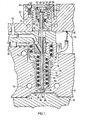
- FIG. 1 shows one heated nozzle 10 of a multi-cavity hydraulically actuated valve gated injection molding system seated in a steel cavity plate 12 with a cavity 14 extending between the cavity plate 12 and a movable mold platen 16.
- a manifold 18 positioned by locating ring 20 extends between the heated nozzle 10 and cavity plate 12 and a back plate 22.
- the heated nozzle 10 is formed generally of a corrosion and abrasion resistant metal such as steel, but has an electric heating element 24 cast into an inner portion 26 formed of a highly thermally conductive metal such as copper to more rapidly disperse the heat to the steel.
- the heated nozzle 10 has a central bore 28 which receives an elongated valve pin 30 having a driven end 32 and a tip end 34.
- the driven end 32 of the valve -pin 30 is engaged by hydraulically driven actuating mechanism which is seated in the back plate 22 and reciprocates the valve pin longitudinally between the open position shown and a closed position in which the tip end 34 is seated in a gate 36 leading to the cavity 14.
- the actuating mechanism includes a piston 38 which reciprocates in a cylinder 40 seated in a bore in the back plate 22.
- the cylinder 40 is secured in position by bolts 42 extending through a flanged portion 44.
- the cylinder is sealed by a cap 46 which is screwed into the cylinder 40 and tightened by a forked wrench (not shown) which has pins that fit into the small holes 48 in the top of the cap 46.
- the valve pin 30 extends through a hole in the piston 38 and is secured to it by a plug 50 which is tightened against the driven end 32 of the piston by inserting a hexagonal wrench (not shown) into a socket 52.
- the piston 38 has an O-ring 54 which provides a seal between it and the cylinder, and a high temperature seal is provided around the neck 56 of the piston 38 by a V-shaped flexible ring 58 which is held in position by an expansion washer 60 seated in a groove.
- An abutment sleeve 62 is located between the piston 38 and the cap 46 so that the extent of travel of the piston 38 and the valve pin 30 in the open position can be adjusted by changing the height of the abutment sleeve 62.
- a melt passage 68 branches out from a recessed inlet 70 through the manifold 18 and extends around the valve pin 30 through the bore 28 in the heated nozzle 10 to the gate 36.
- the melt passage 68 joins the bore 28 in a stainless steel bushing seal 72 which is seated in the nozzle 10.
- the bushing seal prevents leakage of the pressurized melt along the reciprocating valve pin 30.
- the cavity plate 12 and back plate 22 are cooled in a conventional manner by cooling channels 74.
- the nozzle 10 is heated by the insulated electrical element 24 which is cast into it and receives power through terminals 76 (only one shown) to maintain the melt flowing through the melt passage 68 within the necessary temperature range.
- the heated nozzle 10 is seated in the cavity plate 12 on an insulation bushing 78 which provides an insulative air space 80 between the hot nozzle and the cool cavity plate.
- the locating ring 20 separates the hot manifold 18 from the cool cavity plate to ensure the insulative air space 80 continues between them.
- a second insulative air space 82 extends between the cool back plate 22 and the hot manifold 18.
- the heated nozzle 10 has a cylindrical shaped nose portion 84 through which the gate 36 extends to the cavity 14.
- the nose portion 84 is securely seated in a cylindrical opening 86 through the cavity plate 12 and has a forward face 88 which, at working temperature, is in alignment with the face 90 of the cavity plate 12 which partially defines the cavity 14.
- this arrangment has the advantage for critical temperature materials such as polyester and also very high and sharp melting point materials that a more uniform temperature is provided right into the cavity. In other words, improved heat transfer is provided to the gate area and it is not necessary to overheat the melt in the area of the heating element 24 to avoid too low a temperature adjacent the cavity.
- critical temperature materials such as polyester and also very high and sharp melting point materials that a more uniform temperature is provided right into the cavity.
- improved heat transfer is provided to the gate area and it is not necessary to overheat the melt in the area of the heating element 24 to avoid too low a temperature adjacent the cavity.
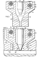
- FIG. 2 shows the nose portion 84 and the valve pin tip end 34 as they are supplied by the manufacturer prior to installation.
- the moldmaker then machines the nose portion to a particular length corresponding to one of the dotted lines shown in Figure 2 which provides the gate with a selected minimum size at the forward face 88 due to the fact that the gate 36 is tapered in the area.
- the manufacturer provides the moldmaker with a chart showing the nozzle length to which the nose portion must be machined to provide minimum gate diameters of say 1.5 mm, 2.0 mm, 2.5 mm or 3.0 mm.
- the tip end 34 of the valve pin 30 must similarly be machined to a selected length to correspond to the minimum gate diameter as indicated by the dotted lines in Figure 2.
- the tip end 34 of the valve pin 30 is tapered to match the taper of the gate 36 to provide a tight seal in the closed position.
- both of these are formed by the manufacturer and the gate is normally lapped to provide a good match.
- the moldmaker has the much easier task of providing cylindrical opening 86 through the cavity plate rather than forming a tapered gate of a particular size to match a particular valve pin.
- the moldmaker machines the nose portions 84 of the nozzles and the tip ends 34 of the valve pins 30 to provide gates of a particular size, and the system is assembled as shown in Figure 1.
- the cylindrical opening 86 in the cavity plate 12 is made to receive the nose portion 84 of the nozzle 10 when it is cool so that it expands to provide a tight press fit when the nozzle is heated to operating temperature.
- the amount of heat in the gate area may also be increased by the moldmaker reducing the length of contact H between the cooled cavity plate 12 and the nose portion 84 of the heated nozzle 10. This will depend upon the material to be molded; for instance H might be about 2 mm for nylon and about 4 mm for PVC or ABS.
- the insulation bushing 78 be machined to provide for substantial alignment of the forward face 88 of the nose portion 84 with the adjacent cavity face 90 of the cavity plate after heat expansion at operating temperature. Similarly, the height of the locating ring 20 is adjusted to accurately position the manifold 18 against the nozzle 10.
- the forward face 88 of the nose portion 84 and the adjacent face 90 of the cavity plate 12 form one side of the cavity 14, and therefore it is important that the fit between them be tight to provide the desired temperature in the gate, minimize the witness line on the product, as well as, of course, to avoid leakage.
- Figure 3 shows an alternate embodiment of the invnetion in which the nose portion 84 of the heated nozzle 10 has a somewhat different configuration.
- the nose portion 84 is undercut to provide it iwth a cylindrical shaped head portion 92 extending from a reduced diameter neck portion 94 to the forward face 88. This extends the air space 80 down around the reduced neck portion 94 and reduces heat loss to the cavity plate 12 and also enhance heat transfer to the gate area.
- this undercut configuration may be used in addition to or instead of increasing height H for materials where less heat is required or can be tolerated at the forward face 88. Otherwise, the structure and operation of this embodiment of the invention is the same as that described above, and the description need not be repeated.
Landscapes
- Engineering & Computer Science (AREA)
- Manufacturing & Machinery (AREA)
- Mechanical Engineering (AREA)
- Moulds For Moulding Plastics Or The Like (AREA)
- Injection Moulding Of Plastics Or The Like (AREA)
Priority Applications (1)
| Application Number | Priority Date | Filing Date | Title |
|---|---|---|---|
| AT85100153T ATE53334T1 (de) | 1984-02-17 | 1985-01-09 | Verschlussduesenvorrichtung zum spritzgiessen. |
Applications Claiming Priority (2)
| Application Number | Priority Date | Filing Date | Title |
|---|---|---|---|
| CA447741 | 1984-02-17 | ||
| CA000447741A CA1213706A (en) | 1984-02-17 | 1984-02-17 | Injection molding valve gated system |
Publications (3)
| Publication Number | Publication Date |
|---|---|
| EP0153554A2 true EP0153554A2 (de) | 1985-09-04 |
| EP0153554A3 EP0153554A3 (en) | 1987-10-21 |
| EP0153554B1 EP0153554B1 (de) | 1990-06-06 |
Family
ID=4127230
Family Applications (1)
| Application Number | Title | Priority Date | Filing Date |
|---|---|---|---|
| EP85100153A Expired - Lifetime EP0153554B1 (de) | 1984-02-17 | 1985-01-09 | Verschlussdüsenvorrichtung zum Spritzgiessen |
Country Status (6)
| Country | Link |
|---|---|
| US (1) | US4579520A (de) |
| EP (1) | EP0153554B1 (de) |
| JP (1) | JPS60187458A (de) |
| AT (1) | ATE53334T1 (de) |
| CA (1) | CA1213706A (de) |
| DE (1) | DE3578052D1 (de) |
Cited By (4)
| Publication number | Priority date | Publication date | Assignee | Title |
|---|---|---|---|---|
| GB2186228A (en) * | 1986-01-28 | 1987-08-12 | Leonard Law | Moulding nozzles |
| EP0818295A1 (de) * | 1996-07-10 | 1998-01-14 | Lederer GmbH | Nadelverschlussdüsensystem für ein Kunststoff-Spritzgiesswerkzeug, insbesondere zur Verarbeitung von Silikonkautschuken |
| EP3195998A1 (de) * | 2012-08-08 | 2017-07-26 | Synventive Molding Solutions, Inc. | Strömungssteuerungsvorrichtung und -verfahren |
| US11065794B2 (en) | 2010-11-23 | 2021-07-20 | Synventive Molding Solutions, Inc. | Injection molding flow control apparatus and method |
Families Citing this family (26)
| Publication number | Priority date | Publication date | Assignee | Title |
|---|---|---|---|---|
| CA1238161A (en) * | 1985-12-02 | 1988-06-21 | Jobst U. Gellert | Manufacturing method for selected gate configuration injection molding nozzles |
| US5141696A (en) * | 1986-06-30 | 1992-08-25 | Osuna Diaz J M | Method for injection molding using flow adjusting arrangement |
| CA1252972A (en) * | 1986-10-30 | 1989-04-25 | Harald H. Schmidt | Dual feed single cavity injection molding system |
| CA1252973A (en) * | 1986-12-01 | 1989-04-25 | Harald H. Schmidt | Side mounted manifold block for variable orientation of injection molding nozzle |
| US4808106A (en) * | 1987-11-19 | 1989-02-28 | Holdt J W Von | Flex gate |
| CA1266359A (en) * | 1988-04-13 | 1990-03-06 | Harald H. Schmidt | Injection molding system with nozzles in tandem |
| US4938681A (en) * | 1989-01-03 | 1990-07-03 | Gellert Jobst U | Injection molding system having offset valve pin biasing mechanism |
| US4931009A (en) * | 1989-06-12 | 1990-06-05 | Gellert Jobst U | Injection molding system having a thermal locating flange |
| JPH0524077A (ja) * | 1991-07-18 | 1993-02-02 | Meisei Kinzoku Kogyosho:Kk | ダイレクト・モールデイング |
| JP2636988B2 (ja) * | 1991-09-02 | 1997-08-06 | 大宝工業 株式会社 | 気体圧送金型 |
| CA2180603A1 (en) * | 1996-07-05 | 1998-01-06 | Jobst Ulrich Gellert | Injection molding manifolds with melt connector bushing |
| US6464909B1 (en) | 1998-04-21 | 2002-10-15 | Synventive Molding Solutions, Inc. | Manifold system having flow control |
| US20020121713A1 (en) * | 1997-06-13 | 2002-09-05 | Mark Moss | Apparatus and method for proportionally controlling fluid delivery to stacked molds |
| US20020086086A1 (en) * | 1999-09-21 | 2002-07-04 | Mark Doyle | Curvilinear valve pin controller for injection molding |
| US6228303B1 (en) | 1998-11-13 | 2001-05-08 | Semco Plastics Company, Inc. | Disappearing gate tab |
| AU6416001A (en) * | 2000-06-16 | 2001-12-24 | Mold-Masters Limited | Method for fast manufacturing and assembling of hot runner systems |
| US6675055B1 (en) * | 2000-06-16 | 2004-01-06 | Mold Masters Ltd. | Method and apparatus for an automated injection molding configuring and manufacturing system |
| JP2003103582A (ja) * | 2001-09-28 | 2003-04-09 | Mitsubishi Materials Corp | 射出成形金型 |
| JP2005516794A (ja) * | 2002-02-04 | 2005-06-09 | モールド‐マスターズ、リミテッド | マニホールドとノズルとの間の熱シール |
| US7172411B2 (en) * | 2003-06-20 | 2007-02-06 | Mold-Masters Limited | Injection molding manifold with multi-axis adjustable manifold blocks and nozzles |
| JP4588527B2 (ja) * | 2005-05-10 | 2010-12-01 | 株式会社ブリヂストン | Oaブレード用金型、この金型を用いて形成されたoaブレード、および、このoaブレードを形成するoaブレードの製造方法 |
| JP2007021502A (ja) * | 2005-07-12 | 2007-02-01 | Coki Engineering Inc | 射出成形用のホットランナ金型装置および金属粉末の射出成形方法 |
| US9272455B2 (en) | 2014-04-30 | 2016-03-01 | Mold-Masters (2007) Limited | Hot runner system sealing arrangement |
| DE202015106658U1 (de) * | 2014-12-10 | 2016-01-18 | Inglass S.P.A. | Injektor für Vorrichtungen zum Spritzgießen von Kunststoff |
| CA3021715A1 (en) * | 2016-04-22 | 2017-10-26 | Universal Smart Inc. | Injection molding apparatus and method of use |
| US11878453B2 (en) * | 2019-07-21 | 2024-01-23 | Incoe Corporation | Leak protection bushing for hotrunner manifold assembly |
Family Cites Families (13)
| Publication number | Priority date | Publication date | Assignee | Title |
|---|---|---|---|---|
| US3145421A (en) * | 1961-12-27 | 1964-08-25 | Lee J Colbert | Cable splicing device |
| US3076225A (en) * | 1962-01-05 | 1963-02-05 | William A Sherbondy | Calking gun |
| US3211347A (en) * | 1964-04-14 | 1965-10-12 | Jr Monroe E Phillips | Caulking compound cartridge |
| FR1605509A (en) * | 1968-05-13 | 1978-02-24 | Plastics injection nozzle | |
| DE2316281A1 (de) * | 1973-03-31 | 1974-10-17 | Diamond Tool & Die Co | Spritzbuchse zum einfuehren von kunststoff in eine hohlform |
| CA1029162A (en) * | 1975-04-10 | 1978-04-11 | Jobst U. Gellert | Bushing seal for valve-gated injection mold |
| US4095931A (en) * | 1975-12-01 | 1978-06-20 | Incoe Corporation | Injection molding machine and method |
| CA1067660A (en) * | 1976-03-25 | 1979-12-11 | Jobst U. Gellert | Injection molding nozzle seal |
| CA1136815A (en) * | 1980-07-15 | 1982-12-07 | Jobst U. Gellert | Injection molding nozzle seal |
| US4333608A (en) * | 1980-09-19 | 1982-06-08 | Ex-Cell-O Corporation | Injection molding nozzle |
| CA1165525A (en) * | 1981-02-12 | 1984-04-17 | Jobst U. Gellert | Heated nozzle bushing with fixed spiral blade |
| NL8100791A (nl) * | 1981-02-18 | 1982-09-16 | Anthonie Van Den Brink | Afsluitsysteem. |
| CA1193818A (en) * | 1983-03-24 | 1985-09-24 | Jobst U. Gellert | Hydraulically actuated injection molding system with alternate hydraulic connections |
-
1984
- 1984-02-17 CA CA000447741A patent/CA1213706A/en not_active Expired
- 1984-03-02 US US06/585,835 patent/US4579520A/en not_active Expired - Lifetime
-
1985
- 1985-01-09 DE DE8585100153T patent/DE3578052D1/de not_active Expired - Lifetime
- 1985-01-09 EP EP85100153A patent/EP0153554B1/de not_active Expired - Lifetime
- 1985-01-09 AT AT85100153T patent/ATE53334T1/de not_active IP Right Cessation
- 1985-02-18 JP JP60030138A patent/JPS60187458A/ja active Granted
Cited By (10)
| Publication number | Priority date | Publication date | Assignee | Title |
|---|---|---|---|---|
| GB2186228A (en) * | 1986-01-28 | 1987-08-12 | Leonard Law | Moulding nozzles |
| GB2186228B (en) * | 1986-01-28 | 1989-11-01 | Leonard Law | Moulding nozzles |
| EP0818295A1 (de) * | 1996-07-10 | 1998-01-14 | Lederer GmbH | Nadelverschlussdüsensystem für ein Kunststoff-Spritzgiesswerkzeug, insbesondere zur Verarbeitung von Silikonkautschuken |
| US10307951B2 (en) | 2010-11-23 | 2019-06-04 | Synventive Molding Solutions, Inc. | Injection molding flow control apparatus and method |
| US10625456B2 (en) | 2010-11-23 | 2020-04-21 | Synventive Molding Solutions, Inc. | Injection molding flow control apparatus and method |
| US11065794B2 (en) | 2010-11-23 | 2021-07-20 | Synventive Molding Solutions, Inc. | Injection molding flow control apparatus and method |
| US11065793B2 (en) | 2010-11-23 | 2021-07-20 | Synventive Molding Solutions, Inc. | Injection molding flow control apparatus and method |
| EP3195998A1 (de) * | 2012-08-08 | 2017-07-26 | Synventive Molding Solutions, Inc. | Strömungssteuerungsvorrichtung und -verfahren |
| US9908273B2 (en) | 2012-08-08 | 2018-03-06 | Synventive Molding Solutions, Inc. | Flow control apparatus and method |
| EP3513943A1 (de) * | 2012-08-08 | 2019-07-24 | Synventive Molding Solutions, Inc. | Strömungssteuerungsvorrichtung und -verfahren |
Also Published As
| Publication number | Publication date |
|---|---|
| JPS60187458A (ja) | 1985-09-24 |
| EP0153554A3 (en) | 1987-10-21 |
| EP0153554B1 (de) | 1990-06-06 |
| ATE53334T1 (de) | 1990-06-15 |
| CA1213706A (en) | 1986-11-12 |
| JPH0236348B2 (de) | 1990-08-16 |
| DE3578052D1 (de) | 1990-07-12 |
| US4579520A (en) | 1986-04-01 |
Similar Documents
| Publication | Publication Date | Title |
|---|---|---|
| US4579520A (en) | Injection molding valve gated system | |
| US4530654A (en) | Injection molding peripheral opening core ring gate | |
| EP0270766B1 (de) | Flüssigkeitsgekühlter hydraulischer Antriebsmechanismus zum Spritzgiessen | |
| EP0312098B1 (de) | Spritzgiesssystem mit eingespannten drehbaren Düsen und Verfahren | |
| EP0264724B1 (de) | Mechanismus zum Spritzgiessen mit Verschlussdüsen-Anguss mit einem elastischen Haltering | |
| EP0099088B1 (de) | Spritzgiessnadelverschlussbuchse und ihr Herstellungsverfahren | |
| US4702689A (en) | Side mounted manifold block for variable orientation of injection molding nozzle | |
| US4586887A (en) | Injection molding nozzle probe and stack molding apparatus | |
| US4663811A (en) | Manufacturing method for selected gate configuration injection molding nozzles | |
| EP0200048B1 (de) | Als Ventil ausgebildeter Torpedo | |
| US4740151A (en) | Sealing and retaining bushing for injection molding | |
| EP0120412B1 (de) | Hydraulisch zu betätigende Spritzgusseinrichtung mit wechselweisen hydraulischen Anschlüssen | |
| EP0117510B1 (de) | Ringenverschlusseinrichtung für Spritzgusswerkzeuge | |
| US5049062A (en) | Injection molding system having spring biased nozzles | |
| EP0264725B1 (de) | Zweifache Zuführhülse zum Spritzgiessen mit mehreren Formhöhlungen | |
| EP0405007B1 (de) | Spritzgiesssystem mit einer Buchse mit doppelter Zufuhr, montiert im Verteilerkanal | |
| US4755131A (en) | Fluid cooled hydraulic actuating mechanism for single cavity injection molding | |
| US4836766A (en) | Injection molding valve gating one of two nozzles in tandem | |
| EP0265731B1 (de) | Spritzgiesssystem mit zweifacher Zuführung für eine einzige Formhöhlung | |
| EP0106980A1 (de) | Verschlussdüse zum Spritzgiessen |
Legal Events
| Date | Code | Title | Description |
|---|---|---|---|
| PUAI | Public reference made under article 153(3) epc to a published international application that has entered the european phase |
Free format text: ORIGINAL CODE: 0009012 |
|
| AK | Designated contracting states |
Designated state(s): AT BE CH DE FR GB IT LI LU NL SE |
|
| PUAL | Search report despatched |
Free format text: ORIGINAL CODE: 0009013 |
|
| AK | Designated contracting states |
Kind code of ref document: A3 Designated state(s): AT BE CH DE FR GB IT LI LU NL SE |
|
| 17P | Request for examination filed |
Effective date: 19871202 |
|
| 17Q | First examination report despatched |
Effective date: 19880301 |
|
| ITF | It: translation for a ep patent filed | ||
| GRAA | (expected) grant |
Free format text: ORIGINAL CODE: 0009210 |
|
| AK | Designated contracting states |
Kind code of ref document: B1 Designated state(s): AT BE CH DE FR GB IT LI LU NL SE |
|
| REF | Corresponds to: |
Ref document number: 53334 Country of ref document: AT Date of ref document: 19900615 Kind code of ref document: T |
|
| REF | Corresponds to: |
Ref document number: 3578052 Country of ref document: DE Date of ref document: 19900712 |
|
| ET | Fr: translation filed | ||
| ITTA | It: last paid annual fee | ||
| PLBE | No opposition filed within time limit |
Free format text: ORIGINAL CODE: 0009261 |
|
| STAA | Information on the status of an ep patent application or granted ep patent |
Free format text: STATUS: NO OPPOSITION FILED WITHIN TIME LIMIT |
|
| 26N | No opposition filed | ||
| PGFP | Annual fee paid to national office [announced via postgrant information from national office to epo] |
Ref country code: GB Payment date: 19930104 Year of fee payment: 9 |
|
| PGFP | Annual fee paid to national office [announced via postgrant information from national office to epo] |
Ref country code: FR Payment date: 19930111 Year of fee payment: 9 |
|
| PGFP | Annual fee paid to national office [announced via postgrant information from national office to epo] |
Ref country code: AT Payment date: 19930113 Year of fee payment: 9 |
|
| PGFP | Annual fee paid to national office [announced via postgrant information from national office to epo] |
Ref country code: SE Payment date: 19930115 Year of fee payment: 9 Ref country code: DE Payment date: 19930115 Year of fee payment: 9 |
|
| PGFP | Annual fee paid to national office [announced via postgrant information from national office to epo] |
Ref country code: CH Payment date: 19930118 Year of fee payment: 9 |
|
| PGFP | Annual fee paid to national office [announced via postgrant information from national office to epo] |
Ref country code: NL Payment date: 19930131 Year of fee payment: 9 |
|
| PGFP | Annual fee paid to national office [announced via postgrant information from national office to epo] |
Ref country code: BE Payment date: 19930212 Year of fee payment: 9 |
|
| PGFP | Annual fee paid to national office [announced via postgrant information from national office to epo] |
Ref country code: LU Payment date: 19930217 Year of fee payment: 9 |
|
| EPTA | Lu: last paid annual fee | ||
| PG25 | Lapsed in a contracting state [announced via postgrant information from national office to epo] |
Ref country code: LU Free format text: LAPSE BECAUSE OF NON-PAYMENT OF DUE FEES Effective date: 19940109 Ref country code: GB Effective date: 19940109 Ref country code: AT Effective date: 19940109 |
|
| PG25 | Lapsed in a contracting state [announced via postgrant information from national office to epo] |
Ref country code: SE Effective date: 19940110 |
|
| PG25 | Lapsed in a contracting state [announced via postgrant information from national office to epo] |
Ref country code: LI Effective date: 19940131 Ref country code: CH Effective date: 19940131 Ref country code: BE Effective date: 19940131 |
|
| BERE | Be: lapsed |
Owner name: GELLERT JOBST ULRICH Effective date: 19940131 |
|
| PG25 | Lapsed in a contracting state [announced via postgrant information from national office to epo] |
Ref country code: NL Effective date: 19940801 |
|
| GBPC | Gb: european patent ceased through non-payment of renewal fee |
Effective date: 19940109 |
|
| NLV4 | Nl: lapsed or anulled due to non-payment of the annual fee | ||
| PG25 | Lapsed in a contracting state [announced via postgrant information from national office to epo] |
Ref country code: FR Effective date: 19940930 |
|
| REG | Reference to a national code |
Ref country code: CH Ref legal event code: PL |
|
| PG25 | Lapsed in a contracting state [announced via postgrant information from national office to epo] |
Ref country code: DE Effective date: 19941001 |
|
| REG | Reference to a national code |
Ref country code: FR Ref legal event code: ST |
|
| EUG | Se: european patent has lapsed |
Ref document number: 85100153.7 Effective date: 19940810 |