EP0152844B1 - Düse zum Heissabschlaggranulieren von thermoplastischen Polymeren - Google Patents
Düse zum Heissabschlaggranulieren von thermoplastischen Polymeren Download PDFInfo
- Publication number
- EP0152844B1 EP0152844B1 EP85101080A EP85101080A EP0152844B1 EP 0152844 B1 EP0152844 B1 EP 0152844B1 EP 85101080 A EP85101080 A EP 85101080A EP 85101080 A EP85101080 A EP 85101080A EP 0152844 B1 EP0152844 B1 EP 0152844B1
- Authority
- EP
- European Patent Office
- Prior art keywords
- die
- nozzles
- die according
- plate
- bored
- Prior art date
- Legal status (The legal status is an assumption and is not a legal conclusion. Google has not performed a legal analysis and makes no representation as to the accuracy of the status listed.)
- Expired
Links
Images
Classifications
-
- B—PERFORMING OPERATIONS; TRANSPORTING
- B29—WORKING OF PLASTICS; WORKING OF SUBSTANCES IN A PLASTIC STATE IN GENERAL
- B29B—PREPARATION OR PRETREATMENT OF THE MATERIAL TO BE SHAPED; MAKING GRANULES OR PREFORMS; RECOVERY OF PLASTICS OR OTHER CONSTITUENTS OF WASTE MATERIAL CONTAINING PLASTICS
- B29B9/00—Making granules
- B29B9/02—Making granules by dividing preformed material
- B29B9/06—Making granules by dividing preformed material in the form of filamentary material, e.g. combined with extrusion
- B29B9/065—Making granules by dividing preformed material in the form of filamentary material, e.g. combined with extrusion under-water, e.g. underwater pelletizers
-
- B—PERFORMING OPERATIONS; TRANSPORTING
- B29—WORKING OF PLASTICS; WORKING OF SUBSTANCES IN A PLASTIC STATE IN GENERAL
- B29B—PREPARATION OR PRETREATMENT OF THE MATERIAL TO BE SHAPED; MAKING GRANULES OR PREFORMS; RECOVERY OF PLASTICS OR OTHER CONSTITUENTS OF WASTE MATERIAL CONTAINING PLASTICS
- B29B7/00—Mixing; Kneading
- B29B7/30—Mixing; Kneading continuous, with mechanical mixing or kneading devices
- B29B7/58—Component parts, details or accessories; Auxiliary operations
- B29B7/582—Component parts, details or accessories; Auxiliary operations for discharging, e.g. doors
-
- B—PERFORMING OPERATIONS; TRANSPORTING
- B29—WORKING OF PLASTICS; WORKING OF SUBSTANCES IN A PLASTIC STATE IN GENERAL
- B29B—PREPARATION OR PRETREATMENT OF THE MATERIAL TO BE SHAPED; MAKING GRANULES OR PREFORMS; RECOVERY OF PLASTICS OR OTHER CONSTITUENTS OF WASTE MATERIAL CONTAINING PLASTICS
- B29B7/00—Mixing; Kneading
- B29B7/80—Component parts, details or accessories; Auxiliary operations
- B29B7/82—Heating or cooling
- B29B7/826—Apparatus therefor
-
- B—PERFORMING OPERATIONS; TRANSPORTING
- B29—WORKING OF PLASTICS; WORKING OF SUBSTANCES IN A PLASTIC STATE IN GENERAL
- B29C—SHAPING OR JOINING OF PLASTICS; SHAPING OF MATERIAL IN A PLASTIC STATE, NOT OTHERWISE PROVIDED FOR; AFTER-TREATMENT OF THE SHAPED PRODUCTS, e.g. REPAIRING
- B29C48/00—Extrusion moulding, i.e. expressing the moulding material through a die or nozzle which imparts the desired form; Apparatus therefor
- B29C48/03—Extrusion moulding, i.e. expressing the moulding material through a die or nozzle which imparts the desired form; Apparatus therefor characterised by the shape of the extruded material at extrusion
- B29C48/05—Filamentary, e.g. strands
-
- B—PERFORMING OPERATIONS; TRANSPORTING
- B29—WORKING OF PLASTICS; WORKING OF SUBSTANCES IN A PLASTIC STATE IN GENERAL
- B29C—SHAPING OR JOINING OF PLASTICS; SHAPING OF MATERIAL IN A PLASTIC STATE, NOT OTHERWISE PROVIDED FOR; AFTER-TREATMENT OF THE SHAPED PRODUCTS, e.g. REPAIRING
- B29C48/00—Extrusion moulding, i.e. expressing the moulding material through a die or nozzle which imparts the desired form; Apparatus therefor
- B29C48/25—Component parts, details or accessories; Auxiliary operations
- B29C48/30—Extrusion nozzles or dies
- B29C48/3001—Extrusion nozzles or dies characterised by the material or their manufacturing process
- B29C48/3003—Materials, coating or lining therefor
-
- B—PERFORMING OPERATIONS; TRANSPORTING
- B29—WORKING OF PLASTICS; WORKING OF SUBSTANCES IN A PLASTIC STATE IN GENERAL
- B29C—SHAPING OR JOINING OF PLASTICS; SHAPING OF MATERIAL IN A PLASTIC STATE, NOT OTHERWISE PROVIDED FOR; AFTER-TREATMENT OF THE SHAPED PRODUCTS, e.g. REPAIRING
- B29C48/00—Extrusion moulding, i.e. expressing the moulding material through a die or nozzle which imparts the desired form; Apparatus therefor
- B29C48/25—Component parts, details or accessories; Auxiliary operations
- B29C48/30—Extrusion nozzles or dies
- B29C48/345—Extrusion nozzles comprising two or more adjacently arranged ports, for simultaneously extruding multiple strands, e.g. for pelletising
-
- B—PERFORMING OPERATIONS; TRANSPORTING
- B29—WORKING OF PLASTICS; WORKING OF SUBSTANCES IN A PLASTIC STATE IN GENERAL
- B29C—SHAPING OR JOINING OF PLASTICS; SHAPING OF MATERIAL IN A PLASTIC STATE, NOT OTHERWISE PROVIDED FOR; AFTER-TREATMENT OF THE SHAPED PRODUCTS, e.g. REPAIRING
- B29C48/00—Extrusion moulding, i.e. expressing the moulding material through a die or nozzle which imparts the desired form; Apparatus therefor
- B29C48/25—Component parts, details or accessories; Auxiliary operations
- B29C48/78—Thermal treatment of the extrusion moulding material or of preformed parts or layers, e.g. by heating or cooling
- B29C48/86—Thermal treatment of the extrusion moulding material or of preformed parts or layers, e.g. by heating or cooling at the nozzle zone
- B29C48/865—Heating
Definitions
- the present invention relates to a die for hot die face cutting of thermoplastic polymers according to the preamble of claim 1.
- the present invention relates to a die for hot die face pelletization of thermoplastic polymers by cutting the polymeric monofilaments directly on the front of said die.
- Said devices essentially comprise:
- thermoplastic molten material is extruded through the die holes; the monofilaments coming out of the die are cut by the rotating blades and the pellets thus obtained are cooled and removed by means of the thermostated fluid.
- the thermostated fluid is also intended to prevent adhesion of the pellets to the blades, to the die surface and to the other parts of the equipment and to prevent agglomeration of the pellets themselves.
- the cutting operation can be performed by keeping the die completely immersed in the fluid (underwater pelletizing method) or by spraying the die with the fluid (water spray pelletizing method).
- the main drawback of said known devices is that, in particular situations, the thermostated fluid cools the die at a rate greater than that at which heat can be restored by the thermoregulating system; as a consequence, the thermoplastic material solidifies (freezes) inside the die holes and therefor the extrusion process stops due to obstruction of the holes.
- thermoregulating system of the die is unable to restore the heat losses
- attempts were made to protect the die from a very intense cooling such as: to reduce heat losses of the die, in correspondence to the surface in contact with the refrigerating fluid, by inserting a layer of insulating material under the bored plate of the die or by externally coating the same; to thermally protect the molten polymer in die channels by internally coating each channel with insulating materials, etc.
- US-A-4. 378 964 describes a die according to the preamble of claim 1 comprising a body provided with a plurality of channels; a plate fixed to the front surface of said body and bored in correspondence to each channel; a layer of insulating material positioned between the body and the bored plate; and a plurality of nozzles for the polymer flow, each inserted inside the body in correspondence to each channel and protruding from the body itself, so as to cross the insulating layer and the bored plate.
- US-A-3 436 449 relates to an underliquid die-face cutting apparatus in which the cutter plate is insulated from the polymer source and molten polymer passes between them through a metal conduit in thermal contact with the latter but thermally insulated from the former.
- the insulating material fits to the nozzle and to the cutter plate but does not completely extend through the plate.
- DE-A-32 43 332 also discloses an underwater die-face cutting apparatus.
- the nozzles of said apparatus are made of a metal of very high thermal conductivity, e.g. copper and silver, in order to eliminate the problem of freezing of the polymer inside the nozzles.
- An object of the present invention is to provide a die for hot die face cutting thermoplastic polymers, which prevents the problems of die orifice freezing up even under the most unfavourable thermal conditions, such as very reduced section of orifices (even lower than 0.05 mm 2 ); relatively low flow rate of the polymer; relatively low polymer temperature, namely near to its glass transition temperature (Tg); temperature of the cooling fluid even lower than 15°C; die of small size, and so on.
- each nozzle and its arrangement in the thermostated die body allow to convey up to the free edge of the nozzle itself such an intense thermal flux as to prevent the polymer from freezing.
- the die body can be obtained in a single block or can consist of various elements assembled together.
- the plate fixed to the die body is generally made of metal with possible superficial hardening and, being not subjected to the polymer pressure, can have a reduced thickness, like for instance lower than 10 mm.
- Said plate can be fixed to the die body with bolts or with fixing ring nuts or by means of welding. It is preferred to use a central ring nut and a peripheral one, possibly both provided with thermal insulation, and bolted onto the die body.
- the insulating layer can consist of plastic materials or resins resistant to the die processing temperature-ranging between 100° and 300°C-air, gas, steam, compact or foamed materials of ceramic or vitreous type, and so on.
- the insulating layer may be constituted by a single material or by any combination of several different materials.
- the thickness of the insulating layer can vary within a very wide range according to the polymer to be processed, the processing conditions, the used insulating material, the material, the shape and the disposition of the nozzles, etc. Thicknesses ranging between 1 and 50 mm may generally be used.
- the insulating material fills the hollow space between the die body and the plate, perfectly matching the external profile of the nozzle end part and the internal profile of the plate, and it insulates the nozzle up to its free end part.
- thermoregulating system can be of the channel type (heat-channel die plate) as well as of the heat exchange type (heat-exchange die plate). Any of the fluids known in this field can be used as thermoregulating fluid.
- thermoregulating fluid which, as it is known, has a lower heat transfer coefficient than the other fluids.
- the nozzles are made of metal materials having a thermal conductivity higher than 60 W/m°K.
- metal materials having said thermal conductivity brasses, bronzes, copper and its alloys, aluminium and its alloys, etc. can be mentioned.
- the metal material can possibly be hardened by coating or superficial treatment in correspondence to its surface in contact with the polymer.
- the nozzles can be fixed to the polymer channels by fixed or removable fitting up, by welding, or they can be a single block with the channel itself.
- the nozzles can have different shapes according to rheological or insulating needs. Cylindrical, conical, pyramidal, step-like shapes or combinations of these shapes may be used.
- the cross section of the hole of each nozzle can be circular or any other shape.
- each nozzle can vary between 0.1 and 50 mm and can be constant or variable along the length.
- the wall shape and thickness are determinant to favour the thermal flow and to limit heat losses; for this purpose, small thickness of the walls at the nozzle free end part is preferred.
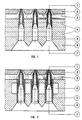
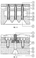
- the present die for hot die face cutting thermoplastic polymers comprises a body (6), a bored metal plate (2) and a layer (3) of insulating material positioned between the body (6) and the plate (2).
- the body (6) is provided with channels (5) for the polymer flow drilled in the body itself or applied to the same, each of them with a conical mouth (7).
- Each channel (5) is provided with a nozzle (1) made of material having a thermal conductivity higher than 60 W/m°K, rooted inside the die body (6) and coming out of the same in a way as to cross the insulating layer (3) and plate (2).
- Said nozzle (1) at its bottom end, is in thermal contact with the thermostated die body (6) and, in its protruding part, is completely coated with the insulating material (3).
- the nozzle (1) is fixed to the channel (5) by a fixed fitting up with step-stop (see figures 1 and 2) or by a removable fitting up (see figure 4).
- the die body (6) is preferably constituted by two separate sections and the nozzles (1) are blocked between said two sections fastened with screws.
- Figure 3 illustrates a particular embodiment of the present die, wherein each nozzle (1') constitutes a single block with each channel (5').
- the insulating layer (3) extends as far as to cover the end part of each nozzle (1) in order to prevent heat losses.
- thermoregulating system can comprise a plurality of channels (4), as shown in figures 1 and 4, or a chamber (4'), as shown in figures 2 and 3, in which the thermostated fluid is circulated.
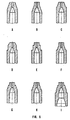
- the external profiles of the nozzle ends shown in figure 5 represent possible configurations which can be selected according to the process conditions in order to comply with different needs such as: to limit heat losses in the nozzles; to favour the heat flow towards the end part of the nozzles; to provide a supporting and coupling surface for the insulating material, thus making it capable of avoiding the penetration or infiltration of the process refrigerating fluid, specially when said fluid is under pressure.
- embodiments 5A-5D have a lower dispersing surface, while other embodiments, such as for example 5E-51, are endowed with better sealing.
Landscapes
- Engineering & Computer Science (AREA)
- Mechanical Engineering (AREA)
- Manufacturing & Machinery (AREA)
- Physics & Mathematics (AREA)
- Thermal Sciences (AREA)
- Processing And Handling Of Plastics And Other Materials For Molding In General (AREA)
- Extrusion Moulding Of Plastics Or The Like (AREA)
- Perforating, Stamping-Out Or Severing By Means Other Than Cutting (AREA)
- Moulds For Moulding Plastics Or The Like (AREA)
- Details Of Cutting Devices (AREA)
- Turning (AREA)
Claims (12)
dadurch gekennzeichnet, daß die Düse zusätzlich ein Wärmeregulierungssystem (4) für den Düsenkörper (6) umfaßt, das mindestens den Endteil der Kanäle (5) umgibt, die Düsenmundstücke (1) aus einem Metallmaterial hergestellt sind, das eine Wärmeleitfähigkeit über 60 W/m°K hat und das isolierende Material (3) dem äußeren Profil des Düsenmundstückes (1) und dem inneren Profil der Platte (2) anpaßt und das Düsenmundstück bis zu seinem freien Ende isoliert.
Priority Applications (1)
| Application Number | Priority Date | Filing Date | Title |
|---|---|---|---|
| AT85101080T ATE42926T1 (de) | 1984-02-02 | 1985-02-01 | Duese zum heissabschlaggranulieren von thermoplastischen polymeren. |
Applications Claiming Priority (2)
| Application Number | Priority Date | Filing Date | Title |
|---|---|---|---|
| IT19387/84A IT1174480B (it) | 1984-02-02 | 1984-02-02 | Filiera per il taglio a caldo di polimeri termoplastici |
| IT1938784 | 1984-02-02 |
Publications (2)
| Publication Number | Publication Date |
|---|---|
| EP0152844A1 EP0152844A1 (de) | 1985-08-28 |
| EP0152844B1 true EP0152844B1 (de) | 1989-05-10 |
Family
ID=11157253
Family Applications (1)
| Application Number | Title | Priority Date | Filing Date |
|---|---|---|---|
| EP85101080A Expired EP0152844B1 (de) | 1984-02-02 | 1985-02-01 | Düse zum Heissabschlaggranulieren von thermoplastischen Polymeren |
Country Status (8)
| Country | Link |
|---|---|
| US (1) | US4678423A (de) |
| EP (1) | EP0152844B1 (de) |
| JP (1) | JPS60236709A (de) |
| AT (1) | ATE42926T1 (de) |
| CA (1) | CA1245820A (de) |
| DE (1) | DE3570061D1 (de) |
| ES (1) | ES295028Y (de) |
| IT (1) | IT1174480B (de) |
Families Citing this family (37)
| Publication number | Priority date | Publication date | Assignee | Title |
|---|---|---|---|---|
| JPS6250107A (ja) * | 1985-06-21 | 1987-03-04 | Toyo Seikan Kaisha Ltd | 樹脂供給装置 |
| US4752196A (en) * | 1986-05-22 | 1988-06-21 | Rogers Tool Works, Inc. | Internally insulated extrusion die |
| DE3809735C1 (de) * | 1988-03-23 | 1989-06-08 | Werner & Pfleiderer Gmbh, 7000 Stuttgart, De | |
| US5403176A (en) * | 1991-02-01 | 1995-04-04 | Gala Industries, Inc. | Tapered insert die plate for underwater pelletizers |
| JPH06166025A (ja) * | 1992-11-30 | 1994-06-14 | Nippon Purakon Kk | ストランドダイス |
| US5643618A (en) * | 1994-05-11 | 1997-07-01 | General Mills, Inc. | Apparatus for making multiple, complexly patterned extrudates |
| DE19515473A1 (de) * | 1995-04-27 | 1996-10-31 | Werner & Pfleiderer | Unterwasser-Granulierlochplatte mit Verschleißschutzschicht |
| DE19638994B4 (de) * | 1996-09-23 | 2009-02-26 | Bühler AG | Vorrichtung zum Homogenisieren, Mischen und/oder Granulieren von chemischen Stoffen |
| US5843503A (en) * | 1997-02-24 | 1998-12-01 | General Mills, Inc. | Apparatus and method for making multiple patterned extrudates |
| RU2146195C1 (ru) * | 1997-11-03 | 2000-03-10 | Институт физики прочности и материаловедения СО РАН | Фильера гранулятора полимерных материалов |
| US6251452B1 (en) | 1999-04-23 | 2001-06-26 | General Mills, Inc. | Apparatus and methods for making multiple, complexly patterned extrudates |
| US20030131791A1 (en) * | 2000-11-21 | 2003-07-17 | Schultz Carl L. | Multiple orifice applicator system and method of using same |
| US6976834B2 (en) * | 2001-07-09 | 2005-12-20 | Borsig Gmbh | Pelletizing die with even heat distribution and with polymer channel to orifice transition zone, process for orifice thermal stabilization and process for forming a pelletizing die with brazing and thin hard face layer |
| ITMI20012706A1 (it) * | 2001-12-20 | 2003-06-20 | Enichem Spa | Procedimento per la produzione di granuli di polimeri termoplastici espandibili ed apparecchiatura adatta allo scopo |
| ITMI20012708A1 (it) * | 2001-12-20 | 2003-06-20 | Enichem Spa | Dispositivo per la granulazione a caldo di polimeri termolastici |
| US20040115298A1 (en) * | 2002-10-22 | 2004-06-17 | Gerhard Hehenberger | Arrangement including a granulating head, apertured granulating plate |
| US7226553B2 (en) * | 2003-07-30 | 2007-06-05 | E. I. Du Pont De Nemours And Company | Polymer underwater pelletizer apparatus and process incorporating same |
| US7658874B2 (en) * | 2003-07-30 | 2010-02-09 | E.I. Du Pont De Nemours And Company | Polymer pelletization process and apparatus |
| US7632086B2 (en) * | 2003-10-03 | 2009-12-15 | Exxonmobil Chemical Patents Inc. | Melt fracture reduction |
| US7316557B2 (en) * | 2004-05-08 | 2008-01-08 | Good Earth Tools, Inc. | Die for extruding material |
| AT505845B1 (de) * | 2004-04-28 | 2009-05-15 | Hehenberger Gerhard | Anordnung mit einem granulierkopf eines extruders |
| RU2313454C1 (ru) * | 2006-06-02 | 2007-12-27 | Государственное образовательное учреждение высшего профессионального образования "Уфимский государственный нефтяной технический университет" | Фильера гранулятора пластмасс |
| CN101165086B (zh) | 2006-10-17 | 2011-07-20 | 江苏圣奥化学科技有限公司 | 球形橡胶助剂及其制备方法 |
| WO2008102874A1 (ja) * | 2007-02-23 | 2008-08-28 | Sekisui Plastics Co., Ltd. | 造粒用ダイス、造粒装置及び発泡性熱可塑性樹脂粒子の製造方法 |
| DE202007003495U1 (de) * | 2007-03-08 | 2007-07-05 | Rieter Automatik Gmbh | Vorrichtung zur Erzeugung von Granulatkörnern aus einer Kunststoffschmelze |
| JP4996547B2 (ja) * | 2008-06-05 | 2012-08-08 | 株式会社日本製鋼所 | 樹脂ペレット製造用ダイス及びその温度調整方法 |
| DE202009014544U1 (de) | 2009-10-28 | 2010-03-18 | Automatik Plastics Machinery Gmbh | Lochplatte einer Granuliervorrichtung |
| AT508894B1 (de) * | 2010-06-22 | 2011-05-15 | Hehenberger Gerhard | Vorrichtung zum granulieren von kunststoff |
| DE102011008257A1 (de) | 2011-01-11 | 2012-07-12 | Automatik Plastics Machinery Gmbh | Lochplatte |
| US20130078328A1 (en) * | 2011-09-27 | 2013-03-28 | Kennametal, Inc. | Coated Pelletizing Dies |
| US9314985B2 (en) | 2011-09-27 | 2016-04-19 | Kennametal Inc. | Coated pelletizing extrusion dies and method for making the same |
| EP2617546A1 (de) | 2012-01-20 | 2013-07-24 | Automatik Plastics Machinery GmbH | Verfahren zum Beheizen von Schmelzekanälen in einer Lochplatte und Verfahren zum Granulieren einer Polymerschmelze |
| PL2617547T3 (pl) | 2012-01-20 | 2017-08-31 | Maag Automatik Gmbh | Płyta perforowana, wkładka płyty perforowanej i ich zastosowanie |
| GB2517191A (en) * | 2013-08-14 | 2015-02-18 | Univ Graz Tech | Hot viscous raw material leaving a cooler perforated body cooling a cutter |
| AT520317B1 (de) * | 2018-02-01 | 2019-03-15 | Econ Gmbh | Granulierkopf-Platte und Verfahren zur Herstellung einer Granulierkopf-Platte |
| US11097474B2 (en) * | 2018-09-10 | 2021-08-24 | Stratasys, Inc. | Extrusion tip insert for use in additive manufacturing system |
| AT524541B1 (de) | 2021-04-07 | 2022-07-15 | Engel Austria Gmbh | Vorrichtung zum Entgasen und Verfahren zum Entgasen einer plastifizierten Masse |
Family Cites Families (13)
| Publication number | Priority date | Publication date | Assignee | Title |
|---|---|---|---|---|
| US3436449A (en) * | 1966-02-03 | 1969-04-01 | Ici Ltd | Granulation of theromplastic materials |
| DE1604344B2 (de) * | 1966-12-14 | 1972-12-14 | Barmag Barmer Maschinenfabrik Ag, 5600 Wuppertal | Spritzwerkzeug in unterwassergranulatoren |
| US3599285A (en) * | 1968-10-10 | 1971-08-17 | Myron & Mallay | Pelletizing die plate |
| US3599286A (en) * | 1968-11-12 | 1971-08-17 | Norton Co | Thermally insulated extrusion die and method of making |
| US3618162A (en) * | 1969-10-02 | 1971-11-09 | Usm Corp | Plastic pelletizer underwater pelletizing head |
| GB1350012A (en) * | 1970-12-28 | 1974-04-18 | Barmag Barmer Maschf | Extrusion die for granulators |
| DE2543450A1 (de) * | 1975-09-29 | 1976-04-15 | Shell Int Research | Vorrichtung zum granulieren von thermoplastischen kunststoffen |
| US4123207A (en) * | 1976-03-29 | 1978-10-31 | Gala Industries, Inc. | Underwater pelletizer and heat exchanger die plate |
| JPS6053864B2 (ja) * | 1978-12-06 | 1985-11-27 | 富士写真フイルム株式会社 | ゼラチン分散溶液のヌ−ドル化装置 |
| US4378964A (en) * | 1980-01-08 | 1983-04-05 | Trw Inc. | Internally insulated extrusion die |
| US4327050A (en) * | 1980-09-22 | 1982-04-27 | Phillips Petroleum Company | Extrusion and pelleting apparatus and method |
| US4564350A (en) * | 1982-06-10 | 1986-01-14 | Thomas R. Vigil | Plastic extruder assembly |
| DE3243332A1 (de) * | 1982-07-15 | 1984-01-26 | Gala Industries, Inc., 24085 Virginia | Spritzgussduese |
-
1984
- 1984-02-02 IT IT19387/84A patent/IT1174480B/it active
-
1985
- 1985-01-29 CA CA000473083A patent/CA1245820A/en not_active Expired
- 1985-01-31 US US06/696,740 patent/US4678423A/en not_active Expired - Fee Related
- 1985-02-01 EP EP85101080A patent/EP0152844B1/de not_active Expired
- 1985-02-01 AT AT85101080T patent/ATE42926T1/de not_active IP Right Cessation
- 1985-02-01 DE DE8585101080T patent/DE3570061D1/de not_active Expired
- 1985-02-01 JP JP60016709A patent/JPS60236709A/ja active Granted
- 1985-02-01 ES ES1985295028U patent/ES295028Y/es not_active Expired
Also Published As
| Publication number | Publication date |
|---|---|
| ES295028Y (es) | 1988-05-01 |
| JPH0583363B2 (de) | 1993-11-25 |
| ATE42926T1 (de) | 1989-05-15 |
| CA1245820A (en) | 1988-12-06 |
| JPS60236709A (ja) | 1985-11-25 |
| IT8419387A0 (it) | 1984-02-02 |
| ES295028U (es) | 1987-10-16 |
| DE3570061D1 (en) | 1989-06-15 |
| US4678423A (en) | 1987-07-07 |
| IT1174480B (it) | 1987-07-01 |
| EP0152844A1 (de) | 1985-08-28 |
Similar Documents
| Publication | Publication Date | Title |
|---|---|---|
| EP0152844B1 (de) | Düse zum Heissabschlaggranulieren von thermoplastischen Polymeren | |
| US4123207A (en) | Underwater pelletizer and heat exchanger die plate | |
| US4564350A (en) | Plastic extruder assembly | |
| EP2018257B1 (de) | Matrizenplatte mit fester fläche | |
| JPS6322612A (ja) | 内側が断熱された押出しダイ | |
| CA2469828C (en) | Device for the hot granulation of thermoplastic polymers | |
| US4264553A (en) | Method of underwater granulation | |
| TWI471211B (zh) | 用於空心顆粒之擠壓成形的方法與裝置 | |
| US6474969B1 (en) | Extrusion die and die assembly for underwater pelletizer | |
| US4710113A (en) | Apparatus for granulating plastics materials | |
| KR102005647B1 (ko) | 개구된 하류측 면이 중실 면 플레이트에 의해 덮인 플레이트 바디를 갖는 다이 플레이트 | |
| US20160185012A1 (en) | Hot viscous raw material leaving a cooler perforated body cooling a cutter | |
| MX2011001676A (es) | Ensamble de placa de dado termicamente aislado para peletizacion submarina y similares. | |
| US5679380A (en) | Underwater pelletizing die plate | |
| US6976834B2 (en) | Pelletizing die with even heat distribution and with polymer channel to orifice transition zone, process for orifice thermal stabilization and process for forming a pelletizing die with brazing and thin hard face layer | |
| US6638045B2 (en) | Die for manufacturing resin pellets | |
| US4958933A (en) | Cooler-extruder device | |
| US7367792B2 (en) | Arrangement with an extrusion die of an extruder | |
| EP0293269B1 (de) | Extruderdüse | |
| US4120625A (en) | Die face cutter | |
| JP2014505608A (ja) | 穴あきプレート | |
| CN110202771A (zh) | 一种造粒模板用真空隔热盖板 | |
| CA1081423A (en) | Extruding followed by cooling and lubricating of the extrudate | |
| US20040253336A1 (en) | Extruder with heating elements | |
| JPS62279905A (ja) | 造粒装置 |
Legal Events
| Date | Code | Title | Description |
|---|---|---|---|
| PUAI | Public reference made under article 153(3) epc to a published international application that has entered the european phase |
Free format text: ORIGINAL CODE: 0009012 |
|
| AK | Designated contracting states |
Designated state(s): AT BE CH DE FR GB LI NL |
|
| 17P | Request for examination filed |
Effective date: 19860123 |
|
| 17Q | First examination report despatched |
Effective date: 19860926 |
|
| GRAA | (expected) grant |
Free format text: ORIGINAL CODE: 0009210 |
|
| AK | Designated contracting states |
Kind code of ref document: B1 Designated state(s): AT BE CH DE FR GB LI NL |
|
| REF | Corresponds to: |
Ref document number: 42926 Country of ref document: AT Date of ref document: 19890515 Kind code of ref document: T |
|
| REF | Corresponds to: |
Ref document number: 3570061 Country of ref document: DE Date of ref document: 19890615 |
|
| ET | Fr: translation filed | ||
| PLBE | No opposition filed within time limit |
Free format text: ORIGINAL CODE: 0009261 |
|
| STAA | Information on the status of an ep patent application or granted ep patent |
Free format text: STATUS: NO OPPOSITION FILED WITHIN TIME LIMIT |
|
| 26N | No opposition filed | ||
| PGFP | Annual fee paid to national office [announced via postgrant information from national office to epo] |
Ref country code: GB Payment date: 19940124 Year of fee payment: 10 |
|
| PGFP | Annual fee paid to national office [announced via postgrant information from national office to epo] |
Ref country code: DE Payment date: 19940209 Year of fee payment: 10 |
|
| PGFP | Annual fee paid to national office [announced via postgrant information from national office to epo] |
Ref country code: FR Payment date: 19940210 Year of fee payment: 10 |
|
| PGFP | Annual fee paid to national office [announced via postgrant information from national office to epo] |
Ref country code: AT Payment date: 19940214 Year of fee payment: 10 |
|
| PGFP | Annual fee paid to national office [announced via postgrant information from national office to epo] |
Ref country code: CH Payment date: 19940215 Year of fee payment: 10 |
|
| PGFP | Annual fee paid to national office [announced via postgrant information from national office to epo] |
Ref country code: NL Payment date: 19940228 Year of fee payment: 10 |
|
| PGFP | Annual fee paid to national office [announced via postgrant information from national office to epo] |
Ref country code: BE Payment date: 19940408 Year of fee payment: 10 |
|
| PG25 | Lapsed in a contracting state [announced via postgrant information from national office to epo] |
Ref country code: GB Effective date: 19950201 Ref country code: AT Effective date: 19950201 |
|
| PG25 | Lapsed in a contracting state [announced via postgrant information from national office to epo] |
Ref country code: LI Effective date: 19950228 Ref country code: CH Effective date: 19950228 Ref country code: BE Effective date: 19950228 |
|
| BERE | Be: lapsed |
Owner name: MONTEDISON S.P.A. Effective date: 19950228 |
|
| PG25 | Lapsed in a contracting state [announced via postgrant information from national office to epo] |
Ref country code: NL Effective date: 19950901 |
|
| GBPC | Gb: european patent ceased through non-payment of renewal fee |
Effective date: 19950201 |
|
| PG25 | Lapsed in a contracting state [announced via postgrant information from national office to epo] |
Ref country code: FR Effective date: 19951031 |
|
| NLV4 | Nl: lapsed or anulled due to non-payment of the annual fee |
Effective date: 19950901 |
|
| PG25 | Lapsed in a contracting state [announced via postgrant information from national office to epo] |
Ref country code: DE Effective date: 19951101 |
|
| REG | Reference to a national code |
Ref country code: FR Ref legal event code: ST |