EP0151815B1 - Schwingungserzeuger mit hohem Durchflussvermögen - Google Patents
Schwingungserzeuger mit hohem Durchflussvermögen Download PDFInfo
- Publication number
- EP0151815B1 EP0151815B1 EP84116507A EP84116507A EP0151815B1 EP 0151815 B1 EP0151815 B1 EP 0151815B1 EP 84116507 A EP84116507 A EP 84116507A EP 84116507 A EP84116507 A EP 84116507A EP 0151815 B1 EP0151815 B1 EP 0151815B1
- Authority
- EP
- European Patent Office
- Prior art keywords
- interaction chamber
- sidewalls
- nozzle
- flow
- inlet
- Prior art date
- Legal status (The legal status is an assumption and is not a legal conclusion. Google has not performed a legal analysis and makes no representation as to the accuracy of the status listed.)
- Expired
Links
Images

Classifications
-
- A—HUMAN NECESSITIES
- A46—BRUSHWARE
- A46B—BRUSHES
- A46B11/00—Brushes with reservoir or other means for applying substances, e.g. paints, pastes, water
-
- A—HUMAN NECESSITIES
- A46—BRUSHWARE
- A46B—BRUSHES
- A46B15/00—Other brushes; Brushes with additional arrangements
- A46B15/0002—Arrangements for enhancing monitoring or controlling the brushing process
-
- A—HUMAN NECESSITIES
- A46—BRUSHWARE
- A46B—BRUSHES
- A46B15/00—Other brushes; Brushes with additional arrangements
- A46B15/0002—Arrangements for enhancing monitoring or controlling the brushing process
- A46B15/0016—Arrangements for enhancing monitoring or controlling the brushing process with enhancing means
-
- B—PERFORMING OPERATIONS; TRANSPORTING
- B05—SPRAYING OR ATOMISING IN GENERAL; APPLYING FLUENT MATERIALS TO SURFACES, IN GENERAL
- B05B—SPRAYING APPARATUS; ATOMISING APPARATUS; NOZZLES
- B05B1/00—Nozzles, spray heads or other outlets, with or without auxiliary devices such as valves, heating means
- B05B1/02—Nozzles, spray heads or other outlets, with or without auxiliary devices such as valves, heating means designed to produce a jet, spray, or other discharge of particular shape or nature, e.g. in single drops, or having an outlet of particular shape
- B05B1/08—Nozzles, spray heads or other outlets, with or without auxiliary devices such as valves, heating means designed to produce a jet, spray, or other discharge of particular shape or nature, e.g. in single drops, or having an outlet of particular shape of pulsating nature, e.g. delivering liquid in successive separate quantities
-
- F—MECHANICAL ENGINEERING; LIGHTING; HEATING; WEAPONS; BLASTING
- F15—FLUID-PRESSURE ACTUATORS; HYDRAULICS OR PNEUMATICS IN GENERAL
- F15C—FLUID-CIRCUIT ELEMENTS PREDOMINANTLY USED FOR COMPUTING OR CONTROL PURPOSES
- F15C1/00—Circuit elements having no moving parts
- F15C1/22—Oscillators
-
- A—HUMAN NECESSITIES
- A46—BRUSHWARE
- A46B—BRUSHES
- A46B2200/00—Brushes characterized by their functions, uses or applications
- A46B2200/10—For human or animal care
- A46B2200/1066—Toothbrush for cleaning the teeth or dentures
-
- Y—GENERAL TAGGING OF NEW TECHNOLOGICAL DEVELOPMENTS; GENERAL TAGGING OF CROSS-SECTIONAL TECHNOLOGIES SPANNING OVER SEVERAL SECTIONS OF THE IPC; TECHNICAL SUBJECTS COVERED BY FORMER USPC CROSS-REFERENCE ART COLLECTIONS [XRACs] AND DIGESTS
- Y10—TECHNICAL SUBJECTS COVERED BY FORMER USPC
- Y10T—TECHNICAL SUBJECTS COVERED BY FORMER US CLASSIFICATION
- Y10T137/00—Fluid handling
- Y10T137/206—Flow affected by fluid contact, energy field or coanda effect [e.g., pure fluid device or system]
- Y10T137/2273—Device including linearly-aligned power stream emitter and power stream collector
Definitions
- the present invention relates to a fluidic oscillator as mentioned in the introductory parts of the independent claims 1 and 4.
- Fluid oscillators and nozzles demand structural and operating constraints. Such constraints include extremely small size, relatively high flow rates, low head loss, low oscillation frequencies, and waveforms that produce relatively even flow distributions over the output sweep area-all to achieve high efficiency and efficacy in use and application of the moving fluid.
- Such uses include cooling, heating, wetting, drying, washing, cleaning, rinsing, and scaling; application of chemicals, paints, adhesives, insecticides, and the like; the stimulation of body surfaces, tissues, and of blood circulation; the debridement of wounds; the dispersal of liquids into gases and vice versa; and, the mixing of gases and liquids.
- a fluid oscillator as mentioned above having hitherto unattainable combinations of advantageous properties, such as extremely small size and relatively low frequencies, together with high flow rates and low head loss; and having a size that is small enough to be suitable for use within a toothbrush; and, effective to wet bristles and to dispense water or appropriate chemical solutions over the brushed regions of teeth and gums, to help cleanse teeth and oral tissues, to flush out particles, and to stimulate blood circulation in oral tissues.
- the fluid oscillator of the present invention utilizes a supply nozzle to accelerate a jet of fluid into a short and relatively narrow, elongated and specially-shaped interaction chamber.
- the jet is caused to oscillate within the chamber transversely to the flowing jet in the plane of the chamber by the inertance action of a column of fluid which alternately interacts with the transverse deflectional compliance of the jet.
- the column of fluid is alternately contained between the two sides of the chamber alongside of the jet and a conduit or channel interconnecting the two chamber sides along the jet.
- An inlet conduit leading to the supply nozzle is shaped to provide uniform fluid velocity distribution and to avoid undesirable flow separations upstream from the nozzle exit even at relatively high flow velocities or oscillator configurations such as where supply fluid enters the oscillator at a right angle to the plane of the chamber.
- the fluid oscillator of the present invention has no moving parts and sustains oscillation by using a portion of the fluid energy supplied to a fluid-dynamic gain mechanism comprising a fluid, parallel, compliance/inertance circuit.
- the flow through the oscillator is in the form of a jet or stream that is alternately deflected from side to side within the device before exiting with an oscillatory motion that sweeps from side to side over a given angle.
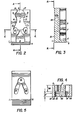
- the oscillator of Figs. 2-5 comprises a plate-shaped body 1 having fluid flow channels or passages formed therein.
- Cover plate 2 covers flow passages on the rear side 21 of body 1 and cover plate 3 covers flow passages on the front side 5 of body 1.
- Cover 3 also provides a fluid supply passage 4 which is normal to the plate 3 and the plane of the main passages on front side 5 of body 1.
- the main fluid flow passages are formed to some depth in the front side 5 of body 1 and comprise an inlet plenum chamber 6, at least partially located in direct flow communication with supply passage 4. Chamber 6 narrows down toward a supply or power nozzle 7 which is directed into an elongated interaction chamber 9 and pointed toward an output opening 8 at the other end of body 1.
- the power nozzle enters directly into the chamber 9 without first passing between control nozzles or the like as in most conventional oscillators such as those described in U.S. Patent 4,052,002 or Japanese patent publication 54-181013.
- the oscillator of the invention is characterized by the absence of such control nozzles.
- Chamber 9 is generally. of an hour-glass shape.
- chamber walls 10 and 11 on either side of nozzle 7 first converge gradually in a downstream direction toward a narrower chamber neck 12 between convex wall portions 13 and 14 located at a distance somewhat more than halfway between nozzle 7 and output opening 8. Thereafter the sidewalls diverge downstream to a concavity having a maximum width across points 15 and 16 before again converging toward output opening 8, defined between wall edges 17 and 18.
- the depth of the plenum chamber 6, nozzle 7, and interaction chamber 9 may be constant or gradually increasing or decreasing in any direction. In fact, the depth may vary in other manners as long as the described and illustrated two-dimensional silhouette outline is substantially preserved.
- connecting-openings 19 and 20-one are elongated, oval holes at right angles to the plane of body 1 and reach through it to a passage 22 in the rear side 21 of body 1-the passage 22 thereby being “folded", so-to-speak.
- the fluid passage 22 interconnects the connecting openings 19 and 10 and has a somewhat horseshoe-shaped outline, with the two ends of the horseshoe shape leading into connecting openings 19 and 20.
- the shape and depth of fluid passage 22 are such that its cross-sectional flow area and length do not cause unreasonable flow head losses during operation.
- the horseshoe-like shape for passage 22 has production advantages when the body is injection molded.
- passage 22 and connecting openings 19 and 20 may be variously shaped and located without particular adverse influences on oscillator function and performance.
- passage 22 may be lengthened or shortened and its cross-sectional area may be changed or varied either by width or by depth or both in accordance with particular performance requirements, design goals, or manufacturing methods.
- Passage 22, for instance, may be in form of one or more drilled or molded holes in body 1 that crossconnect openings 19 and 20 and are later capped-off.
- Passage 22, for example can be molded as blind holes from front side 5 to a depth below the passages in side 5 so that the cover plate 1 can be eliminated.
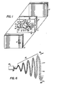
- Fig. 6 schematically shows an image of an instantaneous output flow pattern from an oscillator of the present invention when used as a spray nozzle.
- a stream of fluid 24 issues from the output of an oscillator 23 with a smoothly-changing, back-and-forth flow direction between indicated extreme angular deflection amplitudes 25 and 26.
- the thusly oscillating output flow may break up (if it is a liquid issuing into a gas ambient state, for instance) or it may remain a more cohesive, but gradually dissipating flow stream (if, for instance, it is a liquid or gas issuing into an ambient state of the same phase).
- the resulting instantaneous output flow pattern follows the wave pattern 27 depicted in Fig. 6 which has a desirable sine-wave-like or triangular-wave-like appearance, moving away from nozzle 23 at the general output velocity of the flow which is gradually diminished by ambient damping influences.
- Flows impacting on surfaces in an interrupted manner provide, among other benefits, enhanced surface wetting, cleaning, drying, cooling, and heating effects.
- the impact and momentum influences of interrupted flows on materials or tissues can cause in-depth effects which are not obtainable from steady and continuous flows. Such effects are advantageous and desirable, for example, in increasing blood circulation and tissue stimulation such as when applied to gingiva or other tissues.
- Fig. 7 illustrates a momentary flow state within the silhouette of the oscillator's interaction chamber when fluid is initially fed to the device.
- supply fluid enters plenum 6 (not shown in Fig. 7); is accelerated through nozzle 7 into interaction chamber 9 as a jet flow 28; and, leaves through output opening 8.
- Figs. 8-12 illustrate sequential momentary flow states in the course of a half-period of oscillation.
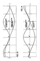
- the jet 28 As the jet 28 is deflected back and forth, it stores potential energy as shown in Fig. 13 where deflection and potential energy are plotted versus time.
- Fig. 14 plots the time relation of the velocity of this fluid column and the kinetic energy contained in the motion of the fluid column. Both graphs span a portion of somewhat more than one half oscillation period and correspond to the flow state representations of Figs. 8 through 12. Approximate timing correlations between the graphs and Figs. 8-12 are indicated by vertical solid and dashed lines, marked by primed numerals 8'-12'.
- the fluid column is a fluid inertance and the transversely-deflectable jet flow 28 is a fluid compliance.
- the transversely-deflectable jet flow 28 is a fluid compliance.
- the solid graph line represents the transverse jet flow deflection and the dashed graph-line represents the jet's corresponding potential energy level.
- the solid graph-line represents the fluid column velocity and the dashed graph-line represents the corresponding kinetic energy level.
- the potential energy stored by the jet's deflection and the meaning of the deflection itself is similar to the following mechanical analogy.
- the jet flow 28 through chamber 9 is an elastic diaphragm which separates the chamber into two halves. If there is more fluid in one half than in the other, the diaphragm is deflected or strained toward the side with the lesser fluid content. This elastically strained diaphragm then stores potential energy.
- the indicated deflection of jet flow 28 corresponds to the stored potential energy, but it is not necessarily a precise representation of the actual potential energy which would also be a function of certain other chamber effects. Rather, it is a measure of an idealized jet deflection and potential energy if a linear stress/strain relationship existed.
- Figs. 7-12 are marked by arrows and + or - signs to represent the sign and direction of deflection of jet flow 28 and the sign of the direction of the fluid column velocity.
- jet flow 28 traverses interaction chamber 9 and exits through output opening 8.
- Always existing instabilities and asymmetries of flow or structure cause a jet flow deflection; and, pressure differences across the sides of the jet increase this deflection.
- If passages have not been previously filled with fluid some of the jet flow 28 peels off in a reverse flow, particularly from the higher pressure chamber side, and the passages are filled. Once the passages are filled, the peeled back flow may not enter or move through connection openings 19 or 20 due to the inertance of the fluid column including that contained in the interconnecting passage 22. This condition, as schematically indicated by arrows in Fig.
- Fig. 8 may persist for a short time, wherein peeled-off flow on the higher-pressure side of the jet pressurizes this side further, but recirculates and is again entrained by the jet flow 28. Similarly the other, lower pressure side of the jet recirculates a minimal flow in the narrowing space between the jet and the adjacent chamber wall; and, the state shown in Fig. 8 is approached. Although difference starting circumstances result in different initial conditions, a state such as illustrated in Fig. 8 (or its mirror image) is approached within a very short time.
- Fig. 9 the pressure differential across the sides of jet flow 28 is somewhat relieved by crossflow into opening 19, and through passage 22 and out of opening 20. This crossflow is indicated by double flow line arrows and its direction is indicated by a (-) sign in opening 19. At this time, jet flow 28 has somewhat straightened.out due to the reduced pressure differential across its sides. It is very significant that the fluid column is still being accelerated in the same (-) direction as before due to the still-remaining pressure differential across sides of the jet.
- jet flow 28 is somewhat deflected in the negative direction toward wall 11 and flow through the fluid column is being decelerated, but the flow remains in the previous (negative) direction.
- the fluid column is still at high velocity, as indicated by double flow-line arrows.
- increasing peel-off and the still inflowing flow of the fluid column begin to more strongly pressurize the upper side of the chamber.
- jet flow 28 attains its extreme deflection amplitude in the negative direction toward wall 11 as shown in Fig. 12. At this time the oscillating energy is stored as potential energy in the jet flow 28. It is axiomatic that this energy is the same as the maximum kinetic energy of the fluid column when it is moving at its maximum velocity as shown for instance in Fig. 10.
- Fig. 12 represents a flow state which is the mirror image of the state shown in Fig. 8.
- Fig. 8 applies to Fig. 12 in a side-reversed manner.
- the pressure difference across jet flow 28 tends to sustain the jet's deflection until the fluid column begins to accelerate- subsequent to the state of Fig. 12-in the then positive direction.
- Figs. 8 to 12 are representative of a half-period of the jet's oscillation.
- the second half-period follows in a side-reversed and sign-reversed manner with further oscillation periods cyclically repeating what has just been described.
- Fig. 6 shows the resulting output flow directions and the ensuing wave pattern 27 through several oscillation cycles further downstream from output opening 8.
- Figs. 15 and 16 set forth the more important relative silhouette dimensions of a preferred embodiment of the oscillator of the invention.
- the corresponding depth dimensions of the same embodiment are illustrated in Fig. 4.
- the identifying letters in those Figures are further defined in the following Table I.
- all of the dimensions in Table I are expressed as ratios of actual dimensions divided by the reference width W of nozzle 7 (Figs. 1, 2, 4, 5, through 12).
- W of nozzle 7 Figs. 1, 2, 4, 5, through 12
- Table I An actual dimension of nozzle width W is also given in Table I for a specific preferred embodiment.
- the given ranges of relative dimensions indicate tolerance ranges within which gross performance changes are not exhibited.
- a preferred embodiment of the present invention has relative dimensions as indicated in Table I. Actual dimensions, for example for a miniature oscillator, can be obtained by reference to the supply nozzle width W.
- FIG. 12 A couple of the more important relative dimensions are graphed in Fig. 12 showing a range of relationships between the relative dimensions O and L (see Fig. 15).
- Useful performance properties are obtained in the partly-hatched region below the thick graph line A, when used with water-like fluids issuing into air-the dotted region between the graph lines A and B indicates a functional regime for gas-in-gas or submerged operation.
- the blank region above line B represents dimensions which are unlikely to provide useful functions. It should be kept in mind, however, that even the important relationships given in Fig. 18 are by example only and are subject to substantive change due to the strong and varied interdependence of many of the dimensional parameters, as pointed out before. Consequently, the graphed relationships are to be viewed as typical examples, rather than as an invariable rule.
- the black oval region C represents the parameters utilized in a preferred embodiment described in connection with Figs. 1 through 16.
- Spray fan angle changes may be accomplished by changes in the relative output opening 8 (dimension “0" in the tables) and additionally by suitable shape changes of chamber 9, particularly in the downstream portion. Relatively minor angle changes, however, will also occur due to other dimensional variations.
- the oscillator's operating frequency is influenced by the shape and size of passage 22 and holes 19 and 20 and their flow communication paths along the sides of chamber 9 to and from wall edges 17 and 18, as shown in Figs. 1 through 5.
- the fluid column extending as it does along both sides of the jet 28 for almost the entire length of the reaction chamber 9, represents the inertance of a resonant, parallel, fluid compliance-inertance circuit of the oscillator.
- the fluid column influences the frequency of oscillation substantially as the inverse square root of its inertance property.
- this inertance is directly proportional to column length and fluid density and inversely proportional to the cross sectional area of the column as has been well known since Lord Rayleigh's days.
- frequency can be changed by making appropriate changes to the dimensions of the passages of the fluid column inertance.
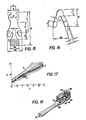
- FIG. 18 illustrates a toothbrush head together with a part of its stem and handle.
- the toothbrush comprises a head and stem body 29 from whose top surface 35 a number of bristles 30 protrude in a conventional manner.
- the head and stem body 29 contains a fluid supply conduit 31 which is fed by a suitable fluid flow supply source (not shown).
- Conduit 31 reaches into a cavity 36 extending from the top surface 35 to at least below the entry of conduit 31.
- An oscillator nozzle 32 of the type depicted in Figs. 1 through 5, is contained as a sealed assembly within cavity 36 such that supply conduit 31 leads into fluid supply passage 34 of oscillator nozzle 32 wherein passage 34 corresponds to passage 4 of Fig. 1.
- Oscillator nozzle 32 is oriented with its oscillation plane at a right angle to supply flow conduit 31 and with its output opening 33 (corresponding to opening 8 of Fig. 1) facing substantially in the same upward direction as bristles 30.
- oscillator nozzle 32 is supplied with fluid flow through conduit 31 so that fluid issues in an oscillating flow stream making a fan-shaped spray pattern. Initially the spray is at least partially surrounded by the bundles of bristles 30. During toothbrushing, the resulting oscillating flow and spray pattern aid in the action of toothcleaning by releasing, rinsing, and flushing out particles from between teeth and from the gum line. This action, therefore, aids in the removal of decay-forming matter and bacteria, stimulates blood circulation in oral tissues, and massages the gums. Although some of these effects may be achieved to some lesser extent by steady or interrupted unidirectional flows, others are attainable to any significant degree only by means of oscillating flows generated by nozzles of the present invention. All of these actions have been shown to be significantly effective, particularly in conjunction with the normal tooth brushing action, but these effects may be appropriately enhanced by suitable chemicals added to the liquid.
- the general size of a toothbrush requires an oscillator nozzle of a very small size because nozzle 32 must be no longer than the depth or thickness of body 29 below bristles 30 (or only minimally longer, if some small protrusion into the bristle region is acceptable).
- the oscillator nozzle must also be narrower than the width of body 29 in the bristle area, and, such size limits are in the range of about 6 to 8 mm in length and about 3 to 4 mm in width.
- the device must be capable of a relatively high flow rate in the range from .8 to 1.4 liters/min between 1 and 3 atmospheres (bar) of water pressure (gage).
- the ratio of power or supply nozzle width to the length of the interaction chamber is critical even in a conventional fluid oscillator.
- the brush of Fig. 18 requires a frequency of between about 200 and 340 Hz because higher frequencies produce unpleasant sensations to the user and have been rejected.
- the oscillator of the present invention meets the above objectives by permitting the use of a nozzle width of .63 to .64 mm and a depth of only 1.4 mm for an aspect ratio of only 2.25. Moreover, it provides a flow rate of .8 to 1.4 liters/min at pressures between 1 to 3 atmospheres at frequencies of between 200 and 340 Hz. Furthermore, the shapes of the oscillator passages and separating walls are simple, mostly rounded off, and easily moldable even in these miniature sizes. Sizes of passages can be appropriately large, however, and without sharp corners or edge protrusions which could pose manufacturing problems and which might promote clogging by dirt particles or accumulation of scale.
- the oscillator of the present invention is short, the main jet flow 28 does not have to make sudden directional or cross-sectional changes before issuing from the device as a spray.
- the device has the advantageous properties of low losses and high efficacy.
- Another main reason for these advantageous properties is the nature of the fundamental oscillating mechanism that is utilized. That is, the device is based on a resonant, parallel fluid inertance-compliance circuit.
- This fluid mechanism as employed by the invention, utilizes the above-described dynamic compliance of the jet flow 28 wherein by-pass flow is essentially negligible and wherein the inertance column extends along both sides of the jet along essentially its entire length.
- the low-loss aspects of the device particuJarly the coupling of the inertance column along the length of the jet flow 28, results in an oscillator that has an output having an extraordinarily stable frequency.
- the toothbrush embodiment of the invention also uses an essentially right-angled inlet. That is, the supply conduit 31 feeds fluid supply passage 34 and flow has to then turn sharply into the plenum chamber 6 and has to be accelerated into the oscillator chamber through nozzle 7. In such angled turns, particularly where high flow is involved, inlet flow can be expected to cause separations.
- the described embodiments of this invention avoid such separation effects and provide an extremely stable output spray.
- the above-specified minimum inlet flow area and the specified minimum spacing of this flow area upstream from nozzle 7 are significantly responsible for these aspects of the oscillator's outstanding function and performance. These critical measures are indicated in Fig. 15 by spacing M and the area A (crosshatched by dashed lines).
- Spacing M indicates the minimum distance in relation to nozzle width W (Table I) for an inlet flow conduit of minimal cross-sectional area A in the immediate mating location for the supply feed, which feeds at an approximate right angle into the plenum 6, as indicated by fluid supply passage 4 in plate 3 of Fig. 1.
- a minimum spacing M of about 3.7 to 5 (xW) and a minimum area A of about 6 (xW 2 ) has been established for the embodiment described in conjunction with Fig. 18 having an aspect ratio of 2.25. It can be appreciated that, whereas relative distance M must not be shortened, area A must be increased in direct proportion to the aspect ratio (or the relative dimension DM in Table 1). However, area A may be decreased only proportionately to a decreased aspect ratio.
Landscapes
- Engineering & Computer Science (AREA)
- General Engineering & Computer Science (AREA)
- Theoretical Computer Science (AREA)
- Physics & Mathematics (AREA)
- Fluid Mechanics (AREA)
- Mechanical Engineering (AREA)
- Nozzles (AREA)
- Apparatuses For Generation Of Mechanical Vibrations (AREA)
- Saccharide Compounds (AREA)
- Gas Separation By Absorption (AREA)
Claims (5)
Priority Applications (1)
| Application Number | Priority Date | Filing Date | Title |
|---|---|---|---|
| AT84116507T ATE48953T1 (de) | 1984-01-11 | 1984-12-31 | Schwingungserzeuger mit hohem durchflussvermoegen. |
Applications Claiming Priority (2)
| Application Number | Priority Date | Filing Date | Title |
|---|---|---|---|
| US06/569,815 US4596364A (en) | 1984-01-11 | 1984-01-11 | High-flow oscillator |
| US569815 | 1984-01-11 |
Publications (3)
| Publication Number | Publication Date |
|---|---|
| EP0151815A2 EP0151815A2 (de) | 1985-08-21 |
| EP0151815A3 EP0151815A3 (en) | 1986-01-02 |
| EP0151815B1 true EP0151815B1 (de) | 1989-12-27 |
Family
ID=24276982
Family Applications (1)
| Application Number | Title | Priority Date | Filing Date |
|---|---|---|---|
| EP84116507A Expired EP0151815B1 (de) | 1984-01-11 | 1984-12-31 | Schwingungserzeuger mit hohem Durchflussvermögen |
Country Status (5)
| Country | Link |
|---|---|
| US (1) | US4596364A (de) |
| EP (1) | EP0151815B1 (de) |
| AT (1) | ATE48953T1 (de) |
| CA (1) | CA1221033A (de) |
| DE (1) | DE3480831D1 (de) |
Families Citing this family (41)
| Publication number | Priority date | Publication date | Assignee | Title |
|---|---|---|---|---|
| US4644854A (en) * | 1985-03-27 | 1987-02-24 | Bowles Fluidics Corporation | Air sweep defroster |
| US4694992A (en) * | 1985-06-24 | 1987-09-22 | Bowles Fluidics Corporation | Novel inertance loop construction for air sweep fluidic oscillator |
| US5213270A (en) * | 1991-09-13 | 1993-05-25 | Bowles Fluidics Corporation | Low cost, low pressure fluidic oscillator which is free of feedback |
| US5181660A (en) * | 1991-09-13 | 1993-01-26 | Bowles Fluidics Corporation | Low cost, low pressure, feedback passage-free fluidic oscillator with stabilizer |
| CA2259625A1 (en) | 1996-07-08 | 1998-01-15 | Spraychip Systems Corp. | Gas-assisted atomizing device |
| BR9714615A (pt) * | 1996-07-08 | 2004-04-06 | Spraychip Systems Corp | Dispositivo de atomização de queda de rayleigh e processos de fabricação de dispositvos de atomização de queda de 05 rayleigh |
| US6352209B1 (en) | 1996-07-08 | 2002-03-05 | Corning Incorporated | Gas assisted atomizing devices and methods of making gas-assisted atomizing devices |
| US5904298A (en) * | 1996-10-08 | 1999-05-18 | Illinois Tool Works Inc. | Meltblowing method and system |
| US6680021B1 (en) | 1996-07-16 | 2004-01-20 | Illinois Toolworks Inc. | Meltblowing method and system |
| US5902540A (en) | 1996-10-08 | 1999-05-11 | Illinois Tool Works Inc. | Meltblowing method and apparatus |
| US5882573A (en) * | 1997-09-29 | 1999-03-16 | Illinois Tool Works Inc. | Adhesive dispensing nozzles for producing partial spray patterns and method therefor |
| AU6238199A (en) * | 1998-06-01 | 2000-01-10 | Penn State Research Foundation, The | Oscillator fin as a novel heat transfer augmentation device |
| US6253782B1 (en) * | 1998-10-16 | 2001-07-03 | Bowles Fluidics Corporation | Feedback-free fluidic oscillator and method |
| US6602554B1 (en) | 2000-01-14 | 2003-08-05 | Illinois Tool Works Inc. | Liquid atomization method and system |
| US6659674B2 (en) | 2001-09-14 | 2003-12-09 | Conair Corporation | Oral irrigator and brush assembly |
| US7045934B2 (en) * | 2002-04-11 | 2006-05-16 | Ernest Geskin | Method for jet formation and the apparatus for the same |
| JP4178064B2 (ja) * | 2003-03-19 | 2008-11-12 | 株式会社日立産機システム | 純流体素子 |
| US20040250837A1 (en) * | 2003-06-13 | 2004-12-16 | Michael Watson | Ware wash machine with fluidic oscillator nozzles |
| US7651036B2 (en) * | 2003-10-28 | 2010-01-26 | Bowles Fluidics Corporation | Three jet island fluidic oscillator |
| DE102004046781B4 (de) * | 2004-09-27 | 2019-10-24 | Continental Automotive Gmbh | Düseneinrichtung zur Reinigung einer Scheibe |
| US7478764B2 (en) * | 2005-09-20 | 2009-01-20 | Bowles Fluidics Corporation | Fluidic oscillator for thick/three-dimensional spray applications |
| US7784717B2 (en) * | 2005-09-28 | 2010-08-31 | General Electric Company | Methods and apparatus for fabricating components |
| USD550261S1 (en) | 2006-12-13 | 2007-09-04 | Nordson Corporation | Adhesive dispensing nozzle |
| US7798434B2 (en) * | 2006-12-13 | 2010-09-21 | Nordson Corporation | Multi-plate nozzle and method for dispensing random pattern of adhesive filaments |
| US7951244B2 (en) * | 2008-01-11 | 2011-05-31 | Illinois Tool Works Inc. | Liquid cleaning apparatus for cleaning printed circuit boards |
| USD588617S1 (en) | 2008-04-14 | 2009-03-17 | Nordson Corporation | Nozzle assembly |
| US8074902B2 (en) * | 2008-04-14 | 2011-12-13 | Nordson Corporation | Nozzle and method for dispensing random pattern of adhesive filaments |
| EP2324304A4 (de) * | 2008-08-14 | 2016-07-20 | May Ruben Technologies Inc | Binäre flüssigkeitsausstossvorrichtung und verwendungsverfahren |
| US9346536B2 (en) * | 2012-10-16 | 2016-05-24 | The Boeing Company | Externally driven flow control actuator |
| US9339825B2 (en) * | 2013-03-06 | 2016-05-17 | The United States Of America As Represented By The Administrator Of The National Aeronautics And Space Administration | Fluidic oscillator having decoupled frequency and amplitude control |
| US9333517B2 (en) * | 2013-03-06 | 2016-05-10 | The United States Of America As Represented By The Administrator Of The National Aeronautics And Space Administration | Fluidic oscillator array for synchronized oscillating jet generation |
| DE102013224040B4 (de) | 2013-11-25 | 2019-11-14 | A. Raymond Et Cie | Vorrichtung zum Erzeugen eines oszillierenden Flüssigkeitsstrahls |
| CN107073489B (zh) * | 2014-10-15 | 2020-06-30 | 伊利诺斯工具制品有限公司 | 喷嘴的流体片 |
| KR101670382B1 (ko) * | 2015-03-10 | 2016-10-28 | 우범제 | 퍼지가스 분사 플레이트 및 그 제조 방법 |
| WO2016189383A1 (en) * | 2015-05-22 | 2016-12-01 | The Hong Kong University Of Science And Technology | Droplet generator based on high aspect ratio induced droplet self-breakup |
| WO2019108628A1 (en) | 2017-11-28 | 2019-06-06 | Ohio State Innovation Foundation | Variable characteristics fluidic oscillator and fluidic oscillator with three dimensional output jet and associated methods |
| DE102019102635A1 (de) * | 2019-02-04 | 2020-08-06 | Bayerische Motoren Werke Aktiengesellschaft | Spritzdüsenanordnung eines an einem Kraftfahrzeug anbringbaren optischen Sensors und hiermit ausgestattete Sensorreinigungsvorrichtung |
| EP3976975A4 (de) | 2019-05-29 | 2023-06-21 | Ohio State Innovation Foundation | Versetzter gekrümmter fluidischer oszillator |
| KR20220097481A (ko) * | 2019-11-07 | 2022-07-07 | 디엘에이치보울스, 아이엔씨. | 균일한 저온 성능 반전 머쉬룸 |
| WO2021096516A1 (en) | 2019-11-14 | 2021-05-20 | Ohio State Innovation Foundation | Fluidic oscillator device with atomized output |
| JP7471409B2 (ja) | 2019-11-14 | 2024-04-19 | オハイオ・ステイト・イノベーション・ファウンデーション | 多方向出力を備えたスイープジェット装置 |
Family Cites Families (23)
| Publication number | Priority date | Publication date | Assignee | Title |
|---|---|---|---|---|
| US2303667A (en) * | 1940-08-09 | 1942-12-01 | Alfred F Taborski | Toothbrush |
| US3016066A (en) * | 1960-01-22 | 1962-01-09 | Raymond W Warren | Fluid oscillator |
| US3182676A (en) * | 1962-04-23 | 1965-05-11 | Sperry Rand Corp | Binary counter |
| US3158166A (en) * | 1962-08-07 | 1964-11-24 | Raymond W Warren | Negative feedback oscillator |
| US3247861A (en) * | 1963-11-20 | 1966-04-26 | Sperry Rand Corp | Fluid device |
| US3480008A (en) * | 1966-05-27 | 1969-11-25 | Sperry Rand Corp | Oral cleansing and gum massaging means |
| US3507275A (en) * | 1966-08-17 | 1970-04-21 | Robert J Walker | Mouth flushing apparatus |
| US3638866A (en) * | 1966-08-17 | 1972-02-01 | Robert J Walker | Nozzle for mouth-flushing apparatus |
| US3640133A (en) * | 1967-02-24 | 1972-02-08 | Moore Products Co | Flowmeter |
| US3568667A (en) * | 1967-03-22 | 1971-03-09 | Products Design And Dev Co | Hydraulic teeth cleaner and gum massager |
| US3612045A (en) * | 1969-02-18 | 1971-10-12 | Dudas Juypers Rowan Ltd | Pulsating dental syringe |
| GB1297154A (de) * | 1969-10-29 | 1972-11-22 | ||
| US3741481A (en) * | 1971-07-19 | 1973-06-26 | Bowles Fluidics Corp | Shower spray |
| US3870039A (en) * | 1973-01-18 | 1975-03-11 | Prod Associes | Fractionated liquid jet |
| US4227550A (en) * | 1975-05-12 | 1980-10-14 | Bowles Fluidics Corporation | Liquid oscillator having control passages continuously communicating with ambient air |
| US4325235A (en) * | 1973-05-02 | 1982-04-20 | Bowles Fluidics Corporation | Washing apparatus |
| US3998386A (en) * | 1976-02-23 | 1976-12-21 | The United States Of America As Represented By The Secretary Of The Air Force | Oscillating liquid nozzle |
| US4107990A (en) * | 1976-11-02 | 1978-08-22 | General Electric Company | Fluidic flow and velocity sensor |
| US4085615A (en) * | 1976-11-22 | 1978-04-25 | General Electric Company | Linear flowmeter |
| US4151955A (en) * | 1977-10-25 | 1979-05-01 | Bowles Fluidics Corporation | Oscillating spray device |
| JPS5481013A (en) * | 1977-12-12 | 1979-06-28 | Hitachi Ltd | Intermediate tone recording sysem |
| US4231519A (en) * | 1979-03-09 | 1980-11-04 | Peter Bauer | Fluidic oscillator with resonant inertance and dynamic compliance circuit |
| US4260106A (en) * | 1980-03-07 | 1981-04-07 | Peter Bauer | Fluidic oscillator with resonant inertance and dynamic compliance circuit |
-
1984
- 1984-01-11 US US06/569,815 patent/US4596364A/en not_active Expired - Fee Related
- 1984-12-31 AT AT84116507T patent/ATE48953T1/de not_active IP Right Cessation
- 1984-12-31 EP EP84116507A patent/EP0151815B1/de not_active Expired
- 1984-12-31 DE DE8484116507T patent/DE3480831D1/de not_active Expired - Lifetime
-
1985
- 1985-01-11 CA CA000471981A patent/CA1221033A/en not_active Expired
Also Published As
| Publication number | Publication date |
|---|---|
| DE3480831D1 (de) | 1990-02-01 |
| CA1221033A (en) | 1987-04-28 |
| US4596364A (en) | 1986-06-24 |
| ATE48953T1 (de) | 1990-01-15 |
| EP0151815A3 (en) | 1986-01-02 |
| EP0151815A2 (de) | 1985-08-21 |
Similar Documents
| Publication | Publication Date | Title |
|---|---|---|
| EP0151815B1 (de) | Schwingungserzeuger mit hohem Durchflussvermögen | |
| CA1059918A (en) | Controlled fluid dispersal techniques | |
| US4052002A (en) | Controlled fluid dispersal techniques | |
| US3973558A (en) | Swept jet oral irrigator | |
| US3883074A (en) | Hydraulic oscillator and systems utilizing the same | |
| CN110976108A (zh) | 一种交替出水的出水装置 | |
| US3612045A (en) | Pulsating dental syringe | |
| US3820716A (en) | Fluidic oscillator for providing dynamic liquid spray patterns | |
| JP6905205B2 (ja) | 吐水装置 | |
| US3507275A (en) | Mouth flushing apparatus | |
| JPS6335842B2 (de) | ||
| JP6847397B2 (ja) | 吐水装置 | |
| IT1194617B (it) | Oscillatore fluidico con intertanza risonante e circuito ad elasticita' dinamica | |
| US5129585A (en) | Spray-forming output device for fluidic oscillators | |
| US3504666A (en) | Teeth cleaning and gum massaging device | |
| JPH0246802B2 (de) | ||
| US3810465A (en) | Pulsating syringe | |
| US3638866A (en) | Nozzle for mouth-flushing apparatus | |
| CN212120424U (zh) | 一种交替出水的出水装置 | |
| US3620050A (en) | Fluidic washing machine | |
| JP2017064098A (ja) | 吐水装置 | |
| JPH0631994Y2 (ja) | シャワーノズル | |
| CN106562829A (zh) | 口腔清洁装置 | |
| CN205163287U (zh) | 口腔清洁装置 | |
| SU1035202A1 (ru) | Забойный пульсатор |
Legal Events
| Date | Code | Title | Description |
|---|---|---|---|
| PUAI | Public reference made under article 153(3) epc to a published international application that has entered the european phase |
Free format text: ORIGINAL CODE: 0009012 |
|
| AK | Designated contracting states |
Designated state(s): AT BE CH DE FR GB IT LI LU NL SE |
|
| PUAL | Search report despatched |
Free format text: ORIGINAL CODE: 0009013 |
|
| RHK1 | Main classification (correction) |
Ipc: B05B 1/08 |
|
| AK | Designated contracting states |
Designated state(s): AT BE CH DE FR GB IT LI LU NL SE |
|
| 17P | Request for examination filed |
Effective date: 19860708 |
|
| 17Q | First examination report despatched |
Effective date: 19880921 |
|
| GRAA | (expected) grant |
Free format text: ORIGINAL CODE: 0009210 |
|
| AK | Designated contracting states |
Kind code of ref document: B1 Designated state(s): AT BE CH DE FR GB IT LI LU NL SE |
|
| PG25 | Lapsed in a contracting state [announced via postgrant information from national office to epo] |
Ref country code: SE Effective date: 19891227 Ref country code: NL Effective date: 19891227 Ref country code: LI Effective date: 19891227 Ref country code: IT Free format text: LAPSE BECAUSE OF FAILURE TO SUBMIT A TRANSLATION OF THE DESCRIPTION OR TO PAY THE FEE WITHIN THE PRESCRIBED TIME-LIMIT;WARNING: LAPSES OF ITALIAN PATENTS WITH EFFECTIVE DATE BEFORE 2007 MAY HAVE OCCURRED AT ANY TIME BEFORE 2007. THE CORRECT EFFECTIVE DATE MAY BE DIFFERENT FROM THE ONE RECORDED. Effective date: 19891227 Ref country code: CH Effective date: 19891227 Ref country code: BE Effective date: 19891227 Ref country code: AT Effective date: 19891227 |
|
| REF | Corresponds to: |
Ref document number: 48953 Country of ref document: AT Date of ref document: 19900115 Kind code of ref document: T |
|
| PG25 | Lapsed in a contracting state [announced via postgrant information from national office to epo] |
Ref country code: LU Free format text: LAPSE BECAUSE OF NON-PAYMENT OF DUE FEES Effective date: 19891231 |
|
| REF | Corresponds to: |
Ref document number: 3480831 Country of ref document: DE Date of ref document: 19900201 |
|
| ET | Fr: translation filed | ||
| REG | Reference to a national code |
Ref country code: CH Ref legal event code: PL |
|
| NLV1 | Nl: lapsed or annulled due to failure to fulfill the requirements of art. 29p and 29m of the patents act | ||
| PLBE | No opposition filed within time limit |
Free format text: ORIGINAL CODE: 0009261 |
|
| STAA | Information on the status of an ep patent application or granted ep patent |
Free format text: STATUS: NO OPPOSITION FILED WITHIN TIME LIMIT |
|
| 26N | No opposition filed | ||
| PGFP | Annual fee paid to national office [announced via postgrant information from national office to epo] |
Ref country code: GB Payment date: 19921222 Year of fee payment: 9 |
|
| PGFP | Annual fee paid to national office [announced via postgrant information from national office to epo] |
Ref country code: FR Payment date: 19921223 Year of fee payment: 9 |
|
| PGFP | Annual fee paid to national office [announced via postgrant information from national office to epo] |
Ref country code: DE Payment date: 19930225 Year of fee payment: 9 |
|
| PG25 | Lapsed in a contracting state [announced via postgrant information from national office to epo] |
Ref country code: GB Effective date: 19931231 |
|
| GBPC | Gb: european patent ceased through non-payment of renewal fee |
Effective date: 19931231 |
|
| PG25 | Lapsed in a contracting state [announced via postgrant information from national office to epo] |
Ref country code: FR Effective date: 19940831 |
|
| PG25 | Lapsed in a contracting state [announced via postgrant information from national office to epo] |
Ref country code: DE Effective date: 19940901 |
|
| REG | Reference to a national code |
Ref country code: FR Ref legal event code: ST |