EP0151479A2 - Dispositif de commande - Google Patents
Dispositif de commande Download PDFInfo
- Publication number
- EP0151479A2 EP0151479A2 EP85101152A EP85101152A EP0151479A2 EP 0151479 A2 EP0151479 A2 EP 0151479A2 EP 85101152 A EP85101152 A EP 85101152A EP 85101152 A EP85101152 A EP 85101152A EP 0151479 A2 EP0151479 A2 EP 0151479A2
- Authority
- EP
- European Patent Office
- Prior art keywords
- sensors
- control rod
- movement
- control
- cursor
- Prior art date
- Legal status (The legal status is an assumption and is not a legal conclusion. Google has not performed a legal analysis and makes no representation as to the accuracy of the status listed.)
- Granted
Links
Images

Classifications
-
- G—PHYSICS
- G05—CONTROLLING; REGULATING
- G05G—CONTROL DEVICES OR SYSTEMS INSOFAR AS CHARACTERISED BY MECHANICAL FEATURES ONLY
- G05G9/00—Manually-actuated control mechanisms provided with one single controlling member co-operating with two or more controlled members, e.g. selectively, simultaneously
- G05G9/02—Manually-actuated control mechanisms provided with one single controlling member co-operating with two or more controlled members, e.g. selectively, simultaneously the controlling member being movable in different independent ways, movement in each individual way actuating one controlled member only
- G05G9/04—Manually-actuated control mechanisms provided with one single controlling member co-operating with two or more controlled members, e.g. selectively, simultaneously the controlling member being movable in different independent ways, movement in each individual way actuating one controlled member only in which movement in two or more ways can occur simultaneously
- G05G9/047—Manually-actuated control mechanisms provided with one single controlling member co-operating with two or more controlled members, e.g. selectively, simultaneously the controlling member being movable in different independent ways, movement in each individual way actuating one controlled member only in which movement in two or more ways can occur simultaneously the controlling member being movable by hand about orthogonal axes, e.g. joysticks
-
- C—CHEMISTRY; METALLURGY
- C21—METALLURGY OF IRON
- C21D—MODIFYING THE PHYSICAL STRUCTURE OF FERROUS METALS; GENERAL DEVICES FOR HEAT TREATMENT OF FERROUS OR NON-FERROUS METALS OR ALLOYS; MAKING METAL MALLEABLE, e.g. BY DECARBURISATION OR TEMPERING
- C21D3/00—Diffusion processes for extraction of non-metals; Furnaces therefor
- C21D3/02—Extraction of non-metals
- C21D3/04—Decarburising
-
- C—CHEMISTRY; METALLURGY
- C21—METALLURGY OF IRON
- C21D—MODIFYING THE PHYSICAL STRUCTURE OF FERROUS METALS; GENERAL DEVICES FOR HEAT TREATMENT OF FERROUS OR NON-FERROUS METALS OR ALLOYS; MAKING METAL MALLEABLE, e.g. BY DECARBURISATION OR TEMPERING
- C21D8/00—Modifying the physical properties by deformation combined with, or followed by, heat treatment
- C21D8/02—Modifying the physical properties by deformation combined with, or followed by, heat treatment during manufacturing of plates or strips
- C21D8/04—Modifying the physical properties by deformation combined with, or followed by, heat treatment during manufacturing of plates or strips to produce plates or strips for deep-drawing
- C21D8/0421—Modifying the physical properties by deformation combined with, or followed by, heat treatment during manufacturing of plates or strips to produce plates or strips for deep-drawing characterised by the working steps
- C21D8/0426—Hot rolling
-
- C—CHEMISTRY; METALLURGY
- C21—METALLURGY OF IRON
- C21D—MODIFYING THE PHYSICAL STRUCTURE OF FERROUS METALS; GENERAL DEVICES FOR HEAT TREATMENT OF FERROUS OR NON-FERROUS METALS OR ALLOYS; MAKING METAL MALLEABLE, e.g. BY DECARBURISATION OR TEMPERING
- C21D8/00—Modifying the physical properties by deformation combined with, or followed by, heat treatment
- C21D8/02—Modifying the physical properties by deformation combined with, or followed by, heat treatment during manufacturing of plates or strips
- C21D8/04—Modifying the physical properties by deformation combined with, or followed by, heat treatment during manufacturing of plates or strips to produce plates or strips for deep-drawing
- C21D8/0447—Modifying the physical properties by deformation combined with, or followed by, heat treatment during manufacturing of plates or strips to produce plates or strips for deep-drawing characterised by the heat treatment
- C21D8/0457—Modifying the physical properties by deformation combined with, or followed by, heat treatment during manufacturing of plates or strips to produce plates or strips for deep-drawing characterised by the heat treatment with diffusion of elements, e.g. decarburising, nitriding
-
- C—CHEMISTRY; METALLURGY
- C21—METALLURGY OF IRON
- C21D—MODIFYING THE PHYSICAL STRUCTURE OF FERROUS METALS; GENERAL DEVICES FOR HEAT TREATMENT OF FERROUS OR NON-FERROUS METALS OR ALLOYS; MAKING METAL MALLEABLE, e.g. BY DECARBURISATION OR TEMPERING
- C21D8/00—Modifying the physical properties by deformation combined with, or followed by, heat treatment
- C21D8/02—Modifying the physical properties by deformation combined with, or followed by, heat treatment during manufacturing of plates or strips
- C21D8/04—Modifying the physical properties by deformation combined with, or followed by, heat treatment during manufacturing of plates or strips to produce plates or strips for deep-drawing
- C21D8/0447—Modifying the physical properties by deformation combined with, or followed by, heat treatment during manufacturing of plates or strips to produce plates or strips for deep-drawing characterised by the heat treatment
- C21D8/0473—Final recrystallisation annealing
-
- G—PHYSICS
- G05—CONTROLLING; REGULATING
- G05G—CONTROL DEVICES OR SYSTEMS INSOFAR AS CHARACTERISED BY MECHANICAL FEATURES ONLY
- G05G9/00—Manually-actuated control mechanisms provided with one single controlling member co-operating with two or more controlled members, e.g. selectively, simultaneously
- G05G9/02—Manually-actuated control mechanisms provided with one single controlling member co-operating with two or more controlled members, e.g. selectively, simultaneously the controlling member being movable in different independent ways, movement in each individual way actuating one controlled member only
- G05G9/04—Manually-actuated control mechanisms provided with one single controlling member co-operating with two or more controlled members, e.g. selectively, simultaneously the controlling member being movable in different independent ways, movement in each individual way actuating one controlled member only in which movement in two or more ways can occur simultaneously
- G05G9/047—Manually-actuated control mechanisms provided with one single controlling member co-operating with two or more controlled members, e.g. selectively, simultaneously the controlling member being movable in different independent ways, movement in each individual way actuating one controlled member only in which movement in two or more ways can occur simultaneously the controlling member being movable by hand about orthogonal axes, e.g. joysticks
- G05G2009/04703—Mounting of controlling member
- G05G2009/04722—Mounting of controlling member elastic, e.g. flexible shaft
-
- G—PHYSICS
- G05—CONTROLLING; REGULATING
- G05G—CONTROL DEVICES OR SYSTEMS INSOFAR AS CHARACTERISED BY MECHANICAL FEATURES ONLY
- G05G9/00—Manually-actuated control mechanisms provided with one single controlling member co-operating with two or more controlled members, e.g. selectively, simultaneously
- G05G9/02—Manually-actuated control mechanisms provided with one single controlling member co-operating with two or more controlled members, e.g. selectively, simultaneously the controlling member being movable in different independent ways, movement in each individual way actuating one controlled member only
- G05G9/04—Manually-actuated control mechanisms provided with one single controlling member co-operating with two or more controlled members, e.g. selectively, simultaneously the controlling member being movable in different independent ways, movement in each individual way actuating one controlled member only in which movement in two or more ways can occur simultaneously
- G05G9/047—Manually-actuated control mechanisms provided with one single controlling member co-operating with two or more controlled members, e.g. selectively, simultaneously the controlling member being movable in different independent ways, movement in each individual way actuating one controlled member only in which movement in two or more ways can occur simultaneously the controlling member being movable by hand about orthogonal axes, e.g. joysticks
- G05G2009/0474—Manually-actuated control mechanisms provided with one single controlling member co-operating with two or more controlled members, e.g. selectively, simultaneously the controlling member being movable in different independent ways, movement in each individual way actuating one controlled member only in which movement in two or more ways can occur simultaneously the controlling member being movable by hand about orthogonal axes, e.g. joysticks characterised by means converting mechanical movement into electric signals
- G05G2009/04762—Force transducer, e.g. strain gauge
Definitions
- the invention relates to a control device for converting mechanical movements and / or forces into electrical signals according to the preamble of claim 1.
- a known control device of this type (DE-A-20 30 048)
- the output signals of the force- or motion-sensitive sensors are used to control electric motors, which in turn interact with aiming devices for tracking instruments.
- hand movements of a controlling person can thus be converted into corresponding mechanical movements of an object.
- the invention has for its object to provide a control device for converting mechanical movements and / or forces into electrical signals, in which an interference-free transmission of mechanical actuations of the control rod in electrical signals and optimal use of all movement possibilities of the control rod by evaluating the signals are possible in electronic means of representation.
- a control device of the type mentioned at the outset has the features of the characterizing part of claim 1.
- control parameters For example, when controlling a cursor on the screen of a display device, it is advantageous not only to influence the direction of movement, but also the speed of movement of the cursor via the sensors. In the arrangement according to the invention, this can easily be achieved by detecting the extent to which the sensors are influenced. Also a change in the image representation itself, e.g. B. with regard to the location or the scale of the representation, is possible here by the large number of movement components of the control rod, so that all of these control functions can be carried out by actuating the free end of the control rod with one hand. It is also possible to detect with the inventive arrangement in a moving direction of a V erschlußsignal (Lock) for fixing the image representation, whereby either the position of the cursor or other properties can be kept of illustration.
- V erschlußsignal Lock
- strain gauges either semiconductor or conventional metal Strain gauges that change their electrical values when stretched.
- control device advantageously has the features according to one of subclaims 2 to 4 or a combination of these claims.
- a flexible section 2 is fixedly mounted on a holder 3; the other end of the section 2 carries a handle 4 with which the control rod 1 can be operated by hand.
- the flexible section 2 carries the strain gauges made of semiconductor material as force or motion sensitive sensors. Strain gauges 5 and 6 (strain gauges 6 not visible here since it lies on the opposite side of section 2) lie here in the upper part transversely to the longitudinal axis 7 of the control rod 1. Parallel to the course of the longitudinal axis 7 are strain gauges 8, 9, 10 and 11 attached (strain gauges 11 not visible here, because it Dehnun g smeß- the strip 9 on the other side of the section 2 opposite).
- section AA ' is visible, as a result of which the position of the two strain gauges 5 and 6 on section 2 can be seen.
- section BB ' is shown with the strain gauges 8, 9, 10 and 11, and in part c) the section CC 1 is drawn, the two strain gauges 12 and 13 being indicated one above the other.
- Part d) of FIG. 2 shows the forces that can be applied to the control rod 1 and thus to the flexible section 2.
- the force K 1 is effective in the direction of the longitudinal axis 7, in the illustration given here acting in the plane of the drawing, but it can also be effective in the opposite direction.
- the forces K2 and K3 each act transversely to the longitudinal axis 7 and are at an angle of 90 ° to one another.
- a torque M 1 can also be applied, with which a torsional movement of the flexible section 2 and thus of the control rod can be carried out in the direction shown here, but also in the opposite direction. All of these actuation forces can be adapted to the human hand with which the control rod is operated.
- FIG. 3 shows an application of the control rod 1 according to the invention, in which a marker point 17 called a cursor is to be moved on a screen 15 of a display device 16 in its position on the screen.
- the forces required for this on the control rod 1 are shown in FIG. 4, the partial forces K2 and K3 detected by the strain gauges 8 ... 11 leading to a total force K in the movement indicated in FIG. 3 from bottom left to top right is determined by the size of the partial forces K2 and K3 in their direction and in their amount.
- the control of the cursor 17 can be carried out in a simple manner in such a way that the direction of the cursor movement can be determined from the vector direction of the total force K and the speed of the cursor movement from the vector length of the total force K.
- FIG. 4 also shows the forces K 1 and M 1, with which, for example, a shift or a rotation of the entire display on the screen 15 by the torque M 1 or a change in the scale of the display on the screen 15 with the force K 1 is achieved can.
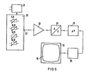
- the individual sensors or strain gauges 5... 13 are shown schematically in a module 20.
- the strain gauges are supplied with voltage by a supply device 21 and can, for example, be connected together in a bridge circuit within the module 20 in such a way that they generate a corresponding electrical signal at the output 22 when a force is exerted on the sensors or strain gauges.
- a measuring amplifier 23 which can also have an integrating effect, these signals are amplified and converted in an A / D converter 24 into a corresponding binary information.
- the microprocessor 25 connected to it converts the signals into corresponding information for the line-type image representation required here and determines, for example, the movement direction and speed variables to be calculated from the vector direction or the vector length of the total force K.
- the output signals of the microprocessor 25 are fed to the signal processing parts of the display device 16 via a display device control 26, so that the effects on the movable cursor 17 or on the change in the image display in the display device 16 can be carried out on the screen 15 with reference to FIGS .
Applications Claiming Priority (2)
| Application Number | Priority Date | Filing Date | Title |
|---|---|---|---|
| DE19843404047 DE3404047A1 (de) | 1984-02-06 | 1984-02-06 | Steuerstab |
| DE3404047 | 1984-02-06 |
Publications (3)
| Publication Number | Publication Date |
|---|---|
| EP0151479A2 true EP0151479A2 (fr) | 1985-08-14 |
| EP0151479A3 EP0151479A3 (en) | 1985-09-18 |
| EP0151479B1 EP0151479B1 (fr) | 1989-05-17 |
Family
ID=6226866
Family Applications (1)
| Application Number | Title | Priority Date | Filing Date |
|---|---|---|---|
| EP85101152A Expired EP0151479B1 (fr) | 1984-02-06 | 1985-02-04 | Dispositif de commande |
Country Status (2)
| Country | Link |
|---|---|
| EP (1) | EP0151479B1 (fr) |
| DE (2) | DE3404047A1 (fr) |
Cited By (18)
| Publication number | Priority date | Publication date | Assignee | Title |
|---|---|---|---|---|
| FR2616956A1 (fr) * | 1987-06-18 | 1988-12-23 | Sintre Francois | Nouveau dispositif pour commandes directionnelles |
| GB2211280A (en) * | 1987-10-16 | 1989-06-28 | Daco Scient Limited | Joystick |
| EP0447334A1 (fr) * | 1990-03-15 | 1991-09-18 | SEXTANT Avionique | Manipulateur à jauges de contrainte |
| WO1993020535A2 (fr) * | 1992-03-25 | 1993-10-14 | Penny & Giles Blackwood Limited | Manette de commande |
| WO1995027890A1 (fr) * | 1994-04-11 | 1995-10-19 | Peter Neltoft | Dispositif de commande manuelle du mouvement d'un objet reel ou imaginaire |
| EP0725329A1 (fr) * | 1995-02-06 | 1996-08-07 | Compaq Computer Corporation | Levier de pointage rétractable pour ordinateur portable |
| WO1996038810A1 (fr) * | 1995-06-02 | 1996-12-05 | Gerhard Wergen | Element analogique de commande |
| EP0864958A3 (fr) * | 1997-03-07 | 1998-09-30 | International Business Machines Corporation | Manette de commande pour dispositifs de traitement d'information |
| WO2000077589A1 (fr) * | 1999-06-11 | 2000-12-21 | Wittenstein Gmbh & Co. Kg | Dispositif de commande d'un appareil |
| EP0844584A3 (fr) * | 1996-11-25 | 2002-07-03 | CTS Corporation | Dispositif de pointage |
| EP1313119A2 (fr) | 2001-11-16 | 2003-05-21 | Robert Bosch Gmbh | Elément de commande |
| DE202004018299U1 (de) * | 2004-11-25 | 2006-04-06 | Liebherr-Hydraulikbagger Gmbh | Baumaschine mit Joystick-Steuerung |
| US20090248042A1 (en) * | 2008-03-27 | 2009-10-01 | Kirschenman Mark B | Model catheter input device |
| US9795447B2 (en) | 2008-03-27 | 2017-10-24 | St. Jude Medical, Atrial Fibrillation Division, Inc. | Robotic catheter device cartridge |
| US9888973B2 (en) | 2010-03-31 | 2018-02-13 | St. Jude Medical, Atrial Fibrillation Division, Inc. | Intuitive user interface control for remote catheter navigation and 3D mapping and visualization systems |
| US10231788B2 (en) | 2008-03-27 | 2019-03-19 | St. Jude Medical, Atrial Fibrillation Division, Inc. | Robotic catheter system |
| US10357322B2 (en) | 2009-07-22 | 2019-07-23 | St. Jude Medical, Atrial Fibrillation Division, Inc. | System and method for controlling a remote medical device guidance system in three-dimensions using gestures |
| US10426557B2 (en) | 2008-03-27 | 2019-10-01 | St. Jude Medical, Atrial Fibrillation Division, Inc. | System and method of automatic detection of obstructions for a robotic catheter system |
Families Citing this family (15)
| Publication number | Priority date | Publication date | Assignee | Title |
|---|---|---|---|---|
| DE3710256A1 (de) * | 1987-03-28 | 1988-10-13 | Wabco Westinghouse Fahrzeug | Sollwertgeber |
| DE3716892A1 (de) * | 1987-05-20 | 1988-12-01 | Fresenius Ag | Vorrichtung zur eingabe von numerischen bzw. alphanumerischen daten in ein geraet |
| DE3830933C1 (fr) * | 1988-09-12 | 1989-10-26 | Eligiusz Dipl.-Ing. 7538 Keltern De Wajda | |
| DE3923890A1 (de) * | 1989-07-19 | 1991-01-31 | Habermeier Peter Dipl Ing Fh | Einrichtung fuer die steuerung eines bildschirm-cursors |
| DE3933575A1 (de) * | 1989-10-07 | 1991-04-18 | Hartmut Prof Dr Janocha | Tasteinrichtung |
| DE19719038C2 (de) * | 1997-04-30 | 2002-10-24 | Art & Com Medientechnologie Un | Vorrichtung und Verfahren und ihre Verwendung zur veränderbaren Darstellung |
| DE19836261C1 (de) * | 1998-08-11 | 1999-12-09 | Mannesmann Vdo Ag | Bedienvorrichtung mit einem Drehschalter |
| DE19837510A1 (de) | 1998-08-19 | 2000-02-24 | Bayerische Motoren Werke Ag | Vorrichtung zur Steuerung der Wiedergabe eines auf einem Fahrzeug-Bildschirm dargestellten Bildes |
| DE19903830A1 (de) * | 1999-02-01 | 2000-08-17 | Asim Genc | Dateneingabe- und/oder Steuergerät, insbesondere für einen Computer |
| US9241768B2 (en) | 2008-03-27 | 2016-01-26 | St. Jude Medical, Atrial Fibrillation Division, Inc. | Intelligent input device controller for a robotic catheter system |
| US8317744B2 (en) | 2008-03-27 | 2012-11-27 | St. Jude Medical, Atrial Fibrillation Division, Inc. | Robotic catheter manipulator assembly |
| WO2009120982A2 (fr) | 2008-03-27 | 2009-10-01 | St. Jude Medical, Atrial Fibrillation Division, Inc. | Système de cathéter robotisé avec réponse dynamique |
| US8641663B2 (en) | 2008-03-27 | 2014-02-04 | St. Jude Medical, Atrial Fibrillation Division, Inc. | Robotic catheter system input device |
| US8754910B2 (en) | 2008-10-01 | 2014-06-17 | Logitech Europe S.A. | Mouse having pan, zoom, and scroll controls |
| US9330497B2 (en) | 2011-08-12 | 2016-05-03 | St. Jude Medical, Atrial Fibrillation Division, Inc. | User interface devices for electrophysiology lab diagnostic and therapeutic equipment |
Citations (5)
| Publication number | Priority date | Publication date | Assignee | Title |
|---|---|---|---|---|
| US3447766A (en) * | 1967-02-14 | 1969-06-03 | Bendix Corp | Control stick with solid state sensors |
| DE2030048A1 (de) * | 1970-06-12 | 1971-11-04 | Askania Gmbh | Steuervorrichtung mit einem nach Art eines Steuerknüppels ausgebildeten verschwenkbaren Hand-Betätigungsglied |
| US3628394A (en) * | 1970-02-09 | 1971-12-21 | Sperry Rand Corp | Operator-manipulative control apparatus |
| FR2312070A1 (fr) * | 1975-05-23 | 1976-12-17 | France Etat | Organe de puissance pour pilotage en effort pur |
| JPS58172739A (ja) * | 1982-04-02 | 1983-10-11 | Toshiba Corp | 三次元ジヨイステイツク装置 |
Family Cites Families (3)
| Publication number | Priority date | Publication date | Assignee | Title |
|---|---|---|---|---|
| US4161726A (en) * | 1977-04-06 | 1979-07-17 | Texas Instruments Incorporated | Digital joystick control |
| US4148014A (en) * | 1977-04-06 | 1979-04-03 | Texas Instruments Incorporated | System with joystick to control velocity vector of a display cursor |
| DE2942003C2 (de) * | 1979-10-17 | 1984-08-02 | Danfoss A/S, Nordborg | Elektrische Steuervorrichtung mit einem Steuerhebel |
-
1984
- 1984-02-06 DE DE19843404047 patent/DE3404047A1/de not_active Withdrawn
-
1985
- 1985-02-04 DE DE8585101152T patent/DE3570301D1/de not_active Expired
- 1985-02-04 EP EP85101152A patent/EP0151479B1/fr not_active Expired
Patent Citations (5)
| Publication number | Priority date | Publication date | Assignee | Title |
|---|---|---|---|---|
| US3447766A (en) * | 1967-02-14 | 1969-06-03 | Bendix Corp | Control stick with solid state sensors |
| US3628394A (en) * | 1970-02-09 | 1971-12-21 | Sperry Rand Corp | Operator-manipulative control apparatus |
| DE2030048A1 (de) * | 1970-06-12 | 1971-11-04 | Askania Gmbh | Steuervorrichtung mit einem nach Art eines Steuerknüppels ausgebildeten verschwenkbaren Hand-Betätigungsglied |
| FR2312070A1 (fr) * | 1975-05-23 | 1976-12-17 | France Etat | Organe de puissance pour pilotage en effort pur |
| JPS58172739A (ja) * | 1982-04-02 | 1983-10-11 | Toshiba Corp | 三次元ジヨイステイツク装置 |
Non-Patent Citations (2)
| Title |
|---|
| IBM TECHNICAL DISCLOSURE BULLETIN, Band 13, Nr. 2, Juli 1970, Seiten 578-579, New York, US; C.J. EVANGELISTI u.a.: "Manipulator" * |
| PATENTS ABSTRACTS OF JAPAN, Band 8, Nr. 14 (P-249)[1451], 21. Januar 1984; & JP-A-58 172 739 (TOKYO SHIBAURA DENKI K.K.) 11.10.1983 * |
Cited By (28)
| Publication number | Priority date | Publication date | Assignee | Title |
|---|---|---|---|---|
| FR2616956A1 (fr) * | 1987-06-18 | 1988-12-23 | Sintre Francois | Nouveau dispositif pour commandes directionnelles |
| GB2211280A (en) * | 1987-10-16 | 1989-06-28 | Daco Scient Limited | Joystick |
| GB2211280B (en) * | 1987-10-16 | 1991-10-30 | Daco Scient Limited | Joystick |
| EP0447334A1 (fr) * | 1990-03-15 | 1991-09-18 | SEXTANT Avionique | Manipulateur à jauges de contrainte |
| FR2659789A1 (fr) * | 1990-03-15 | 1991-09-20 | Sextant Avionique | Manipulateur a jauges de contrainte. |
| US5228348A (en) * | 1990-03-15 | 1993-07-20 | Sextant Avionique | Strain gauge joystick |
| US5831596A (en) * | 1992-03-25 | 1998-11-03 | Penney & Giles Blackwood Limited | Joystick controller using magnetic position sensors and a resilient control arm with sensor used to measure its flex |
| WO1993020535A3 (fr) * | 1992-03-25 | 1993-11-25 | Penny & Giles Blackwood Ltd | Manette de commande |
| WO1993020535A2 (fr) * | 1992-03-25 | 1993-10-14 | Penny & Giles Blackwood Limited | Manette de commande |
| WO1995027890A1 (fr) * | 1994-04-11 | 1995-10-19 | Peter Neltoft | Dispositif de commande manuelle du mouvement d'un objet reel ou imaginaire |
| US5859372A (en) * | 1994-04-11 | 1999-01-12 | Neltoft; Peter | Device for use in manual control of the movement of a real or imaginary object |
| EP0725329A1 (fr) * | 1995-02-06 | 1996-08-07 | Compaq Computer Corporation | Levier de pointage rétractable pour ordinateur portable |
| WO1996038810A1 (fr) * | 1995-06-02 | 1996-12-05 | Gerhard Wergen | Element analogique de commande |
| US6201196B1 (en) | 1995-06-02 | 2001-03-13 | Gerhard Wergen | Joystick assembly |
| EP0844584A3 (fr) * | 1996-11-25 | 2002-07-03 | CTS Corporation | Dispositif de pointage |
| EP0864958A3 (fr) * | 1997-03-07 | 1998-09-30 | International Business Machines Corporation | Manette de commande pour dispositifs de traitement d'information |
| WO2000077589A1 (fr) * | 1999-06-11 | 2000-12-21 | Wittenstein Gmbh & Co. Kg | Dispositif de commande d'un appareil |
| EP1528449A1 (fr) | 1999-06-11 | 2005-05-04 | Wittenstein AG | Dispositif de commande d'un appareil |
| EP1313119A2 (fr) | 2001-11-16 | 2003-05-21 | Robert Bosch Gmbh | Elément de commande |
| EP1313119A3 (fr) * | 2001-11-16 | 2005-05-04 | Robert Bosch Gmbh | Elément de commande |
| DE202004018299U1 (de) * | 2004-11-25 | 2006-04-06 | Liebherr-Hydraulikbagger Gmbh | Baumaschine mit Joystick-Steuerung |
| US20090248042A1 (en) * | 2008-03-27 | 2009-10-01 | Kirschenman Mark B | Model catheter input device |
| US9795447B2 (en) | 2008-03-27 | 2017-10-24 | St. Jude Medical, Atrial Fibrillation Division, Inc. | Robotic catheter device cartridge |
| US10231788B2 (en) | 2008-03-27 | 2019-03-19 | St. Jude Medical, Atrial Fibrillation Division, Inc. | Robotic catheter system |
| US10426557B2 (en) | 2008-03-27 | 2019-10-01 | St. Jude Medical, Atrial Fibrillation Division, Inc. | System and method of automatic detection of obstructions for a robotic catheter system |
| US11717356B2 (en) | 2008-03-27 | 2023-08-08 | St. Jude Medical, Atrial Fibrillation Division, Inc. | System and method of automatic detection of obstructions for a robotic catheter system |
| US10357322B2 (en) | 2009-07-22 | 2019-07-23 | St. Jude Medical, Atrial Fibrillation Division, Inc. | System and method for controlling a remote medical device guidance system in three-dimensions using gestures |
| US9888973B2 (en) | 2010-03-31 | 2018-02-13 | St. Jude Medical, Atrial Fibrillation Division, Inc. | Intuitive user interface control for remote catheter navigation and 3D mapping and visualization systems |
Also Published As
| Publication number | Publication date |
|---|---|
| EP0151479A3 (en) | 1985-09-18 |
| DE3404047A1 (de) | 1985-08-08 |
| DE3570301D1 (en) | 1989-06-22 |
| EP0151479B1 (fr) | 1989-05-17 |
Similar Documents
| Publication | Publication Date | Title |
|---|---|---|
| EP0151479B1 (fr) | Dispositif de commande | |
| DE1940315C3 (de) | Vorrichtung zum Umsetzen der räumlichen Koordinaten der dreidimensionalen Bewegungen eines vorzugsweise handbetätigten mechanischen Steuerorgans in entsprechende elektrische Größen | |
| WO2005058092A1 (fr) | Element mobilier mobile | |
| DE2413997C3 (de) | Bügelmeßschraube | |
| DE7105520U (de) | Vorrichtung zum messen von verschiebungen im zweidimensionalen bereich | |
| DE1698644A1 (de) | Wandler | |
| CH623225A5 (fr) | ||
| DE3902491A1 (de) | Vorrichtung zum feststellen mindestens einer mit der bewegung eines beweglichen koerpers verbundenen variablen | |
| DE8403396U1 (de) | Steuerstab | |
| WO2012034927A1 (fr) | Dispositif optique indicateur de pression activé par ressort | |
| DE1276348B (de) | Messgeber fuer elektrische Spannungen oder Stroeme | |
| DE3246246A1 (de) | Potentiometer | |
| DE102018102991B3 (de) | Bedienelement | |
| DE3512969C2 (fr) | ||
| EP0584652A2 (fr) | Capteur de mesure d'une charge mécanique | |
| DE1002966B (de) | Mehrachs-Dynamometer | |
| DE3909274C2 (fr) | ||
| EP0893391A2 (fr) | Dispositif de commande sans fil | |
| DE3814592A1 (de) | Einrichtung zum feststellen der drehwinkelposition | |
| DE2360965A1 (de) | Elektrischer massen- und kraftmesser | |
| DE202024101392U1 (de) | Schaltbedienelement zur Betätigung durch eine Druckkraft und durch eine Zugkraft für ein Kraftfahrzeug | |
| WO2015067702A1 (fr) | Procédé et dispositif permettant de mesurer la tension d'un tissu dans un métier à tisser | |
| DE3923890C2 (fr) | ||
| DE2512578C3 (de) | Induktive Meßeinrichtung für eine beliebige mechanische Größe | |
| CH409422A (de) | Tastmessvorrichtung zur Bestimmung von Abmessungen an einem Werkstück |
Legal Events
| Date | Code | Title | Description |
|---|---|---|---|
| PUAI | Public reference made under article 153(3) epc to a published international application that has entered the european phase |
Free format text: ORIGINAL CODE: 0009012 |
|
| PUAL | Search report despatched |
Free format text: ORIGINAL CODE: 0009013 |
|
| AK | Designated contracting states |
Designated state(s): DE FR GB |
|
| AK | Designated contracting states |
Designated state(s): DE FR GB |
|
| 17P | Request for examination filed |
Effective date: 19860226 |
|
| 17Q | First examination report despatched |
Effective date: 19880610 |
|
| GRAA | (expected) grant |
Free format text: ORIGINAL CODE: 0009210 |
|
| AK | Designated contracting states |
Kind code of ref document: B1 Designated state(s): DE FR GB |
|
| REF | Corresponds to: |
Ref document number: 3570301 Country of ref document: DE Date of ref document: 19890622 |
|
| GBT | Gb: translation of ep patent filed (gb section 77(6)(a)/1977) | ||
| ET | Fr: translation filed | ||
| PLBE | No opposition filed within time limit |
Free format text: ORIGINAL CODE: 0009261 |
|
| STAA | Information on the status of an ep patent application or granted ep patent |
Free format text: STATUS: NO OPPOSITION FILED WITHIN TIME LIMIT |
|
| 26N | No opposition filed | ||
| PGFP | Annual fee paid to national office [announced via postgrant information from national office to epo] |
Ref country code: FR Payment date: 19910219 Year of fee payment: 7 |
|
| PGFP | Annual fee paid to national office [announced via postgrant information from national office to epo] |
Ref country code: DE Payment date: 19910424 Year of fee payment: 7 |
|
| PGFP | Annual fee paid to national office [announced via postgrant information from national office to epo] |
Ref country code: GB Payment date: 19920117 Year of fee payment: 8 |
|
| PG25 | Lapsed in a contracting state [announced via postgrant information from national office to epo] |
Ref country code: FR Effective date: 19921030 |
|
| PG25 | Lapsed in a contracting state [announced via postgrant information from national office to epo] |
Ref country code: DE Effective date: 19921103 |
|
| REG | Reference to a national code |
Ref country code: FR Ref legal event code: ST |
|
| PG25 | Lapsed in a contracting state [announced via postgrant information from national office to epo] |
Ref country code: GB Effective date: 19930204 |
|
| GBPC | Gb: european patent ceased through non-payment of renewal fee |
Effective date: 19930204 |