EP0151092A2 - Submerged hydraulic piston pump with hydrodynamic transmission - Google Patents
Submerged hydraulic piston pump with hydrodynamic transmission Download PDFInfo
- Publication number
- EP0151092A2 EP0151092A2 EP85830008A EP85830008A EP0151092A2 EP 0151092 A2 EP0151092 A2 EP 0151092A2 EP 85830008 A EP85830008 A EP 85830008A EP 85830008 A EP85830008 A EP 85830008A EP 0151092 A2 EP0151092 A2 EP 0151092A2
- Authority
- EP
- European Patent Office
- Prior art keywords
- piston
- pump
- liquid
- cylinder
- hydraulic pump
- Prior art date
- Legal status (The legal status is an assumption and is not a legal conclusion. Google has not performed a legal analysis and makes no representation as to the accuracy of the status listed.)
- Withdrawn
Links
Images

Classifications
-
- F—MECHANICAL ENGINEERING; LIGHTING; HEATING; WEAPONS; BLASTING
- F04—POSITIVE - DISPLACEMENT MACHINES FOR LIQUIDS; PUMPS FOR LIQUIDS OR ELASTIC FLUIDS
- F04B—POSITIVE-DISPLACEMENT MACHINES FOR LIQUIDS; PUMPS
- F04B47/00—Pumps or pumping installations specially adapted for raising fluids from great depths, e.g. well pumps
- F04B47/06—Pumps or pumping installations specially adapted for raising fluids from great depths, e.g. well pumps having motor-pump units situated at great depth
- F04B47/08—Pumps or pumping installations specially adapted for raising fluids from great depths, e.g. well pumps having motor-pump units situated at great depth the motors being actuated by fluid
Definitions
- the invention relates to a hydraulic submersible piston pump with hydrodhynamic transmission.
- hydraulic piston pumps with reciprocating movement, with single or double effect, with one or more cylinders, with disc or plunger piston, simple or differential, with manual or motor control, currently known provide that the rod the piston is actuated by means of a mechanical transmission which can be of the pendulum type, with crankshaft or oblique disc or rotary seat, etc.
- the range and the height of elevation of these pumps depend on the control force adopted, the dimension and the number of cylinders, the number of cycles per minute, the number of stages, the temperature of the liquid and other factors.
- the suction height is limited by the barometric pressure and by the passive resistances to a maximum of approximately 7-8 m while the range in volume of these pumps is limited to a maximum of around 500-600 l / h.
- the object of the present invention is to increase the elevation height and the range of said hydraulic piston pumps using a low power that of control, such as manual control.
- said pump is distinguished by its high performance, that is to say a height of elevation and a range far greater than those obtained, until now, at the same force as the control, and by the simplicity of its operation.
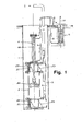
- Figure 1 shows the overall view, in vertical section, of a submerged, double-acting piston pump, produced in accordance with the present invention
- Figure 2 shows the overall view, in vertical section, of a submerged piston pump, single effect, according to the invention.
- the pump shown in Figure 1 of the accompanying drawings comprises: at the bottom of a vertical probe 1, a vertical pump body 2 with piston, which is open at its ends and thus communicates with two manifolds 21 correspondents, which are provided with two stop valves 22-23, respectively of inlet / outlet of the liquid, in phase of pressure / aspiration of the piston 20; a pipe 3 for sending the liquid to the surface, connected to said collectors 21 downstream of the valves 23; machines for the hydrodynamic transmission of the movement to the piston 20 of the pump 2 with a first operating cylinder 4, fixed at the top of the pump 2 and in the axis of the latter, with its own piston 40 operating in tandem with the piston 20 of the pump 2, and with a second surface motor cylinder 5, connected to the first cylinder 4 by two tubes 6 and with liquid in saturation so that, at the down / up stroke of the piston 50 of the cylinder 5 corresponds to the down / up stroke of the piston 40 of the cylinder 4, the diameters of the cylinders 4-5, being differentiated with
- the pump comprises: a vertical probe 1, at the bottom of which is fixed, coaxially, the pump 2, the cylinder of which is open in its lower part and closed in its upper part and whose piston 20 is provided with a valve 22 with valve, making it possible to block the liquid in the pressure phase; a pipe 3 for sending the liquid to the surface, located inside the probe 1, connected to the top of the pump 2 and provided with a retention valve 23 in the aspiration phase; devices for the hydrodynamic transmission of the movement of the piston 20 of the pump 2, similar to those already described for the pump in FIG. 1.
- the pump operates with a single effect. / /
Abstract
Description
L'invention concerne une pompe hydraulique à piston, submergée, à transmission hydrodhynamique.The invention relates to a hydraulic submersible piston pump with hydrodhynamic transmission.
On sait que les pompes hydrauliques à piston, à mou vement alternatif,à effet simple ou double, à un ou plusieurs cylindres, avec piston à disque ou plongeur, simple ou différentiel, avec commande manuelle ou à moteur, actuellement connues prévoient que la tige du piston soit actionnée au moyen d'une transmission mécanique qui peut être de type à balancier, avec arbre à manivelle ou à disque oblique ou à siège rotatif, etc.It is known that hydraulic piston pumps, with reciprocating movement, with single or double effect, with one or more cylinders, with disc or plunger piston, simple or differential, with manual or motor control, currently known provide that the rod the piston is actuated by means of a mechanical transmission which can be of the pendulum type, with crankshaft or oblique disc or rotary seat, etc.
En conséquence, la portée et la hauteur d'élévation de ces pompes de type connu dépendent de la force de commande adoptée, de la dimension et du nombre de cylindres, du nombre de cycles par minute, du nombre de stades, de la température du liquide et d'autres facteurs. D'autre part, on sait également que, pour les pompes à piston à commande manuelle, la hauteur d'aspiration est délimitée par la pression barométrique et par les résistances passives à un maximun d'environ 7-8 m tandis que la portée en volume de ces pompes est limitée à un maximum d' en viron 500-600 1/h.Consequently, the range and the height of elevation of these pumps of known type depend on the control force adopted, the dimension and the number of cylinders, the number of cycles per minute, the number of stages, the temperature of the liquid and other factors. On the other hand, it is also known that, for manually operated piston pumps, the suction height is limited by the barometric pressure and by the passive resistances to a maximum of approximately 7-8 m while the range in volume of these pumps is limited to a maximum of around 500-600 l / h.
Le but de la présente invention est d'accroitre la hauteur d'élévation et la portée desdites pompes hy drauliques à piston en utilisant une faible puissan ce de commande, telle la commande manuelle.The object of the present invention is to increase the elevation height and the range of said hydraulic piston pumps using a low power that of control, such as manual control.
On est parvenu à ce résultat conformément à l'inven tion en adoptant l'idée consistant à appliquer à une pompe à piston submergée une transmission hydro dynamique en circuit fermé.This was achieved in accordance with the invention by adopting the idea of applying to a submerged piston pump a hydro dynamic transmission in a closed circuit.
L'invention, telle qu'elle est caractérisée dans les revendications énoncées ci-dessous, permet d'ob tenir les résultats suivants: l' aspiration d'eau ou d'autres liquides se trouvant meme à grande profondeur (jusqu'à 100 m et au-delà), avec une portée élevée (jusqu'à 5000 1/h) et une force de commande très réduite (≤ 2HP)The invention, as characterized in the claims set out below, allows the following results to be obtained: the suction of water or other liquids even at great depths (up to 100 m and beyond), with a high range (up to 5000 1 / h) and a very reduced control force (≤ 2HP)
Les avantages obtenus grace à la présente invention consistent essentiellement en ce que toutes les com posantes de la pompe peuvent etre trouvées dans la commerce; en ce que sa construction est simple, rapide et économique; en ce qu'il est possible de l' installer avec les méthodes ordinaires et tradition nelles utilisées pour les forages; en ce que le cout d'exercice est fort réduit; en ce qu'elle peut etre manoeuvrée facilement meme par du personnel non qualifié; en ce qu'elle reste très fiable meme après de longues périodes de fonctionnement.The advantages obtained thanks to the present invention consist essentially in that all the components of the pump can be found commercially; in that its construction is simple, rapid and economical; in that it is possible to install it with the ordinary and traditional methods used for drilling; in that the cost of exercise is greatly reduced; in that it can be easily operated even by unqualified personnel; in that it remains very reliable even after long periods of operation.
Dans l'ensemble, ladite pompe se distingue par ses prestations élevées, c'est-à-dire une hauteur d'élé vation et une portée de loin supérieures à celles obtenues, jusqu'à présent, à parité de force de com mande, et par la simplicité de son fonctionnement.On the whole, said pump is distinguished by its high performance, that is to say a height of elevation and a range far greater than those obtained, until now, at the same force as the control, and by the simplicity of its operation.
L'invention est décrite plus en détails dans les pa ges qui suivant et à l'aide des dessins qui en représentent deux cas d'application.The invention is described in more detail in the pa ges qui après and using the drawings which represent two cases of application.
La Figure 1 représente la vue d'ensemble,en section verticale, d'une pompe à piston submergée, à double effet, réalisée conformément à la présente invention; la Figure 2 représente la vue d'ensemble, en section verticale, d'une pompe à piston submergée, à effet simple, conforme à l'invention.Figure 1 shows the overall view, in vertical section, of a submerged, double-acting piston pump, produced in accordance with the present invention; Figure 2 shows the overall view, in vertical section, of a submerged piston pump, single effect, according to the invention.
Conformément à l'invention, la pompe représentée dans la figure 1 des dessins ci-joints comprend: au fond d'une sonde 1 verticale, un corps de pompe verticale 2 à piston, qui est ouvert à ses extrémités et communique ainsi avec deux collecteurs 21 correspondants, lesquels sont munis de deux soupapes d'arret 22-23, respectivement d'entrée/sortie du liquide, en phase de pression/aspiration du piston 20; un tuyau 3 pour l'envoi du liquide à la surface, relié auxdits collecteurs 21 en aval des soupapes 23; des engins pour la transmission hydrodynamique du mouvement au piston 20 de la pompe 2 avec un premier cylindre 4 opérateur,fixé au sommet de la pompe 2 et dans l'axe de celle-ci, avec son propre piston 40 fonctionnant en tandem avec le piston 20 de la pompe 2, et avec un second cylindre 5 moteur, de surface, relié au premier cylindre 4 par deux tubes 6 et avec du liquide en saturation de sorte que, à la course descendante/ascendante du piston 50 du cylindre 5 corresponde la course descendante/ascendante du piston 40 du cylindre 4, les diamétres des cylindres 4-5, étant différentiés l'un par rapport à l'autre (avec celui du cylindre 5,supérieur à celui du cylindre 4) et par rapport à celui de la pompe 2 (ce dernier étant supérieur aux deux autres); une roue motrice (par souci de simpli fication, celle-ci n'est pas représentée sur les dessins) permettant d'actionner la tige 51 du cylin dre 5 par commande manuelle ou à moteur, pour activer le circuit de transmission hydrodynamique et ainsi faire agir la pompe avec fonctionnement à double effet.According to the invention, the pump shown in Figure 1 of the accompanying drawings comprises: at the bottom of a
En se référant à la Figure 2 des.dessins ci-joints, la pompe conforme à l'invention comprend: une sonde 1 verticale, au fond de laquelle est fixée, de ma- niére coaxiale, la pompe 2 dont le cylindre est ouvert dans sa partie inférieure et fermé dans sa par tie supérieure et dont le piston 20 est muni d'une soupape 22 à clapet, permettant de bloquer le liqui de dans la phase de pression; un tuyau 3 permettant d'envoyer le liquide à la surface, situé à l'intérieur de la sonde 1, relié au sommet de la pompe 2 et muni d'une soupape 23 de rétention en phase d'as piration; des engins pour la transmission hydrodyna mique du mouvement du piston 20 de la pompe 2, semblables à ceux déjà décrits pour la pompe de la figure 1. Dans ce cas, la pompe fonctionne à effet simple. / /Referring to Figure 2 of the attached drawings, the pump according to the invention comprises: a
Claims (6)
Applications Claiming Priority (2)
| Application Number | Priority Date | Filing Date | Title |
|---|---|---|---|
| IT1830284 | 1984-01-18 | ||
| IT18302/84A IT1221133B (en) | 1984-01-18 | 1984-01-18 | HYDRAULIC PUMP WITH DIRECT TAKE AND HYPRODYNAMIC TRANSMISSION |
Publications (2)
| Publication Number | Publication Date |
|---|---|
| EP0151092A2 true EP0151092A2 (en) | 1985-08-07 |
| EP0151092A3 EP0151092A3 (en) | 1985-08-28 |
Family
ID=11152543
Family Applications (1)
| Application Number | Title | Priority Date | Filing Date |
|---|---|---|---|
| EP85830008A Withdrawn EP0151092A3 (en) | 1984-01-18 | 1985-01-16 | Submerged hydraulic piston pump with hydrodynamic transmission |
Country Status (2)
| Country | Link |
|---|---|
| EP (1) | EP0151092A3 (en) |
| IT (1) | IT1221133B (en) |
Cited By (5)
| Publication number | Priority date | Publication date | Assignee | Title |
|---|---|---|---|---|
| FR2630785A1 (en) * | 1988-05-02 | 1989-11-03 | Inst Francais Du Petrole | POLYPHASTIC PISTON PUMPING DEVICE AND APPLICATIONS THEREOF |
| EP0398977A1 (en) * | 1988-01-26 | 1990-11-28 | Milam/Clardy, Inc. | Apparatus for removing fluid from the ground and method for same |
| DE19533046A1 (en) * | 1995-09-07 | 1997-03-13 | Preussag En Gmbh | Underground pump transmission, esp. for use in oil industry |
| FR2764345A1 (en) * | 1997-06-09 | 1998-12-11 | Inst Francais Du Petrole | Pump for extracting fluids at low pressure from bottom of shaft |
| ES2329537A1 (en) * | 2007-06-19 | 2009-11-26 | Guillermo Perez Celada | Pumping device (Machine-translation by Google Translate, not legally binding) |
Citations (3)
| Publication number | Priority date | Publication date | Assignee | Title |
|---|---|---|---|---|
| US1630902A (en) * | 1924-04-16 | 1927-05-31 | William C Parrish | Pumping system |
| GB601616A (en) * | 1945-07-23 | 1948-05-10 | Richard Harland Dickinson | Improvements in or relating to reciprocating pumps |
| FR1261829A (en) * | 1960-07-07 | 1961-05-19 | Improvements concerning liquid pumping installations comprising piston pumps |
-
1984
- 1984-01-18 IT IT18302/84A patent/IT1221133B/en active
-
1985
- 1985-01-16 EP EP85830008A patent/EP0151092A3/en not_active Withdrawn
Patent Citations (3)
| Publication number | Priority date | Publication date | Assignee | Title |
|---|---|---|---|---|
| US1630902A (en) * | 1924-04-16 | 1927-05-31 | William C Parrish | Pumping system |
| GB601616A (en) * | 1945-07-23 | 1948-05-10 | Richard Harland Dickinson | Improvements in or relating to reciprocating pumps |
| FR1261829A (en) * | 1960-07-07 | 1961-05-19 | Improvements concerning liquid pumping installations comprising piston pumps |
Cited By (10)
| Publication number | Priority date | Publication date | Assignee | Title |
|---|---|---|---|---|
| EP0398977A1 (en) * | 1988-01-26 | 1990-11-28 | Milam/Clardy, Inc. | Apparatus for removing fluid from the ground and method for same |
| EP0398977A4 (en) * | 1988-01-26 | 1992-08-19 | Milam/Clardy, Inc. | Apparatus for removing fluid from the ground and method for same |
| FR2630785A1 (en) * | 1988-05-02 | 1989-11-03 | Inst Francais Du Petrole | POLYPHASTIC PISTON PUMPING DEVICE AND APPLICATIONS THEREOF |
| WO1989011038A2 (en) * | 1988-05-02 | 1989-11-16 | Institut Français Du Petrole | Piston pump for multiphase fluids and applications thereof |
| WO1989011038A3 (en) * | 1988-05-02 | 1989-12-14 | Inst Francais Du Petrole | Piston pump for multiphase fluids and applications thereof |
| DE19533046A1 (en) * | 1995-09-07 | 1997-03-13 | Preussag En Gmbh | Underground pump transmission, esp. for use in oil industry |
| DE19533046C2 (en) * | 1995-09-07 | 1999-05-06 | Preussag En Gmbh | Underground deep pump drive |
| FR2764345A1 (en) * | 1997-06-09 | 1998-12-11 | Inst Francais Du Petrole | Pump for extracting fluids at low pressure from bottom of shaft |
| US6203289B1 (en) | 1997-06-09 | 2001-03-20 | Institut Francais Du Petrole | Hydraulic alternating volumetric pumping system |
| ES2329537A1 (en) * | 2007-06-19 | 2009-11-26 | Guillermo Perez Celada | Pumping device (Machine-translation by Google Translate, not legally binding) |
Also Published As
| Publication number | Publication date |
|---|---|
| IT8418302A0 (en) | 1984-01-18 |
| IT1221133B (en) | 1990-06-21 |
| EP0151092A3 (en) | 1985-08-28 |
Similar Documents
| Publication | Publication Date | Title |
|---|---|---|
| FR2465103A1 (en) | FLUID PUMP | |
| EP0151092A2 (en) | Submerged hydraulic piston pump with hydrodynamic transmission | |
| FR2802250A3 (en) | Hydraulic power converter consists of main oil tank, hydraulic pumps, motor, and two-circuit hydraulic cylinder mechanism | |
| FR2532876A1 (en) | Percussion machine | |
| FR2482190A1 (en) | POWER AMPLIFIER FOR HEAT ENGINES OR OTHER | |
| FR2647508A1 (en) | Internal combustion engine with a variable compression ratio | |
| FR2783514A3 (en) | Rapid acting hydraulic unit, for use in jack, has three concentric cylindrical oil chambers, with innermost chamber containing drift, fixed to base to allow oil through to operate main stem | |
| FR2805313A1 (en) | PNEUMATICALLY DRIVEN HYDRAULIC PUMP | |
| EP0180510B1 (en) | Hydraulic piston pump with positively driven inlet valves | |
| FR1464906A (en) | Star piston cylinder type pump | |
| FR2607537A1 (en) | Composite device for dispensing a concrete or a coating | |
| FR2557927A1 (en) | Hydraulic motor with reciprocating jack which can be used in particular for pumping crude oil | |
| BE445498A (en) | ||
| FR2561062A1 (en) | Tree stump removing machine | |
| CH104636A (en) | Rotary piston pump. | |
| CH150068A (en) | Hydraulic energy transmission device. | |
| CH156843A (en) | Liquid pump. | |
| FR2585413A1 (en) | Manual emergency pump with variable flow rate | |
| BE536487A (en) | ||
| FR2637945A1 (en) | HYDRAULIC APPARATUS HAVING AN ORIFICE ROTATING PLATE | |
| OA10004A (en) | Pump - especially for liquid - drilling and deep wells of small and large diameters | |
| BE491379A (en) | ||
| BE390996A (en) | ||
| CH509096A (en) | Seawater distillation plant | |
| FR2677420A1 (en) | Device of the motor or pump type with orthogonal axes |
Legal Events
| Date | Code | Title | Description |
|---|---|---|---|
| PUAI | Public reference made under article 153(3) epc to a published international application that has entered the european phase |
Free format text: ORIGINAL CODE: 0009012 |
|
| PUAL | Search report despatched |
Free format text: ORIGINAL CODE: 0009013 |
|
| AK | Designated contracting states |
Kind code of ref document: A2 Designated state(s): AT BE CH DE FR GB LI LU NL SE Designated state(s): AT BE CH DE FR GB LI LU NL SE |
|
| AK | Designated contracting states |
Kind code of ref document: A3 Designated state(s): AT BE CH DE FR GB LI LU NL SE Designated state(s): AT BE CH DE FR GB LI LU NL SE |
|
| STAA | Information on the status of an ep patent application or granted ep patent |
Free format text: STATUS: THE APPLICATION IS DEEMED TO BE WITHDRAWN |
|
| 18D | Application deemed to be withdrawn |
Effective date: 19860429 |
|
| RIN1 | Information on inventor provided before grant (corrected) |
Inventor name: VITA, ROBERTO |